📝 Key Takeaways:
Mastering Two-Stage Programming for Webs
Pr…
[VIDEO_HERE]
Preface: Why Two-Stage Programming?
Hello everyone, I’m Master Wang. I’ve been in the machining industry for fifteen years, and I’ve seen it all—turning, milling, planing, grinding, EDM. Siemens NX programming is second nature to me. Today, we’re not going to talk theory; instead, we’ll dive into the web machining of this part and discuss how to master two-stage programming, especially those real-world tricks you won’t learn from textbooks. We’ve already finished machining Side A of the part, so now, let’s flip it over and tackle Side B. Listen closely, because these are genuine, hard-earned insights!
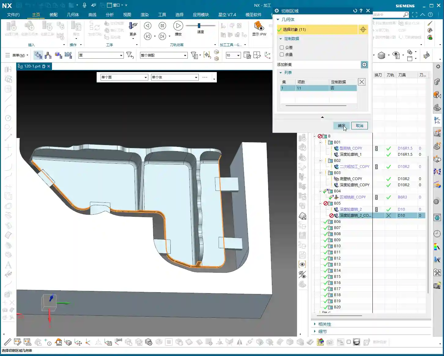
Side B Work Coordinate System and Stock Definition: Getting Started Right
First, you need to create the Work Coordinate System for Side B. Select your B-axis for the setup, then specify a plane, for example, by inputting a distance of 100mm, and establish its position. This is the absolute basics; if your Work Coordinate System isn’t set up correctly, your tool will get “lost,” and every path will be wrong.
Next up is the stock. While I often say that programs can be copied and pasted for convenience and speed, you absolutely must re-verify the stock selection after copying. Especially in multi-sided machining, the stock geometry varies in different orientations. If the stock is selected incorrectly, the program might still generate, but the resulting part will be vastly different from what you intended—a complete waste of effort!
Roughing Strategy: Digging into Details, Avoiding Pitfalls
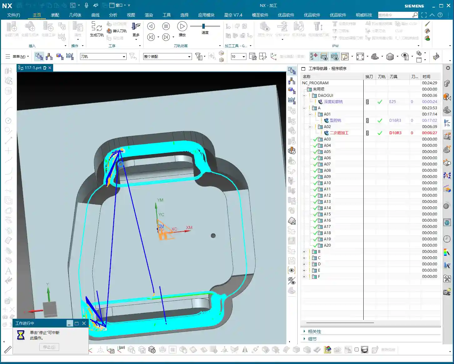
Two-Stage Roughing: The Wisdom of Layered Progression
For structures like webs that require significant material removal, we typically adopt a two-stage roughing strategy: “first roughing pass” and “second roughing pass.” Simply put, first use a large tool with a significant Depth of Cut (DOC) to remove most of the material (first roughing pass), then switch to a smaller tool, or reduce the Depth of Cut, to more carefully remove the remaining material (second roughing pass), preparing for the subsequent Finishing pass.
As I always say, “For roughing, first rough it down to the bottom, then follow up with a second roughing pass.” The goal is clear: ensure efficiency while effectively controlling tool wear and preventing excessive cutting loads in a single pass that could lead to chipped or broken tools.

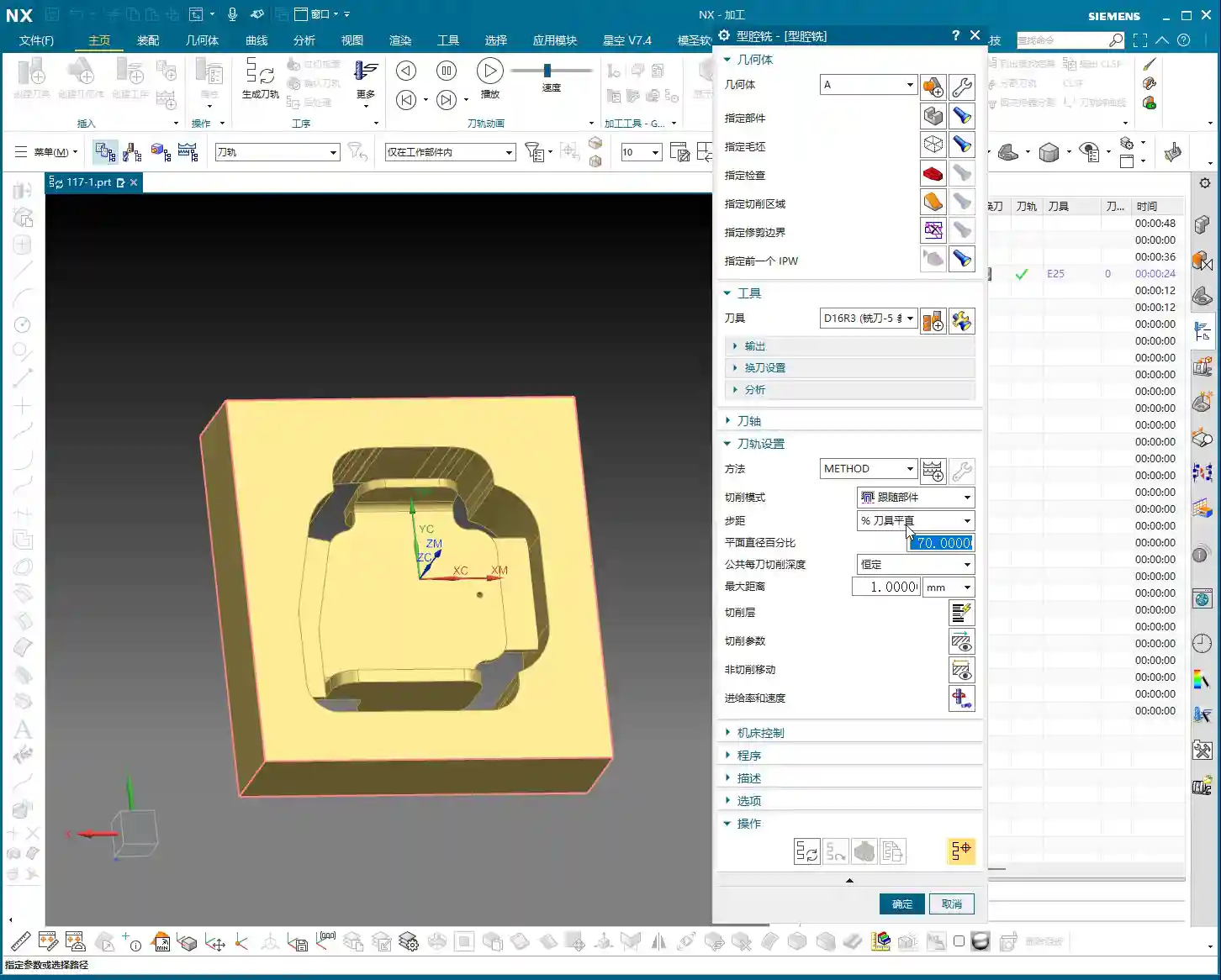
Stock Allowance Control and Toolpath Depth: Striving for Perfection
During roughing, many people like to mill a bit deeper, perhaps an extra 1.5mm or 2.2mm, thinking it’s safer. This is a good habit for ensuring complete material removal. However, there’s a “pitfall” you need to watch out for:
- Master Wang Reveals:“Milling excessively deep is often pointless, because the tool is too large.” Understand? You can set any depth in the software, but in reality, if your tool size is relatively large, or if the part’s geometry is restrictive, the tool simply cannot reach that depth. The extra depth you set won’t be cut, just wasting calculation time. So, don’t just rely on software simulation; look at the cutting sparks!
- Core Principle: For the first roughing pass, you only need to ensure efficient removal of the bulk material; don’t overthink that extra bit of milling depth. The precise depth control is truly needed during the second roughing pass. At this stage, we’ll consider going “an extra 2.2mm or so,” because the tool is relatively smaller and can reach the desired depth more effectively.
- Master Wang’s Reminder: Especially in complex structures like webs, which are prone to dead ends, “this area is prone to heavy cutting loads,” so toolpaths must be carefully controlled to avoid overload.
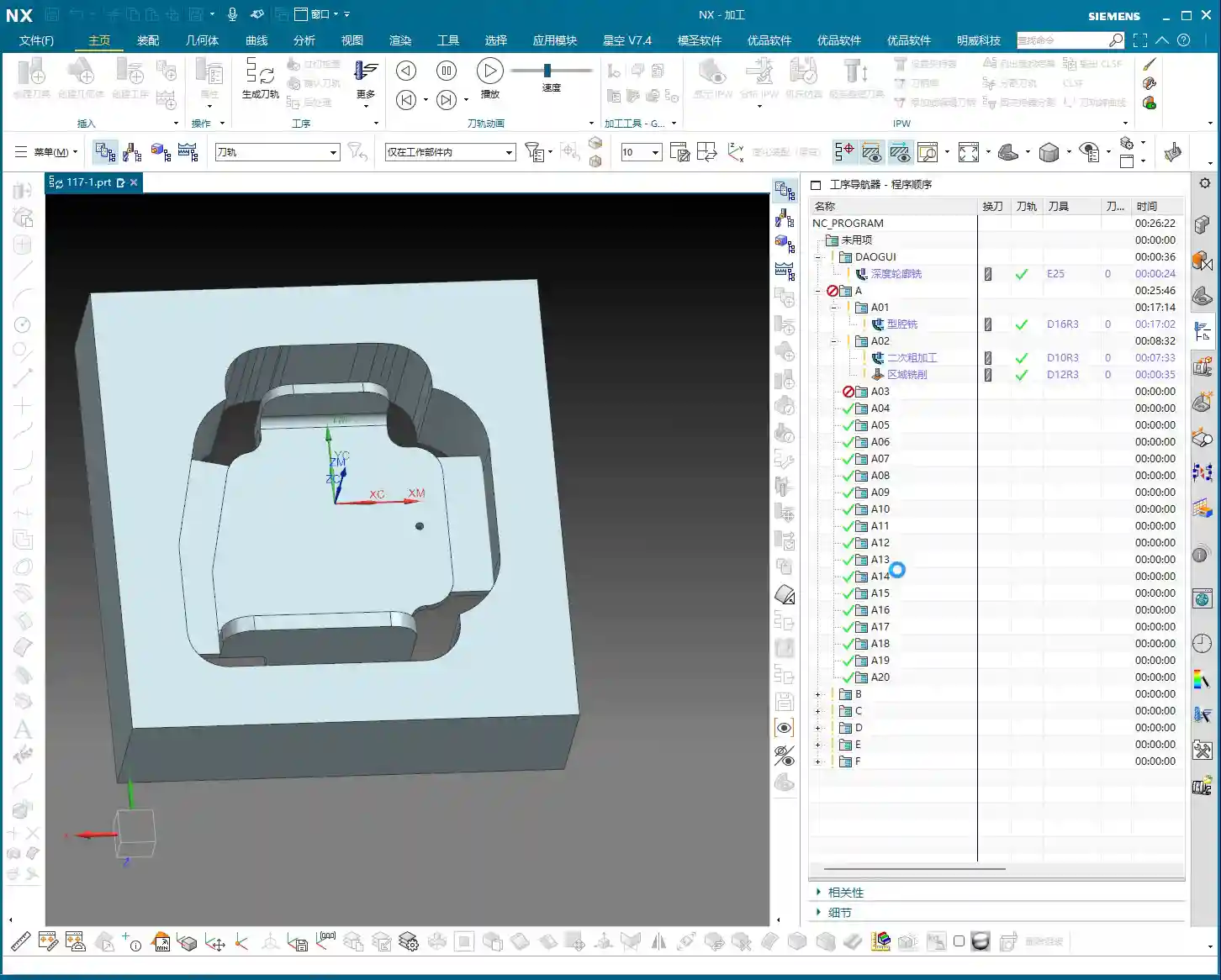
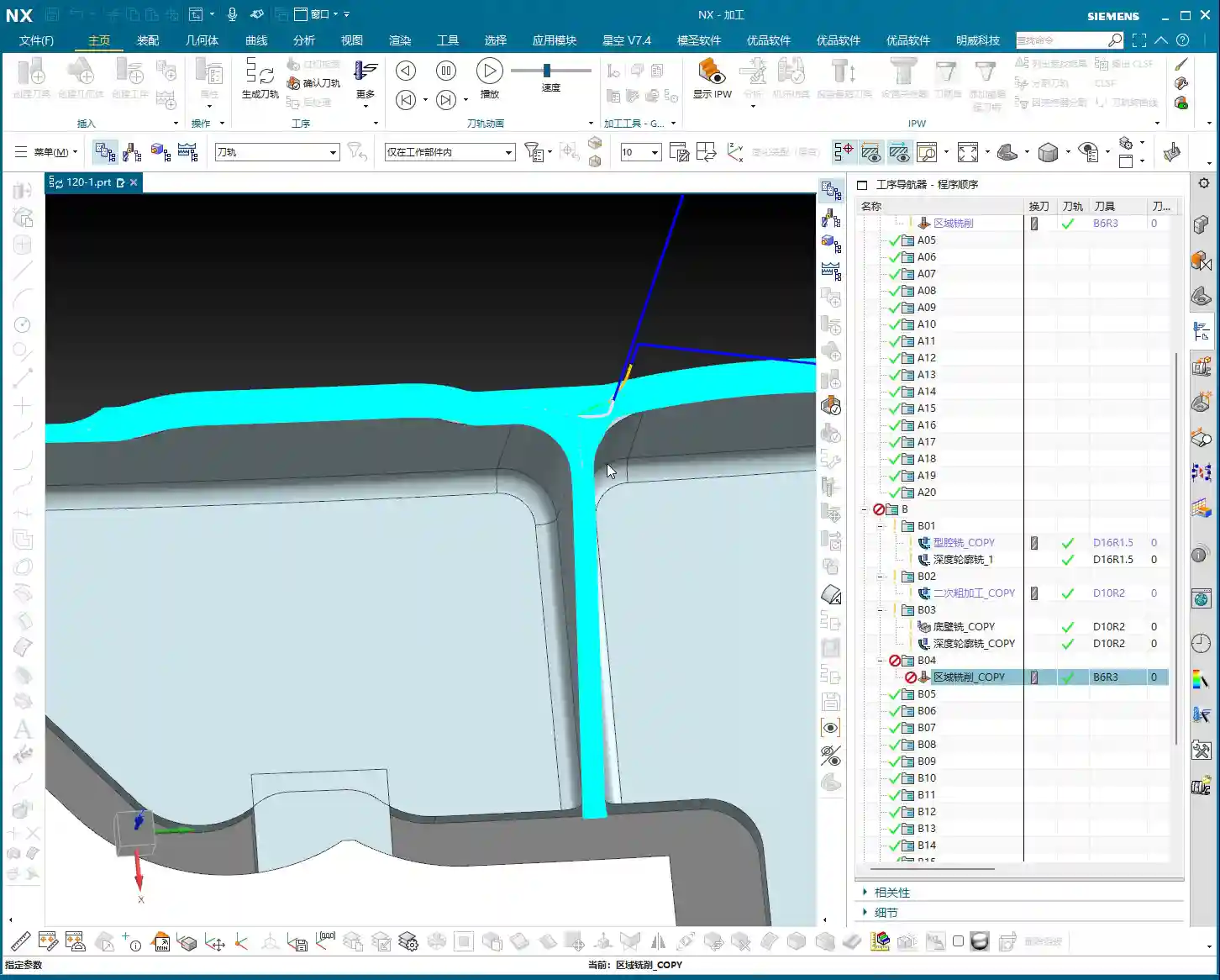
Residual Stock Removal: Leaving No Dead Ends
After roughing, there are always some areas where, due to tool size limitations or complex geometry, some “internal residual stock” remains (audio 3:26). If these remnants aren’t thoroughly cleaned up, they’ll cause problems for the subsequent Finishing pass.
For this residual stock, we typically use specialized toolpath strategies, such as “Deep Profile Milling” or “Hybrid Milling,” using smaller tools for Corner Cleanup or Rest Milling.
Master Wang’s Experience: This is a crucial detail: “It’s best not to set it to zero stock; if you do, toolpaths will also appear on the exterior.” What does this mean? It means that at the edges of the roughing pass, do not set the stock allowance to 0mm. Even leaving a 0.05mm stock allowance can significantly reduce the risk of the tool scratching the workpiece edges, preventing burrs. This is a practical trick you won’t learn from textbooks, and it can save you a lot of rework time and money!
Of course, for external contours that do not connect to subsequent finishing surfaces, you can choose to leave no stock allowance and mill directly to size; that’s perfectly fine.

Finishing Process: The Secrets of Surface Finish
Tool Selection and Feed Strategy: Pursuing Perfection
Finishing pass, as the name suggests, aims for optimal surface finish and dimensional accuracy. Therefore, we typically select tools with smaller radii, such as the R1.5 or R2 ball nose or bull nose end mills that I frequently use.
For toolpath strategy, the Finishing pass often opts to “feed in from the outside, milling inwards for the finish cut.” This avoids the impact and tool marks that can occur when a tool directly plunges into the interior of the workpiece, ensuring consistent surface quality.
Master Wang’s Tip: During the Finishing pass, the stock allowance for most curved surfaces or side walls will be set to 0mm to ensure final dimensions. However, for transition areas connecting the bottom and side walls, a small amount of stock allowance (e.g., 0.1mm) is sometimes left for better blending and to avoid overcutting, then smoothed out with strategies like “Hybrid Milling.”
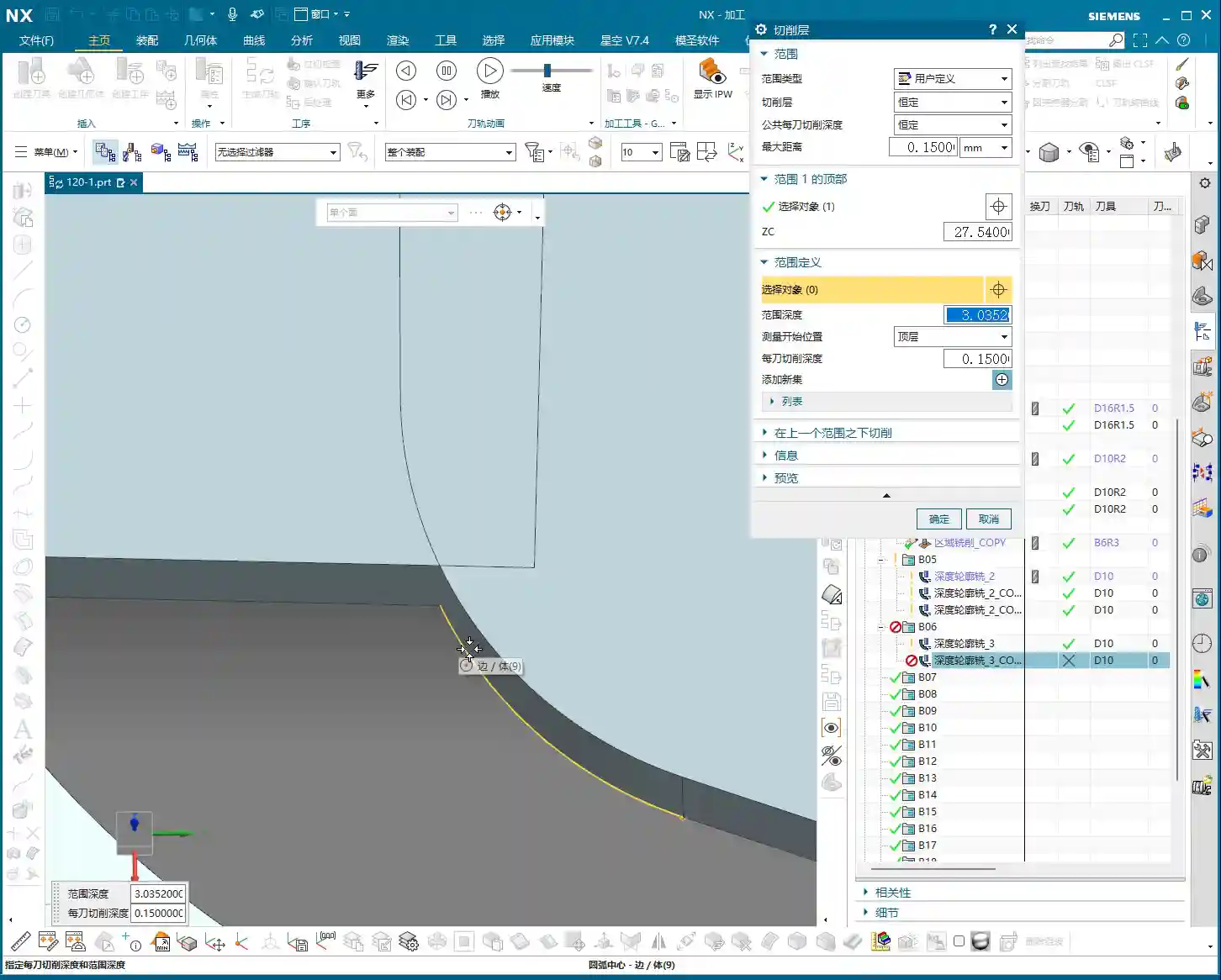
Avoiding Finishing Pitfalls: The Double Toolpath Issue
When programming Finishing passes, you might sometimes notice “two layers of toolpaths” in the software simulation (audio 9:28), even though you only intended for one. This is a common “illusion” and “pitfall” that many people encounter.
Master Wang’s Analysis: Double toolpaths usually occur due to improper datum height or thickness parameter settings. The software interprets a certain height as a datum, then generates an additional layer based on your parameters. This is extremely dangerous in actual machining and can lead to overcutting, air cutting, or even scrapping the part directly!
Solution: When this happens, we must immediately check and adjust the thickness parameter. For example, change the thickness from its default value to a smaller number, such as 0.1mm. As long as this thickness setting is reasonable and distinct from the actual part height, the extra toolpaths will immediately disappear, leaving only the single layer you intended.
Master Wang Emphasizes: “If their heights are different, just reduce it a bit”—this principle applies to many similar scenarios. The core idea is to tell the software what your true machining depth or boundary is.

Program Reuse and Optimization: Efficiency Above All
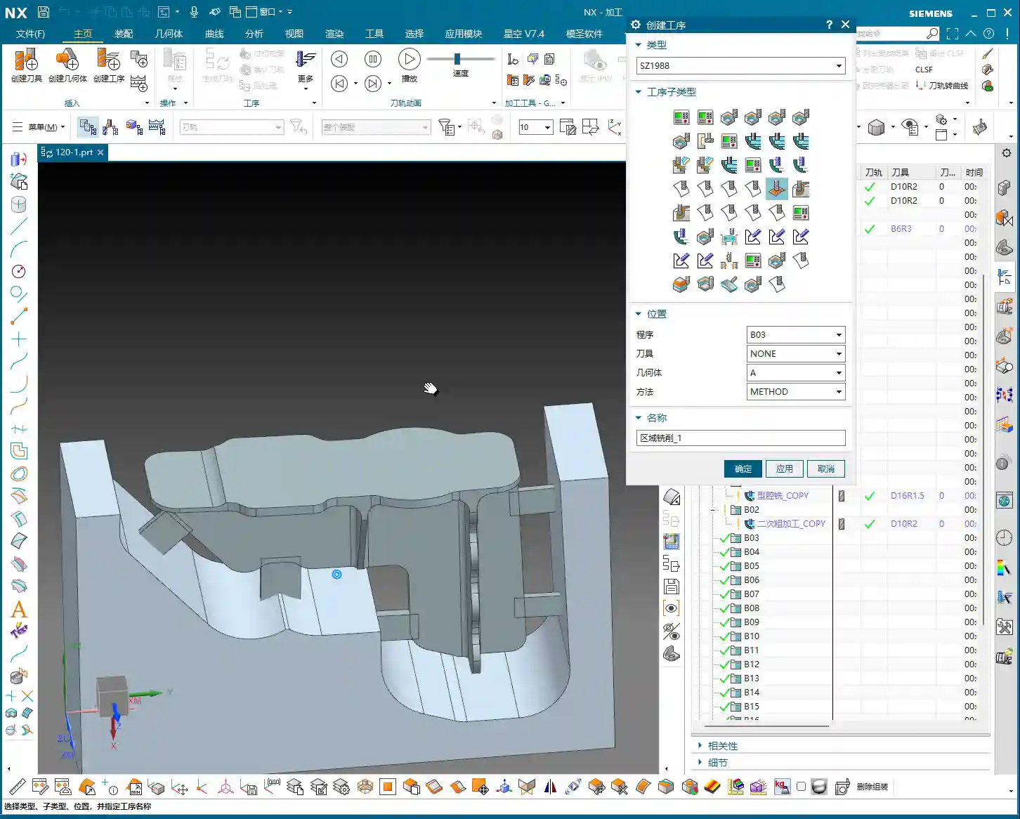
Copying and Modifying: The Siemens NX Programming Shortcut
In practical work, if a part has many similar features, or like our example today, a single part has multiple machining faces, copying existing programs is the most direct way to boost programming efficiency.
Master Wang’s Experience: Copying and pasting is great, but never get lazy. After each copy, you must carefully inspect and modify several core parameters:
- Stock Definition: Ensure it corresponds to the current machining state.
- Machining Face Selection: Re-select the correct machining area.
- Toolpath Depth and Stock Allowance: Adjust according to the roughing and finishing stages and specific requirements.
- Boundary Type: For example, whether to feed in from the outside or inside, and if extension is needed.
Master Wang’s Maxim: “If programs are highly similar, feel free to copy them, but the devil is in the details!” Oversights in minor details are often what lead to rework or even scrapped parts.
Considerations for Machining Sequence: Rough First, Then Finish; Bottom First, Then Sides
A logical machining sequence can significantly improve efficiency and quality. The fundamental principle is to rough first, then finish. However, within the Finishing pass itself, there’s another subtle point.
Master Wang Suggests: “You should finish the bottom first, then the side walls.” Why? Because machining the bottom first ensures its flatness, providing a stable datum for the subsequent Finishing pass of the side walls. If you machine the side walls first and then the bottom, vibrations or chips generated during the bottom cutting might scratch the already finished side walls, affecting the surface finish. These are all lessons learned the hard way!

Master Wang’s SEO and Promotion Secrets
In this digital age, simply being able to craft high-precision parts by hand isn’t enough. You also need to ensure your products, your technology, can be seen by customers amidst the vast network. If you can both manually machine high-precision parts and ensure your product keywords consistently rank on the first page of search engines, that’s true skill!
So, Master Wang is not just a veteran on the shop floor, but also an expert in online promotion. When writing these technical tutorials, I deliberately integrate common industry technical terms and pain points, such as “Siemens NX programming,” “web machining,” “stock allowance control,” “machining pitfalls,” and so on. This is what we call SEO (Search Engine Optimization).
Remember, no matter how good your technology is, it’s useless if no one knows about it. Learning to disseminate your professional knowledge in a way customers can understand and find is as important as achieving a machining accuracy of ±0.005mm on the machine!
Summary: A Pitfall Guide
Finally, Master Wang has summarized a few points for you; these are common mistakes in real-world machining. Avoid them, and you’ll save yourself a lot of trouble:
- Don’t blindly trust software simulations: It’s just a tool; the final result depends on the actual tool, material, and machine conditions.
- Leave stock allowance on roughing boundaries: Even 0.05mm can effectively prevent the tool from scratching the workpiece edges and avoid burrs.
- Beware of double toolpaths during finishing: Carefully check height and thickness parameters, adjusting as necessary to ensure only one effective toolpath.
- Plan your machining sequence logically: Especially for Finishing passes, “bottom first, then sides” can improve quality and efficiency.
- Be meticulous with program reuse: After copying and pasting, key parameters such as stock, machining faces, depth, stock allowance, and boundaries must be checked one by one.
- Avoid frequent tool changes: Unless strictly required by the process, try to complete similar operations with the same tool to reduce tool change time.
- Setting “zero stock” is a pitfall; avoid it unless absolutely necessary: Especially in edges and transition areas, it’s better to leave a tiny bit of stock allowance than to overcut or scratch the part.
Alright, that concludes today’s lesson. Go back, reflect on it, get hands-on, and ask me if you have any questions!
👤 About the Author:
The author is a veteran CNC machining professional with 15 years of industry experience, specializing in UG NX programming. This article is an original work representing personal practical insights.
⚠️ Copyright Notice: Unauthorized reproduction or distribution without prior communication is strictly prohibited.