📝 Key Takeaways:
Siemens NX Connecting Rod Programming Case Study: From Raw Stock to Finish Machining
Master Wang Speaks: First Steps in Siemens NX Connecting Rod Programming
Alright, listen up, everyone, it’s Master Wang here. Today, we’re not getting bogged down in abstract theories. We’re getting straight to it, programming this connecting rod part right here in NX. I’ve been at this for fifteen years, and I know exactly where the tool engagement issues lie and where you can cut corners to boost efficiency – it’s crystal clear to me. Today, I’ll walk you through the machining program for this part, step-by-step, from raw stock to finish machining – every single step will be practical and precise.
Work Coordinate System (WCS) Setup: Don’t Overlook These Details
First off, let’s talk about the Work Coordinate System (WCS). That’s what we usually call the part coordinate system. In NX, it might seem like it doesn’t matter where you place it, but for us, the goal is convenience and clarity. Initially, the WCS might default to being elevated by 1 mm. While it might not significantly affect the machining outcome, do you honestly feel comfortable seeing it hanging 1 mm in mid-air?
We need to level it. Just double-click the WCS, input ‘-1’ in the Z-axis direction, confirm, and it’ll sit snugly on the part’s highest face. This makes it visually comfortable, and subsequent programming becomes more intuitive. It’s about ‘seeing is believing,’ understand? Don’t just rely on software simulations; it’s crucial to have a clear mental picture.

Tool Selection: Roughing and Finishing with Strategy, Efficiency First
Tool selection is a critical skill; it directly impacts your machining efficiency and part quality. This connecting rod part has flats, sidewalls, and curved surfaces, with gaps roughly around 12.5 mm.
* **Roughing**: The goal of this first pass is to remove the bulk of the material. Since the gaps aren’t small, we definitely need a larger tool. For example, a ∅16 R3 bull nose end mill, or a ∅12 R3 tool would both work. Remember, roughing is all about aggression and maximizing efficiency.
* **Finishing Sidewalls**: Finishing the sidewalls requires balancing accuracy and surface finish. We can choose a ∅4 R3 bull nose end mill; this size allows for corner cleanup of small radii while maintaining stable cutting along the sidewalls.
* **Finishing Curved Surfaces**: This part has curved surfaces, so for surface milling, we’ll need to use a ball end mill. Considering the part isn’t exceptionally large, a ∅8 R4 or ∅6 R4 ball end mill should suffice. A smaller tool will produce a better surface finish on the curves, but efficiency will decrease, so you need to find a balance. If you go straight for a larger ball end mill, the curved surface definitely won’t be as smooth – that’s just experience talking.

Roughing Strategy: Steady, Accurate, Aggressive!
Let’s start with the roughing program.
1. **Stock Definition**: In NX, the blank or stock often defaults to being invisible or inaccurate. So, the first step is to insert a Geometry and select Workpiece for roughing. Then, select the entire part and set the Z-direction stock to zero. As a personal habit, I usually place the raw stock on Layer 100; it makes management easier. Once the stock is defined, remember to hide it; otherwise, it gets in the way visually.
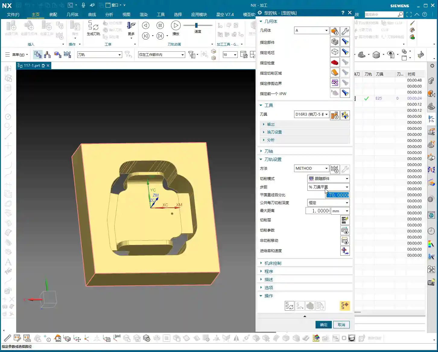
2. **Create Operation**: Right-click to insert an operation, and select Cavity Mill.
3. **Specify Part**: Select our entire connecting rod part.
4. **Select Tool**: We’ll use the ∅16 R3 tool we discussed earlier; it’s a large tool and removes material quickly.
5. **Cutting Parameters**:
* Cutting Layers: Set the Depth of Cut (DOC) to 0.4mm. Keep the Stepover small to ensure dense tool paths, providing a good foundation even for roughing.
* Cutting Method: Use Follow Periphery; this ensures the tool path follows the part’s outer contour.
* Stock: For roughing, we typically leave a 0.2mm allowance for semi-roughing.
6. **Generate Tool Path**: Just calculate it. After generating the tool path, you’ll notice that some corners and tight areas won’t be cleared by the large tool – don’t worry, that’s normal. We’ll handle those with subsequent semi-roughing and semi-finishing operations.
7. **Pro Tip: Avoid These Issues**: Once you generate the tool path, always analyze it thoroughly. Visually, you’ll certainly spot areas that the large tool can’t reach. At this point, don’t get hung up on Cutting Levels, because the tool simply cannot enter those areas.

Semi-Roughing: Precision in Every Step
After roughing, we move on to semi-roughing to clear out areas the larger tool missed, laying a solid foundation for finishing.
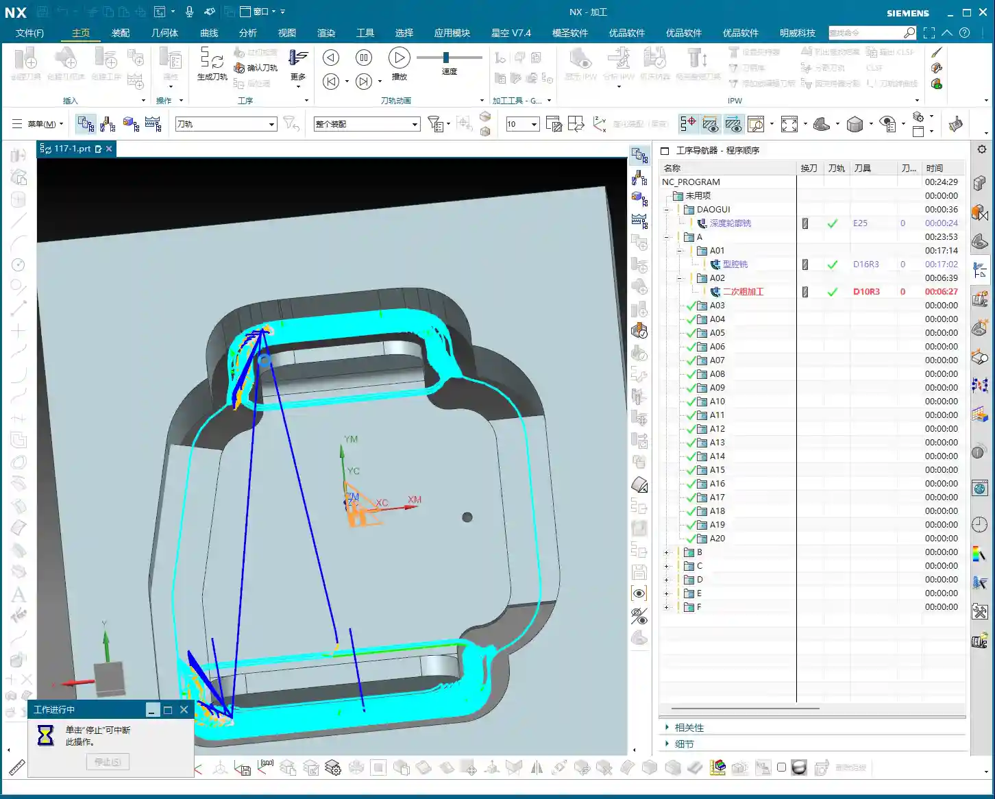
1. **Create Operation**: Similarly, insert a Cavity Mill operation, and select the Rest Roughing mode.
2. **Specify Part and Stock**: The part remains the same, and for the stock, we’ll use the stock model from Layer 100.
3. **Select Tool**: Use the ∅4 R3 bull nose end mill we selected earlier. This smaller tool can reach more areas.
4. **Cutting Parameters**:
* Stock: This time, set the Radial Stock to 0.2mm and the Axial Stock to 0.02mm, leaving just enough for finishing.
* Reference Tool: This is crucial! Set the ∅16 R3 tool used for roughing as the reference tool; this way, NX will automatically identify and machine areas that the ∅16 R3 couldn’t clear.
* Cutting Levels Control: To prevent the tool from machining unwanted surfaces, we can limit the cutting levels to only the surfaces that need machining, ensuring we only sweep the desired areas.
5. **Tool Path Optimization – Addressing Tool Jumps**: After generating the tool path, you might see some areas where the tool ‘jumps’, which isn’t good. I’ve tried the ‘Smooth’ option, but the results were mediocre. Ultimately, I found that changing the cutting method to ‘Follow Periphery’ significantly improved it. Especially for open areas like this, the ‘Follow Periphery’ tool path is much more stable. As for minor tool jumps in small areas, as long as they don’t impact machining quality, letting it clear the base is fine – don’t be too rigid about it.

Local Semi-Finishing: Details Make or Break It
Sometimes, after semi-roughing, a specific area might still have excessive stock or a peculiar shape, requiring additional processing.
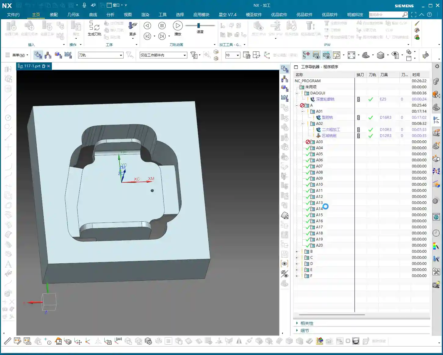
1. **Create Operation**: Again, we’ll use a Cavity Mill operation.
2. **Specify Region**: Box-select this area with excessive stock; we’ll only machine this specific spot.
3. **Tool**: Still using the ∅4 R3 bull nose end mill.
4. **Cutting Parameters**:
* Axial Step: Set it to 0.5mm.
* Stock: 0.2mm.
* Entry Method: Select Outside to Inside; this reduces the impact when the tool enters the material.
5. **Generate Tool Path**: Check it to ensure this area is completely ‘contoured’ clean.
Face Finishing: Surface Finish is King
The final step is to finish machine the flat areas, ensuring both accuracy and surface finish.
1. **Create Operation**: Select a Planar Mill operation.
2. **Specify Part**: Select the flat surfaces that need machining.
3. **Select Tool**: Here, we’ll use a ∅12 R3 bull nose end mill. Flat-bottom tools are highly efficient for machining flat surfaces, and the R3 corner radius also allows for smooth transitions.
4. **Cutting Parameters**:
* Cutting Method: Ensure the method is Tool Flat, meaning you use the flat bottom of the tool to machine.
* Stock: Set 0 Stock. This is a finishing pass, so no stock allowance is permitted.
5. **Generate Tool Path**: Done. This clarifies the entire roughing and finishing process for the part.
Summary: Common Pitfalls and Solutions
Everything we’ve covered today comes from my years of hands-on experience and hard lessons learned; you won’t necessarily find it in textbooks. Here are a few key takeaways. Remember them, and you’ll avoid a lot of headaches down the road:
1. Position the WCS Correctly: While it might not have a huge impact, good habits make you twice as efficient and keep your tool paths clear.
2. Be Flexible with Tool Selection, Distinguish Between Roughing and Finishing Clearly: Use larger tools for roughing to remove bulk material, a slightly smaller tool for semi-roughing and semi-finishing to clear residual material, and select the appropriate tool for finishing to ensure surface finish and accuracy. Don’t expect one tool to do it all; that’s an amateur move.
3. Stock Definition Must Be Accurate: This is the foundation for all subsequent machining; if the stock isn’t defined correctly, your tool paths will definitely have problems.
4. Don’t Be Afraid to Experiment with Tool Path Optimization: When you encounter issues like tool jumps or overcutting, don’t panic. Try different cutting methods (such as ‘Follow Periphery’ and ‘Follow Part’), and adjust your lead-in/lead-out parameters as needed. NX isn’t a one-size-fits-all solution.
5. Stock Control is Key: For roughing, leave sufficient stock for finishing, and for finishing, ensure zero stock is left. This is how you guarantee final dimensional accuracy.
6. Don’t Just Rely on Software Simulation; Develop Your Intuition: Software simulation is a helpful aid, but the actual cutting process – the sparks, chip formation, and machine sounds – those are the real feedback mechanisms. Observe and reflect regularly; that’s how experience accumulates, little by little.
This is all solid, practical advice. Go back, practice hard, and think critically, and soon you’ll also become highly competent, independent experts!
👤 About the Author:
The author is a veteran CNC machining professional with 15 years of industry experience, specializing in UG NX programming. This article is an original work representing personal practical insights.
⚠️ Copyright Notice: Unauthorized reproduction or distribution without prior communication is strictly prohibited.
Leave a Reply