📝 Key Takeaways: ** Master Wang shares his practical expertise in Siemens NX Angle Head Roughing and Semi-Finishing programming. From clever use of program replication and tool axis definition, to the versatile application of 16mm, 6mm, and 10mm milling cutters, he meticulously explains high-efficiency machining strategies for side walls and bottom surfaces. The importance of optimizing non-cutting moves and precise stock definition is emphasized, and he shares how to address accuracy challenges and boost machining efficiency by adjusting parameters, avoiding real-world pitfalls not found in textbooks. **
[VIDEO_HERE]
Master Wang Speaks: The Practical Essence of Angle Head Programming
Listen up, youngsters. Today, Master Wang here is going to give you the real lowdown on **Siemens NX Angle Head Roughing and Semi-Finishing** programming. Don’t think it’s just a matter of clicking a mouse in the software. There’s a lot more to it, all based on hard-earned, practical experience.
Last time, we nailed down the face milling (planar) programs. Now, we’re moving on to side milling. To be frank, side milling has many similarities with face milling programming. Especially for these areas, the principles are much the same. Learn one, and you can apply it to others with minor parameter adjustments. But don’t underestimate those “minor adjustments”; there’s a world of knowledge in them.
Smart Use of Replication: Batch High-Efficiency Programming
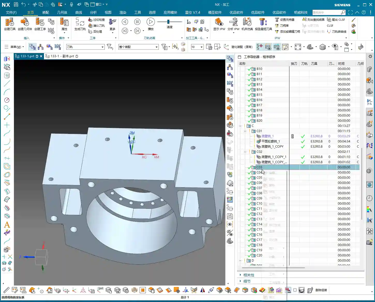
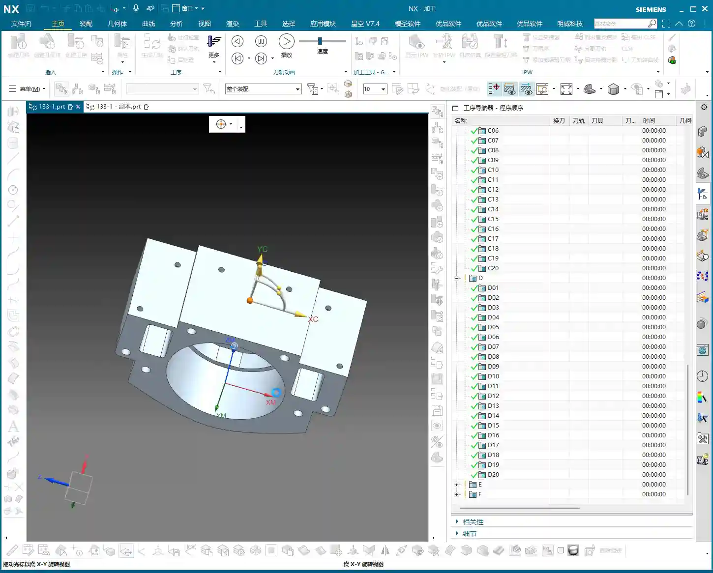
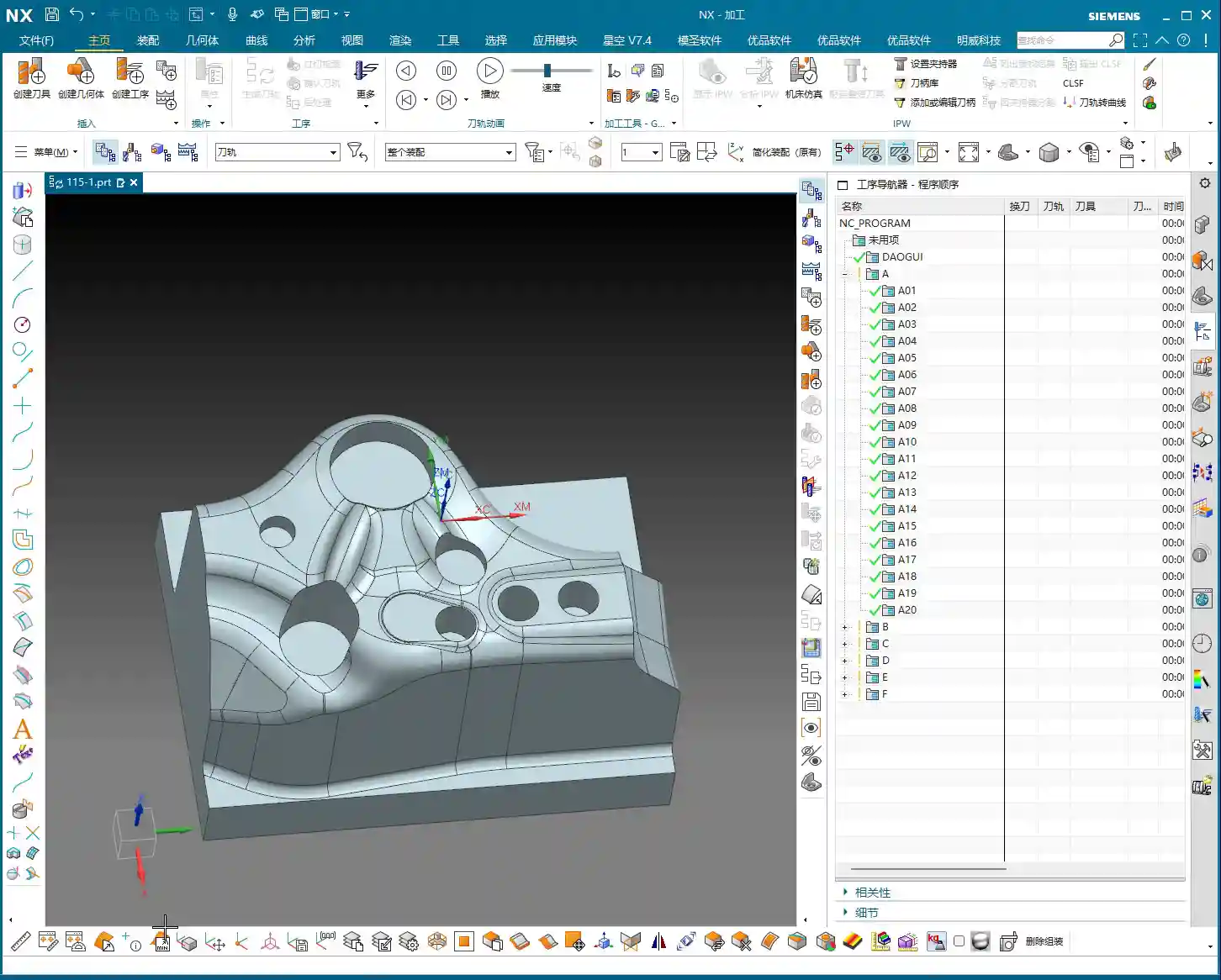
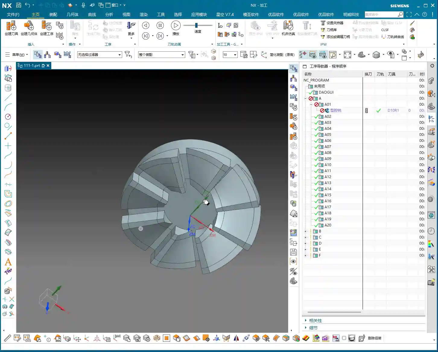
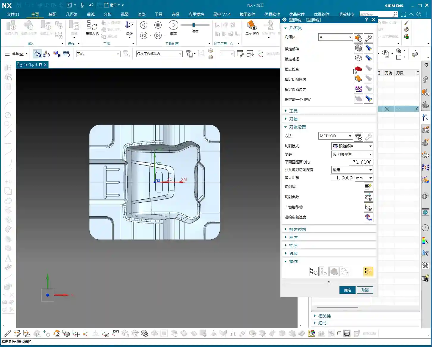
For us programmers, efficiency comes first. For the same batch of parts, especially for symmetrical or structurally similar areas, the best method is to **replicate an existing program and then modify the key parameters**. This saves time and effort, and reduces the chance of errors. Then, with a transformation function, *whoosh*, the program is replicated to the other side. How convenient!
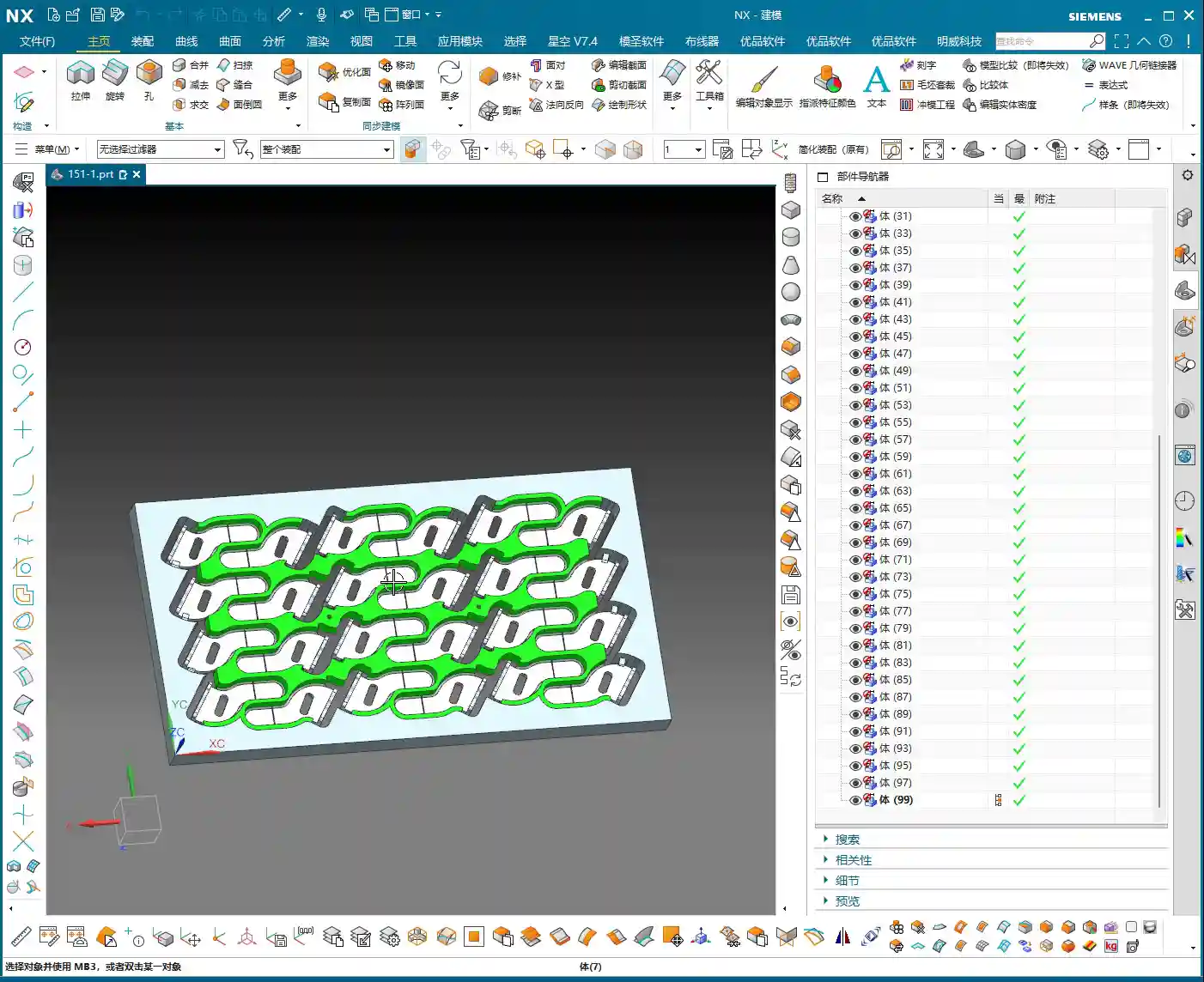
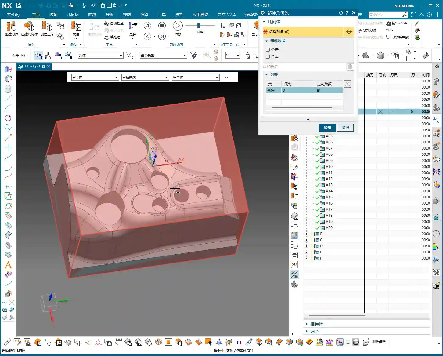
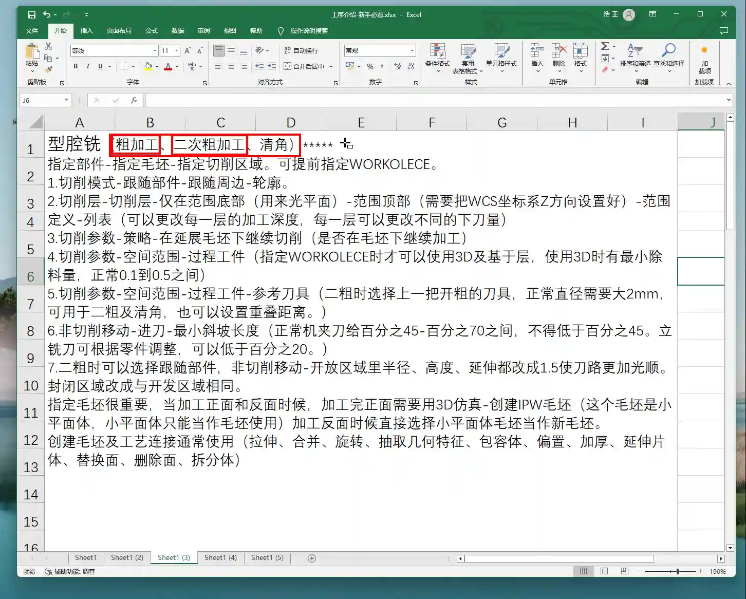
Let’s start with one of the side surfaces. This program might seem simple on the surface, but to do it properly, you need to pay attention to the details. First, make a copy of our previous face milling roughing program, or directly copy it into a new operation set. Program by region to keep things organized.

Angle Head Roughing: 16mm End Mill Leads the Charge
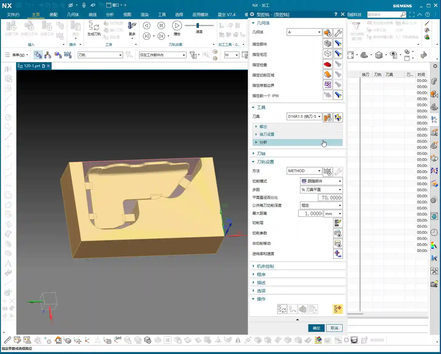
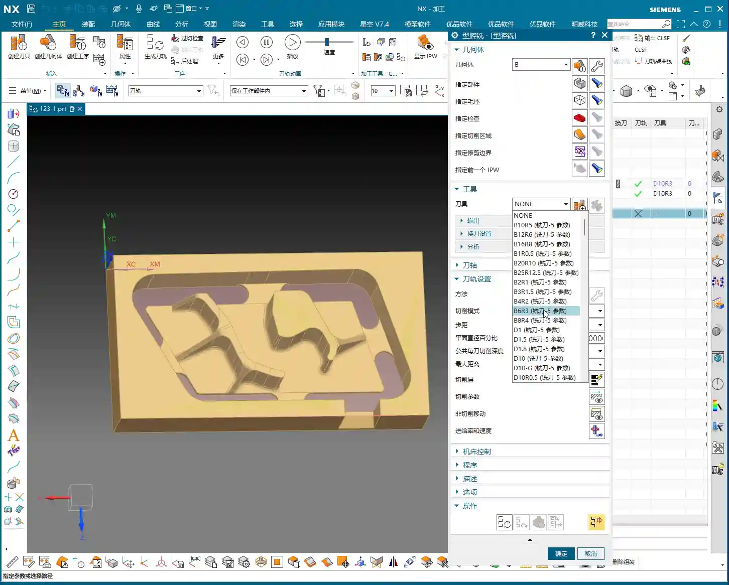
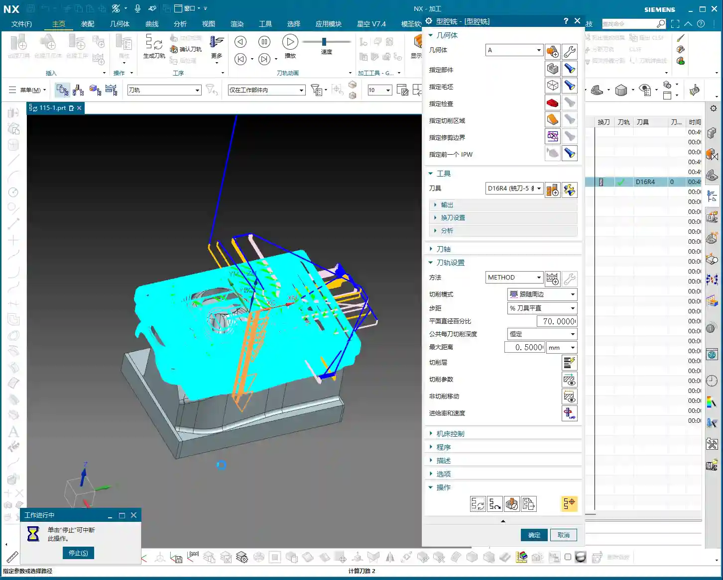
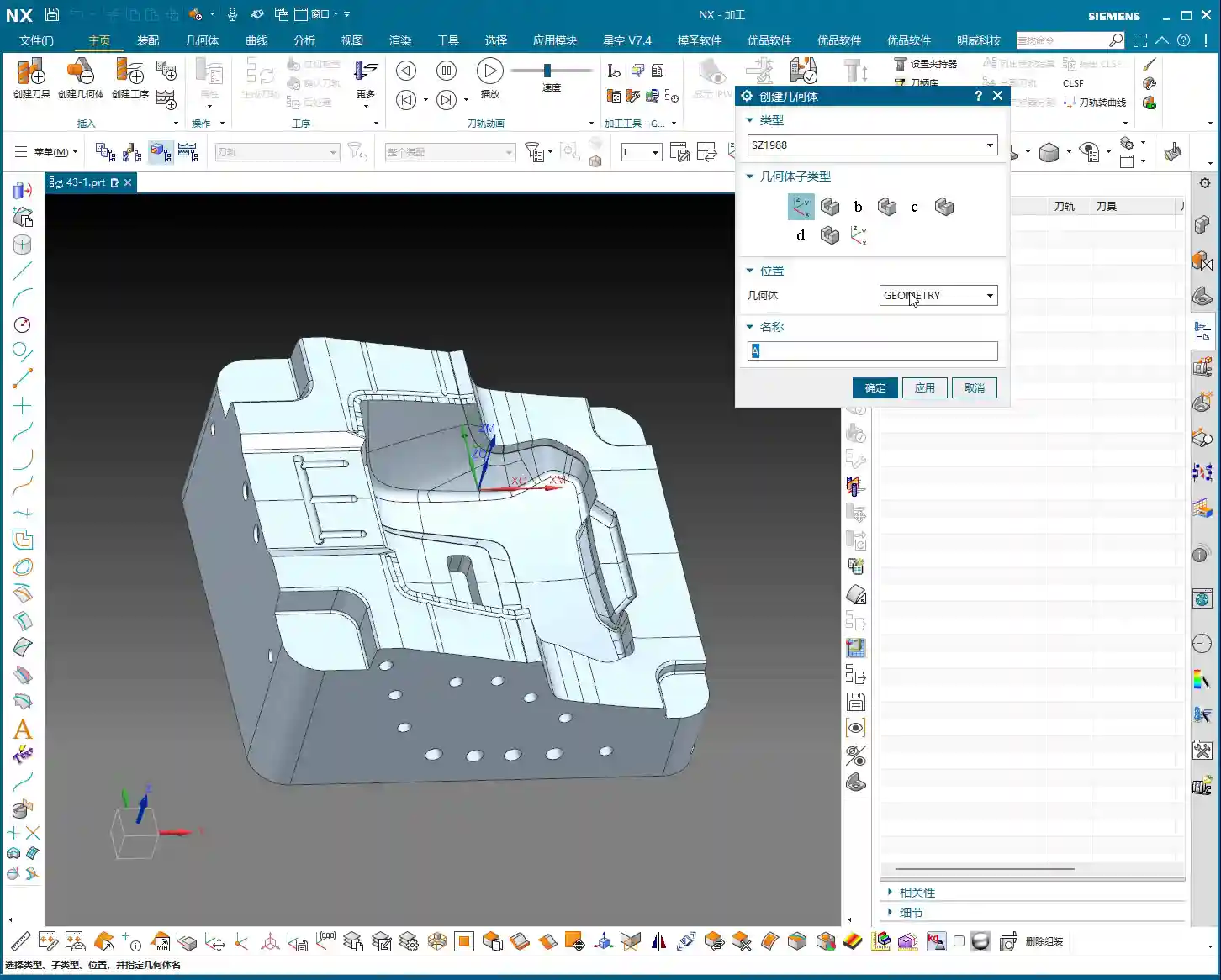
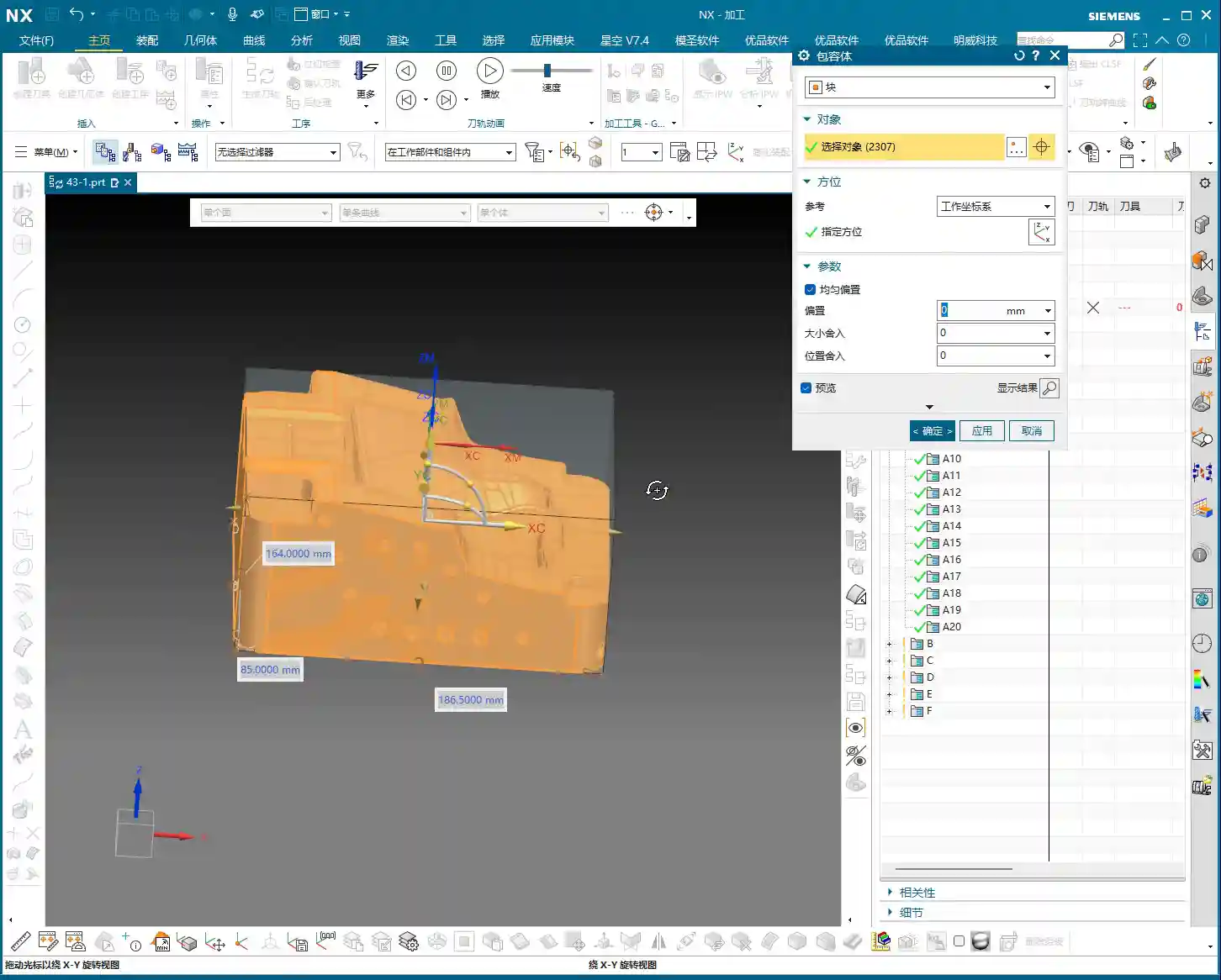
For roughing this area, listen up. When we’re using a **HMC (Horizontal Machining Center)**, many programs are actually executed in a single setup. For instance, use a **16mm diameter end mill** to clear out the bulk of the material first.
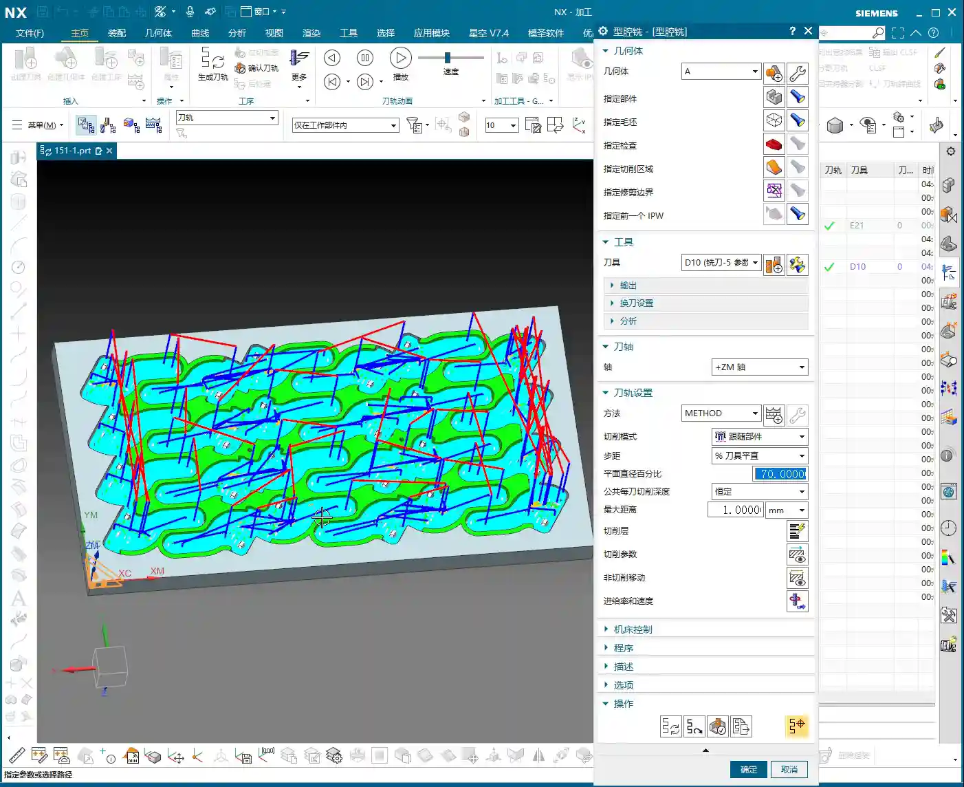
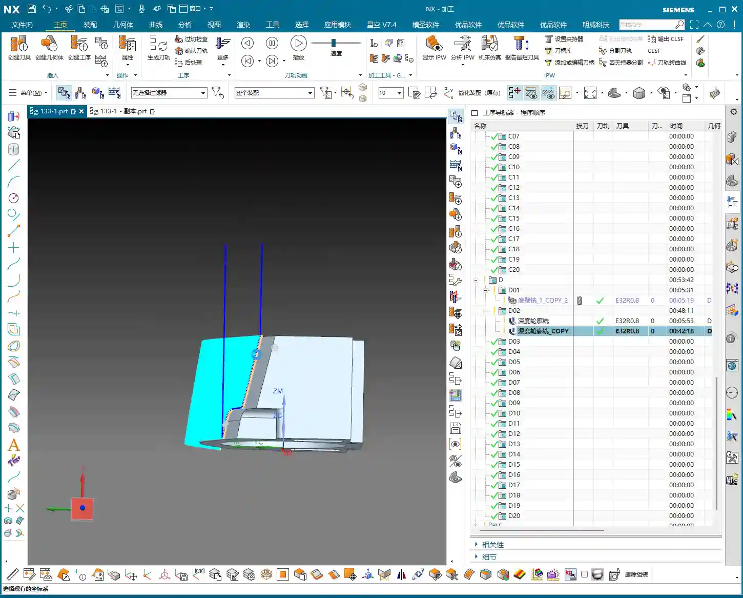
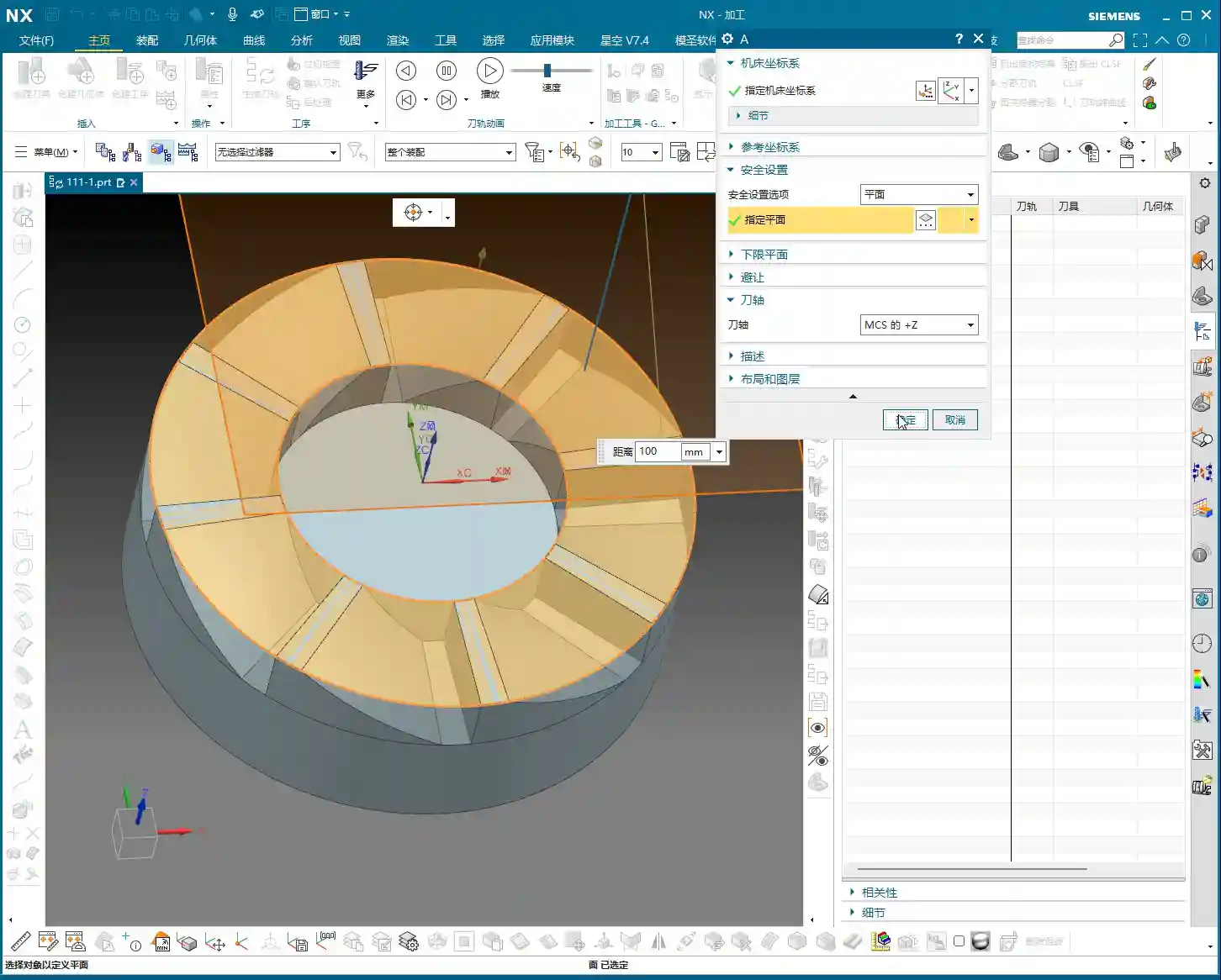
Open the replicated program; don’t worry about other settings for now. The most critical step is to correctly specify the tool axis direction. For an angle head, the tool axis must be horizontal. Click on the surface you intend to machine, letting the software automatically determine the tool axis, or manually adjust it to the desired direction. Then, generate the toolpath directly and observe the result.
This first step is about clearing the majority of the stock. Don’t expect to achieve a finished surface in one pass; that’s unrealistic and prone to chipping or breaking the tool. Roughing prioritizes efficiency and safety, leaving sufficient material for subsequent finishing passes.

Angle Head Semi-Finishing and Bottom Surface Corner Cleanup: 6mm End Mill for Finer Work
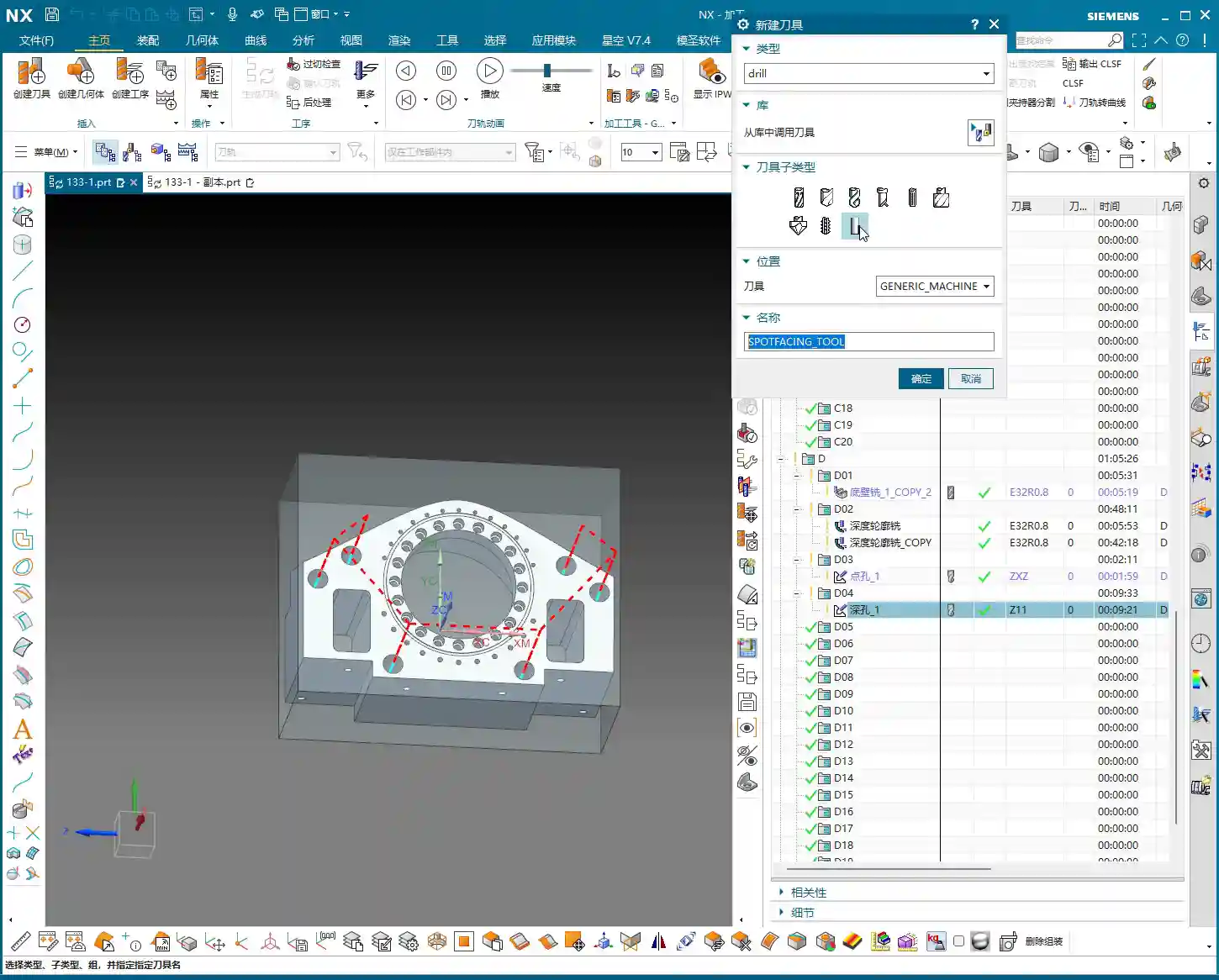
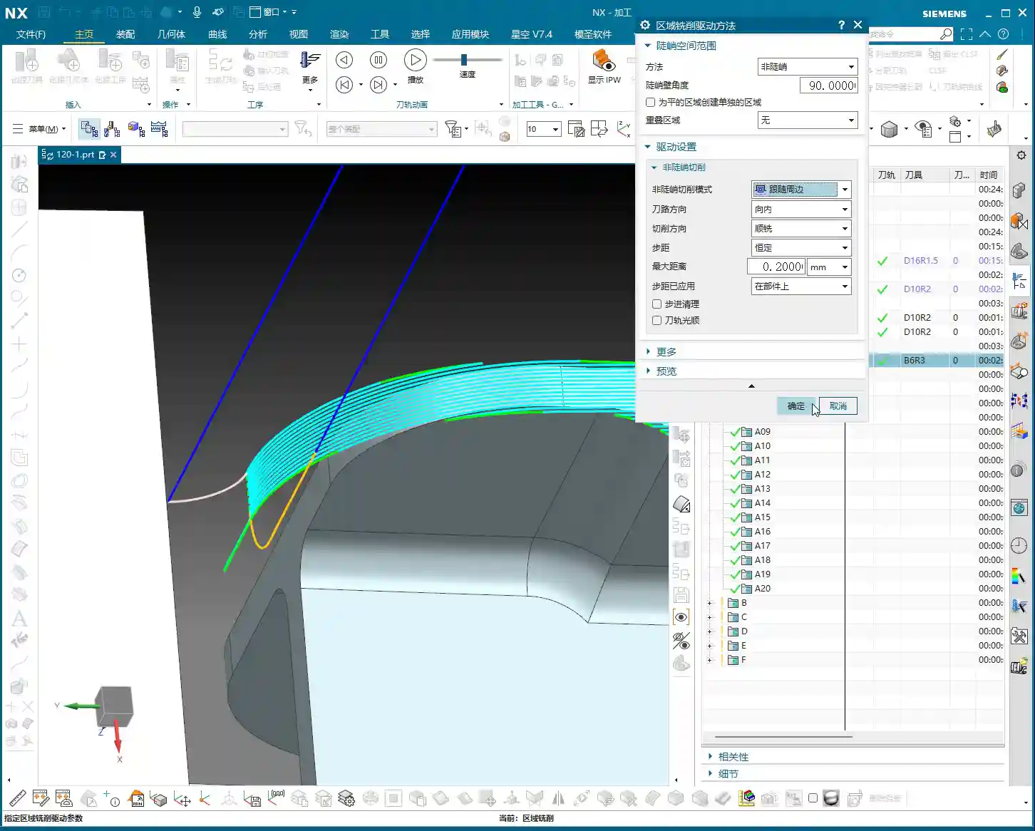
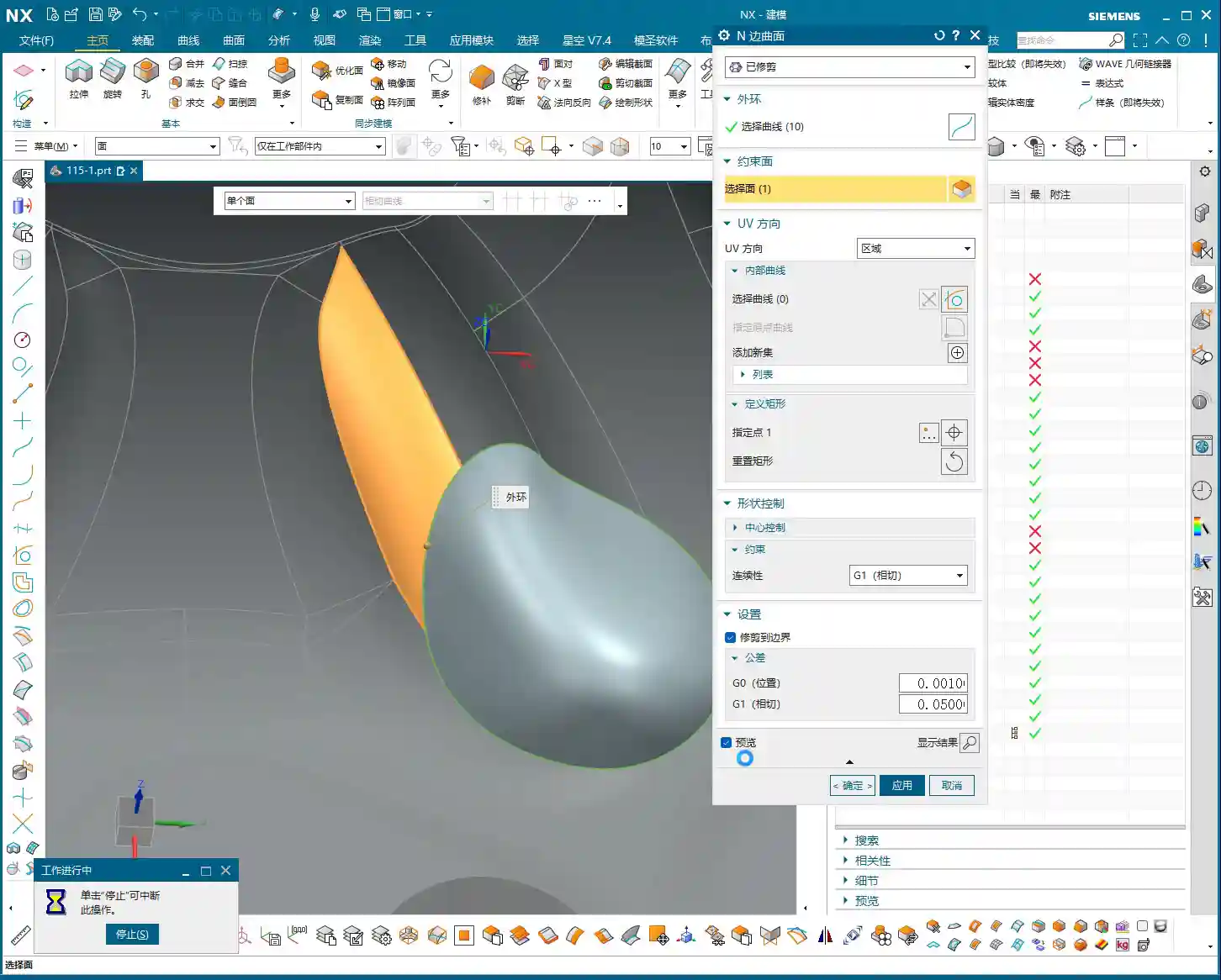
After the 16mm tool has cleared the main surfaces, there will always be areas it can’t reach, especially small radii or narrow gaps. At this point, you’ll need to switch to a smaller tool for semi-finishing or corner cleanup. We usually follow up with a **6mm diameter end mill**.
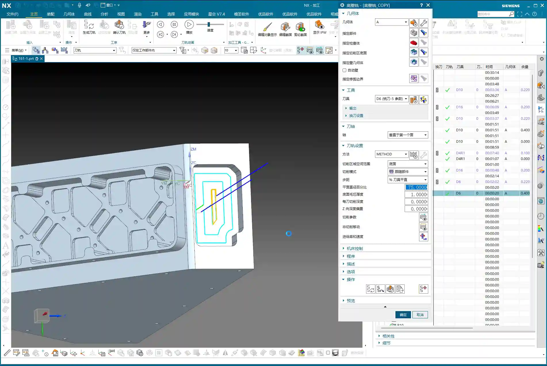
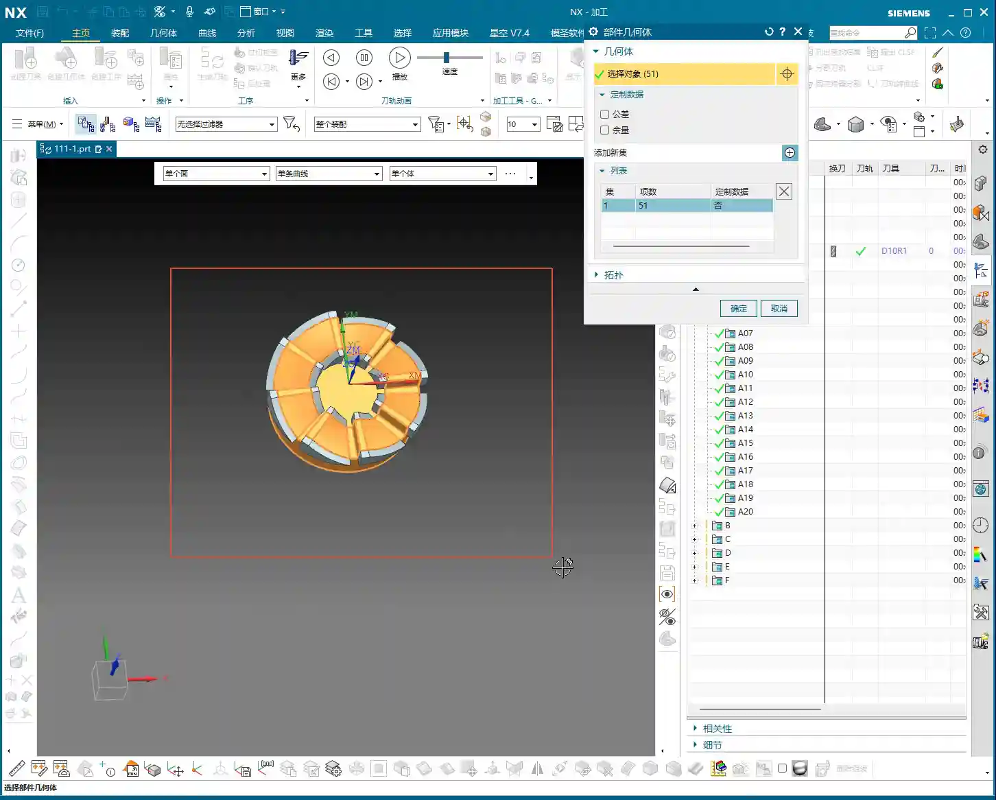
Similarly, replicate the previous program again. Change the tool axis and the tool. Remember, switch to a **6mm tool**, and keep the tool axis direction consistent. Directly select the side or bottom surface you want to machine, and let it clear out the remaining stock in those areas. This program is very simple; as long as the tool axis and tool are correct, it should generate without issues.
Next is the bottom surface. The 6mm tool just used can also be employed to clean up the bottom surface, bringing it to a semi-finished state. This ensures the flatness and accuracy of the bottom surface, preparing it for the subsequent finishing pass.

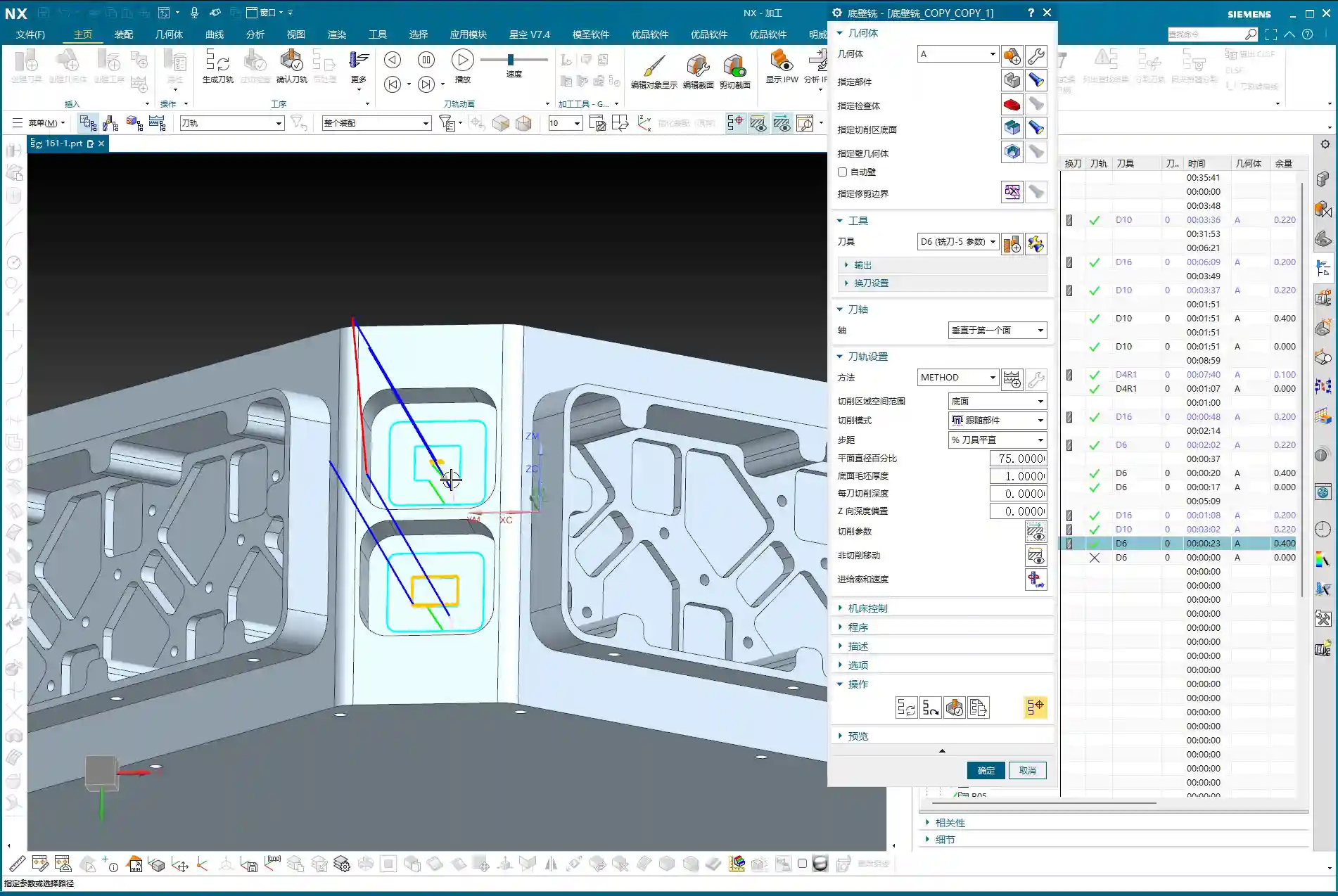
Side Wall Corner Cleanup and Contour Finishing: Multi-Pass Machining and Non-Cutting Move Optimization
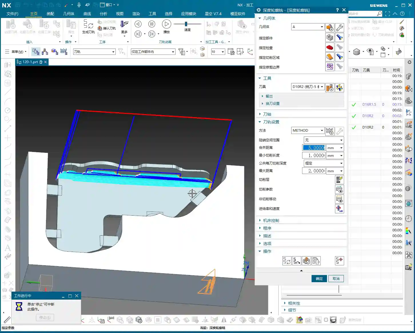
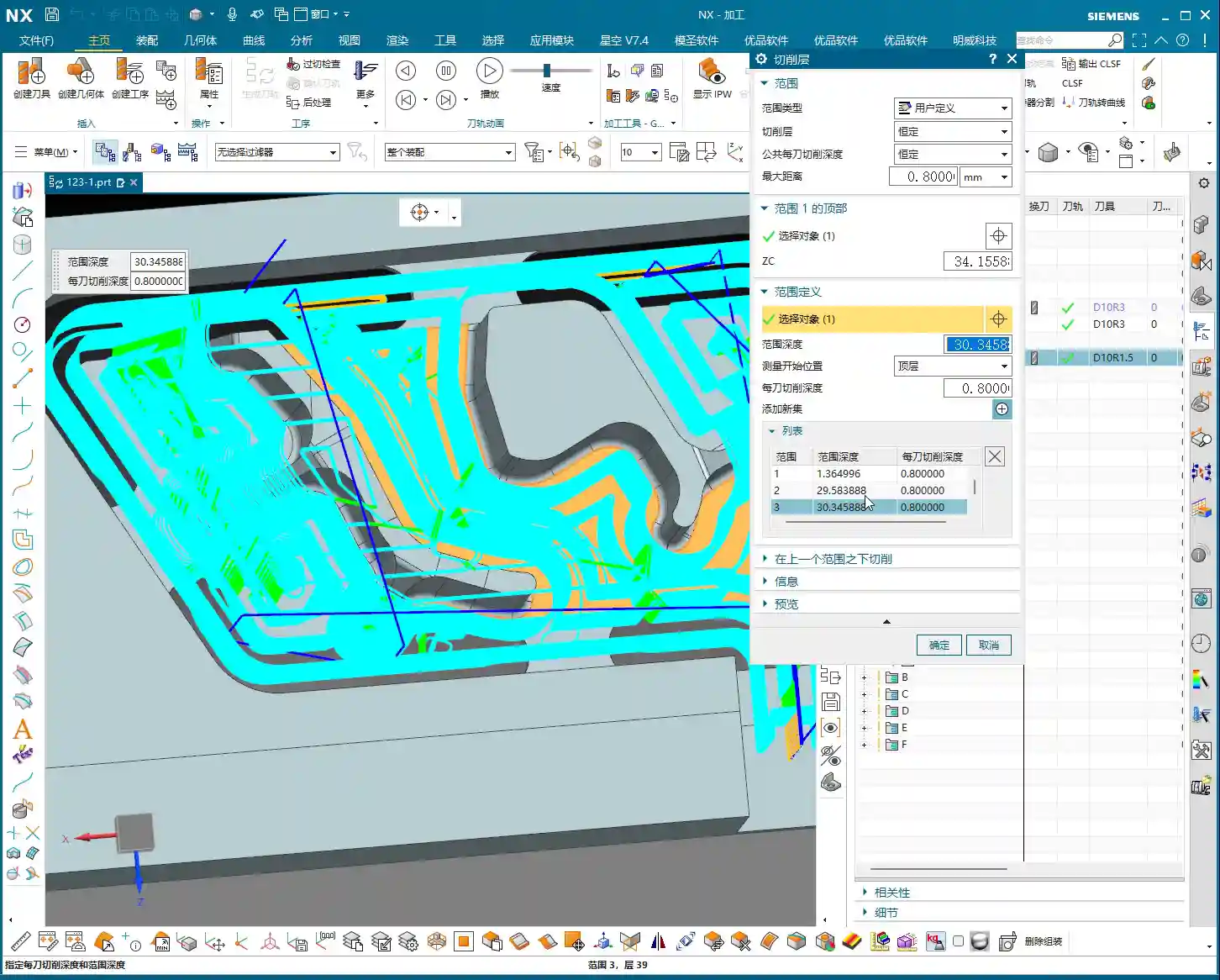
Just having a clean bottom surface isn’t enough; side wall corner cleanup is also critical. If you want to go full depth in one pass and include the side walls with the bottom surface finishing program, that’s fine. However, if high accuracy is required or the cutting depth is significant, **multi-pass machining** is recommended.
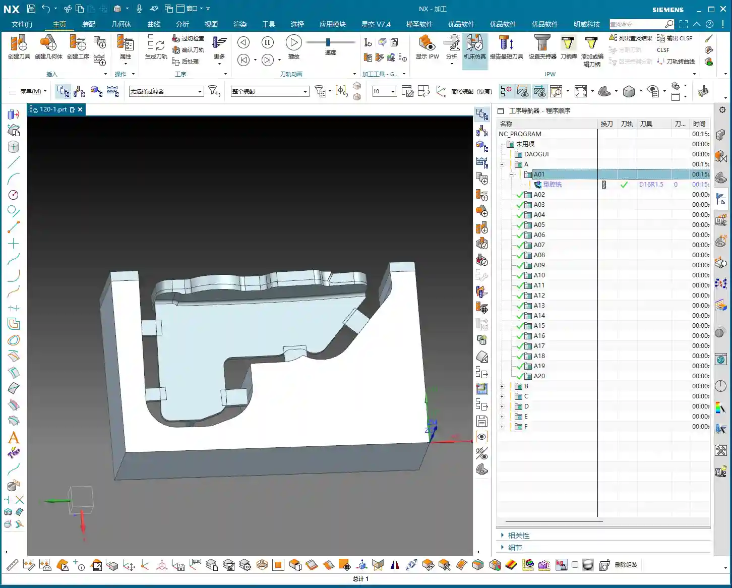
At this point, we can use the “Contour Milling” or “Cavity Milling” functions. First, measure the depth of this side wall, say it’s **10mm**. Then we can choose to machine in two layers, with a Depth of Cut (DOC) of **5mm** per layer. This ensures both cutting stability and effective corner cleanup.
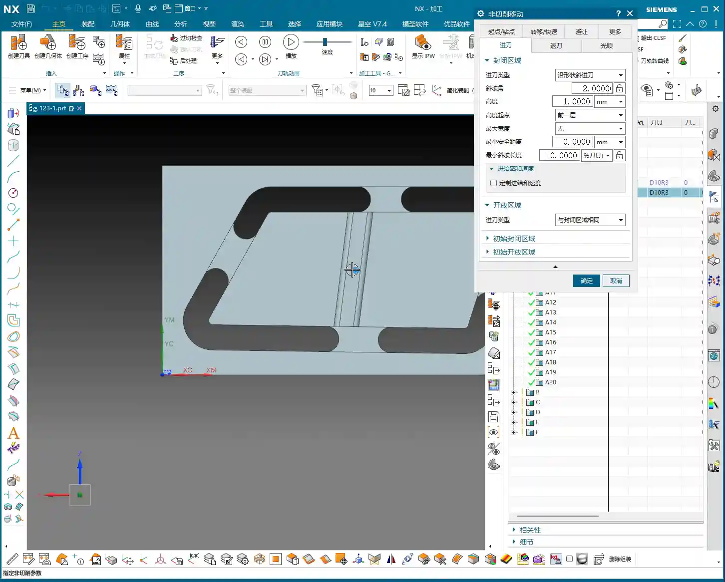
Here’s a little trick, especially when machining areas with open boundaries: the settings for non-cutting moves (retracts and approaches) are crucial. Change the closed type in non-cutting moves to **“Same as Open Area”**, and then set the arc radius for open areas to **1 or 2mm**. This way, the tool will follow an arc when entering and exiting cuts, avoiding direct retraction into walls. This protects the tool, ensures machining quality, and reduces the risk of scratching.

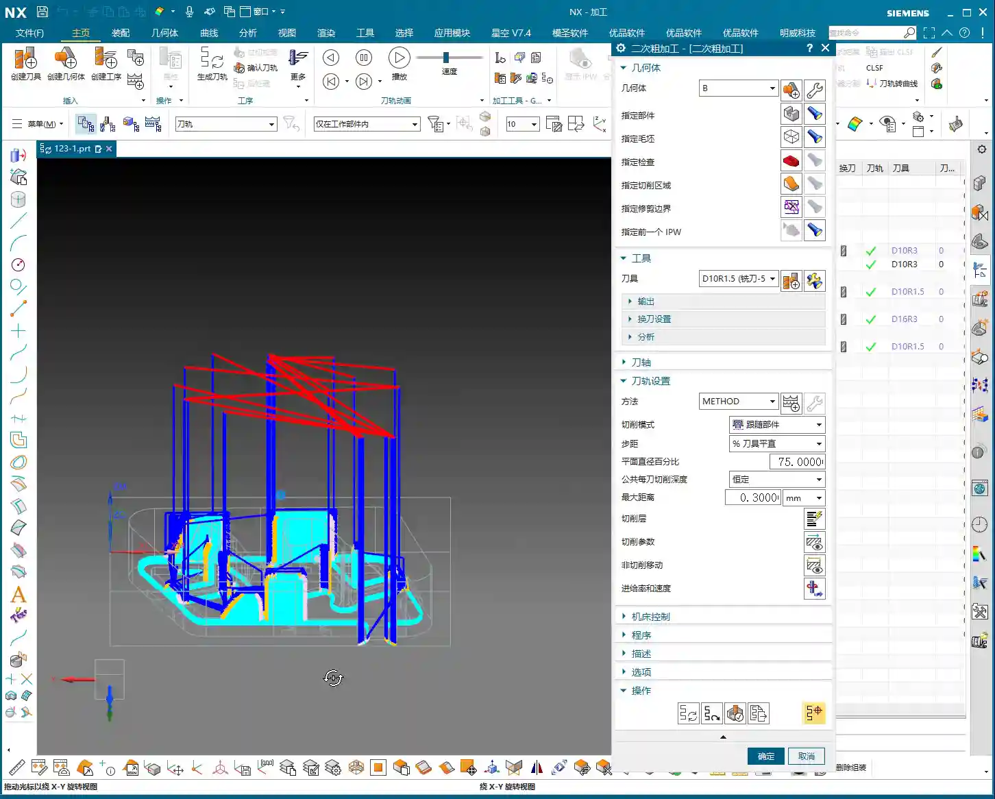
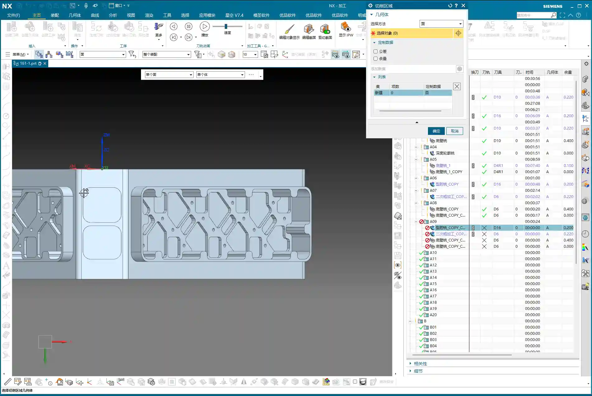
Corner Cleanup for Complex Areas: 10mm End Mill Returns
After the 6mm tool has semi-finished most of the side walls and bottom surfaces, some larger radii or deep hole edges might still require a slightly larger tool for further corner cleanup, to prevent steps or remaining stock. This is where a **10mm diameter end mill** comes into play.
The procedure is the same as before: replicate the program, change the tool to 10mm, and re-select the machining area. While it’s all about corner cleanup, selecting the appropriate tool based on different geometries and tool radii is crucial. Use a larger tool for larger radii for higher efficiency; only use a smaller tool for smaller radii to avoid unproductive air cutting.
Master Wang’s Expertise: Proper Stock Allowance and Toolpath Adjustment
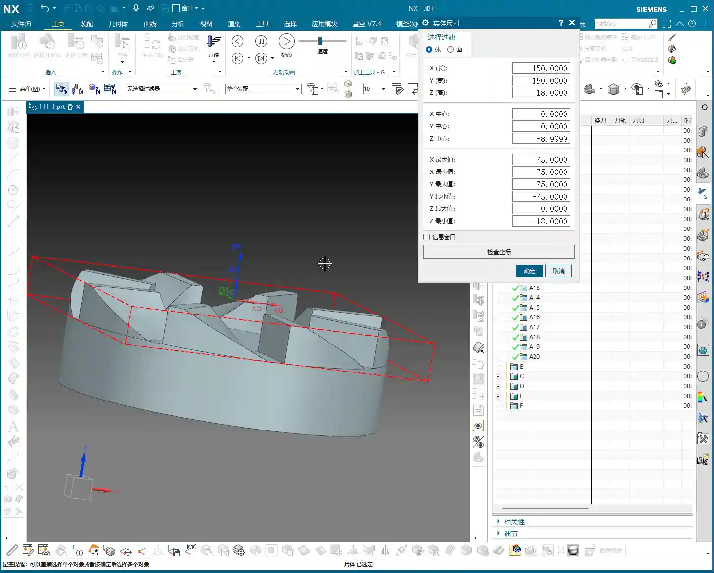
When performing corner cleanup and finishing passes on side walls, stock allowance (how much material to leave for the next tool or next pass) is a delicate matter. Sometimes, you’ll find that once a program is generated, the toolpath doesn’t look quite right, or certain areas aren’t cleanly machined. This is likely due to an improperly defined stock (or remaining stock from the previous operation), or toolpath parameters that haven’t been adequately tuned.
For instance, sometimes to allow the tool to cut into corners more effectively, we need to adjust the tool tilt angle or the toolpath offset. I once encountered an area where I experimented with **78 degrees, 90 degrees, and even 85 degrees**, iterating until I found the optimal cutting angle that both cleaned the corner thoroughly and didn’t overstress the tool. These are all insights gained from experience. Don’t just rely on software simulations; observe the cutting sparks and listen to the machine’s sound!
If one tool can complete the finishing pass for both the bottom surface and side walls simultaneously, that’s ideal. This reduces tool change time and improves efficiency. However, the prerequisite is that the tool geometry must match the part geometry. Don’t sacrifice accuracy for convenience.
Summary: Pitfall Avoidance Guide
1. **Tool axis direction is the lifeline of angle head programming**: Always ensure the tool axis is parallel to the side surface; otherwise, you’re wasting tools and material.
2. **Proceed in stages, don’t rush**: First, use a large tool for roughing, then smaller to medium tools for semi-finishing and corner cleanup. Progress step-by-step to ensure safety and accuracy.
3. **Clever use of replication and transformation**: For similar areas, directly replicate the program, modify parameters, and then use the transformation function for rapid generation, boosting efficiency.
4. **Non-cutting moves are key for optimization**: Arc-shaped entry and exit moves in open areas effectively protect the tool and prevent workpiece scratches.
5. **Stock definition must be accurate**: A clear stock definition is the foundation for generating appropriate toolpaths.
6. **Observe, reflect, and don’t blindly follow software**: Software simulations are static; shop floor conditions are dynamic. Frequently observe cutting conditions and adjust parameters promptly. Sometimes you might feel a 16mm tool is too large, and a 10mm tool might be more suitable for roughing; this is called “adaptive application.”
👤 About the Author:
The author is a veteran CNC machining professional with 15 years of industry experience, specializing in UG NX programming. This article is an original work representing personal practical insights.
⚠️ Copyright Notice: Unauthorized reproduction or distribution without prior communication is strictly prohibited.