Tag: Surface Milling

  • Siemens NX Surface Driven Machining Masterclass: Master Wang Helps You Conquer Diagonal Point and UV

    📝 Key Takeaways:

    Siemens NX Surface Driven Machining in Practice

    Surface Driven Machining: Practical Application to Prevent Issues

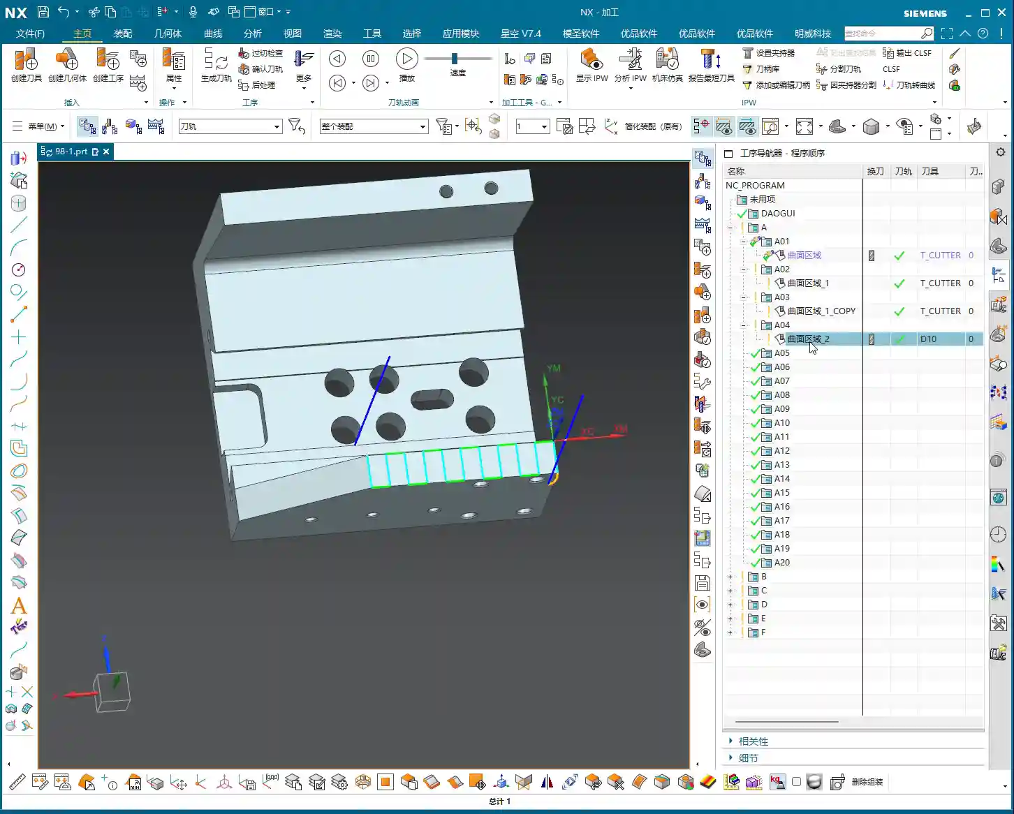
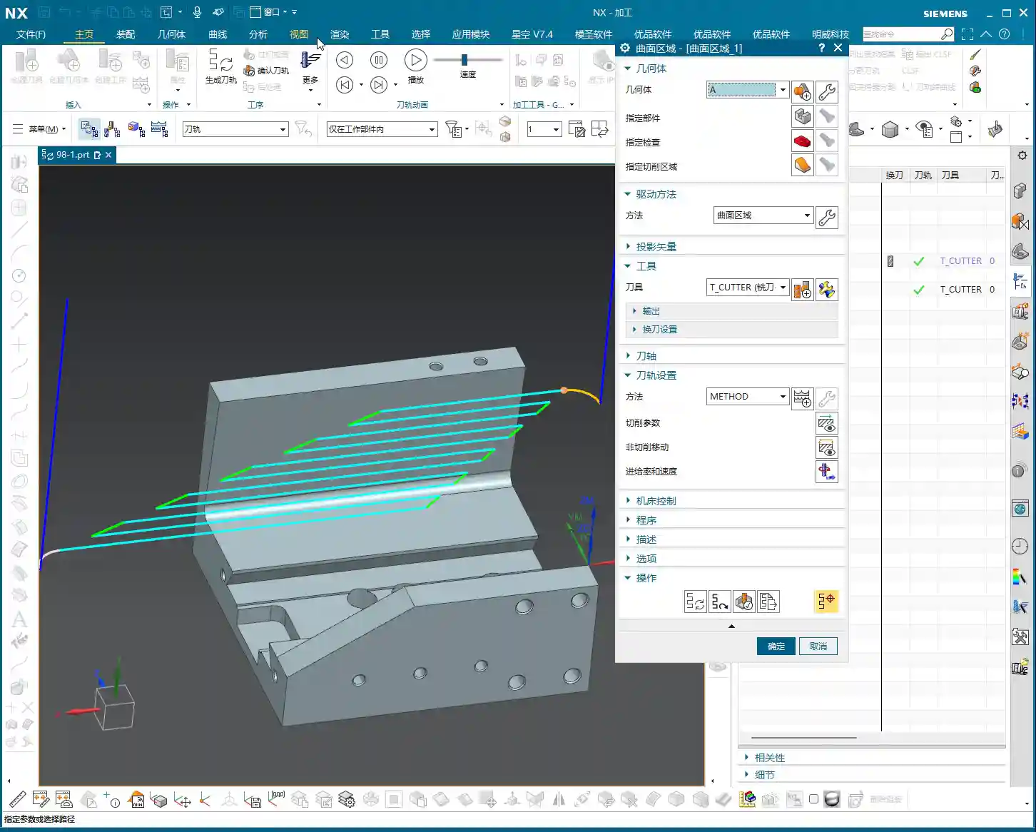
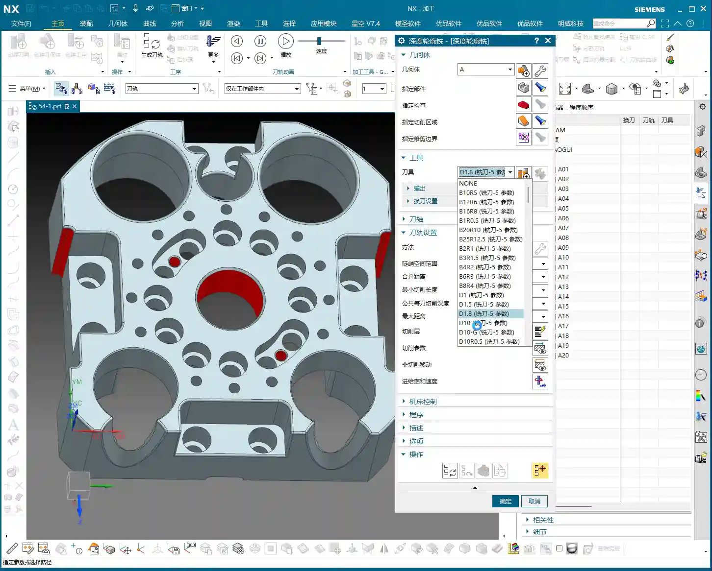
    Basic Operations: Face Selection and Direction

    Listen up, lads! Today we’re diving deeper into Siemens NX’s Surface Driven machining. This stuff looks simple, but there’s a lot more to it than what you’ll find in any textbook.

    First off, the most fundamental step is selecting the **drive geometry**. You pick the face, and that’s the face that gets machined – no surprises there. But you gotta watch the direction carefully. Sometimes, if the direction is wrong, the generated toolpath will be reversed, and you’ll scrap the part! You’ll have to manually “reverse” it. It’s the same principle as when we’re doing a “Finishing pass” on a flat surface, right?

    The Stepover also needs to be set correctly. Don’t just rely on default values; those are just for show. For actual machining, you need to determine it based on your tooling, material, and required surface finish. For example, if you’re doing a Finishing pass on aluminum, a larger Stepover might be fine. But for titanium alloys or nickel-based superalloys, you need to be extremely careful; even a slightly larger Depth of Cut (DOC) can chip the tool. And custom grinding a non-standard tool isn’t cheap!

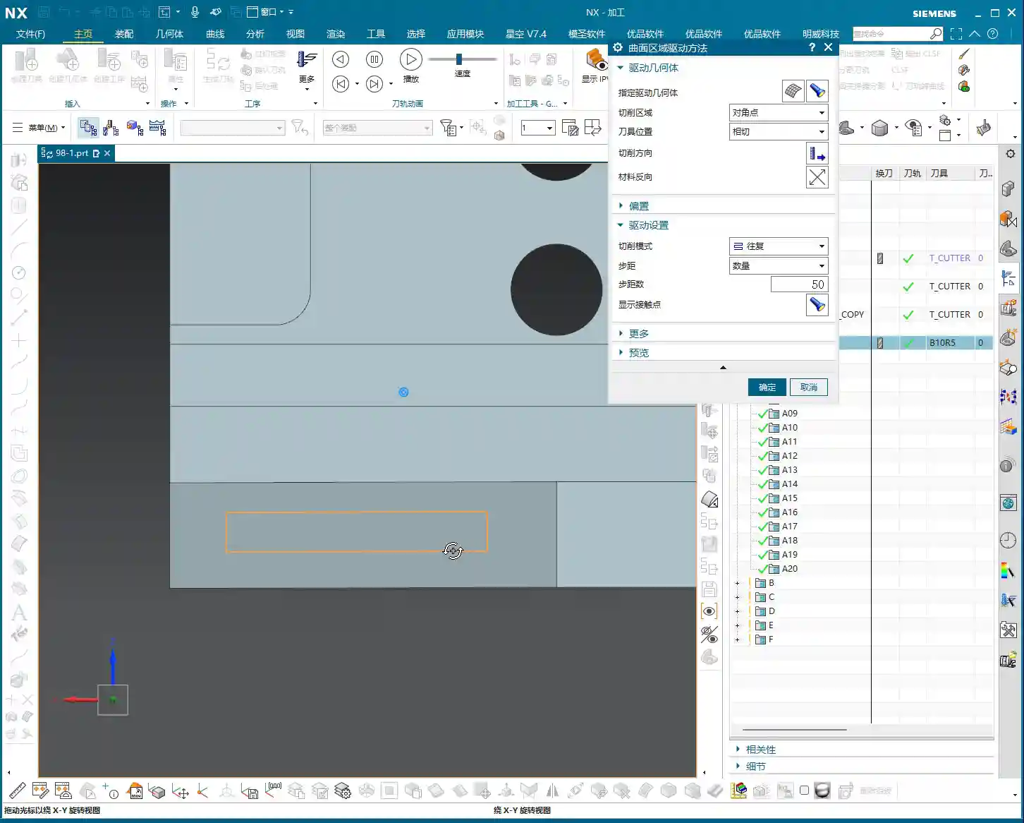
    Core Technique: The Secrets of Diagonal Point Drive

    Next, let’s look at the “Diagonal Point” mode. This feature might not be something you use often, but it can be a lifesaver in critical situations. It lets you select two diagonal points to define the machining area. For instance, if you only want to machine a small rectangular section on a face, just box it in!

    In actual production, however, I, Old Wang, generally recommend using Surface Percentage more often. For the Diagonal Point mode, just understand its principle: it helps you define a machining range using two points. But don’t expect it to do too many fancy tricks. Most of what it can do, Surface Percentage can also achieve, and often with greater flexibility.

    Remember one thing: these modes are just tools. The key is in your head – knowing what needs to be machined and what the most efficient way to do it is.

    The Art of Boundary Constraints (Check Surfaces): Safety and Efficiency are Paramount

    Why Do Overcuts Occur? The Importance of Check Surfaces

    Alright, listen up, because this next point is absolutely critical! How many times have I told you guys: you MUST select your Machining Boundaries (what Siemens NX calls “Check Surfaces”) properly! Otherwise, the toolpath will run wild like a runaway horse, and “snap!” – you’ll overcut in corners or along edges! Every scrapped part in your shop is hard cash down the drain, far more expensive than a few extra mouse clicks!

    If you don’t select Check Surfaces, the toolpath will follow the maximum extent of the drive geometry. As soon as any area exceeds the predefined machining range, you’re asking for trouble. This is especially true for complex surfaces; one lapse in attention and you’ll “mill right through” the part. This is no joke.

    Select All? Absolutely Not!

    Some folks try to save time by selecting all faces as Check Surfaces, thinking it’s the safest approach. Wrong! Dead wrong! I’ve said this many times before: doing that can easily mess up your toolpath, resulting in a completely disorganized program! This happens because when the drive geometry is projected, it considers all Check Surfaces, which can sometimes conflict with each other, leading to chaotic path planning.

    So, be selective! For whichever area you’re machining, only select the boundaries for that specific region. Don’t be greedy. Striving for precision is our duty in machining.

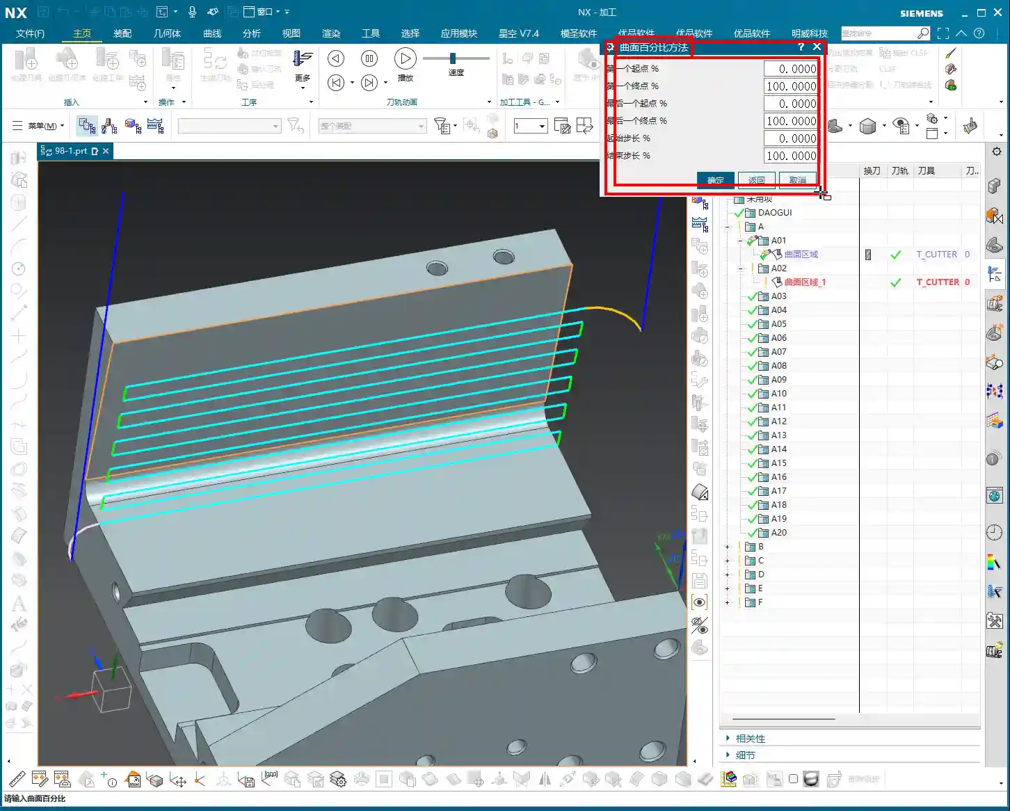
    The Key to Undercut Machining: The Clever Use of Surface Percentage

    This Surface Percentage feature is truly a powerful tool when machining special geometries, such as undercut faces or sidewalls! It allows you to extend or shrink the boundary of your selected drive face by a percentage. Especially for undercuts, if you use traditional toolpaths, you’re very likely to experience tool collisions or poor results. But with Surface Percentage combined with the right parameters, the results are outstanding!

    Furthermore, it’s very much like what we often refer to as “Finishing pass on a flat surface” or “Finishing pass on a sidewall.” Many times, a single Surface Driven operation can replace several dedicated toolpath commands, instantly boosting your efficiency.

    Direction and Projection: The Physical Logic Behind NX Toolpaths

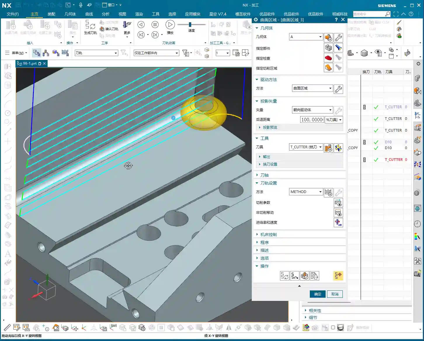
    Drive Geometry Projection: Precisely Locating the Machining Area

    With NX, much of the time you’re essentially dealing with “projection.” The drive face you select will be projected onto the machining area according to your set “direction.” This projection direction dictates the direction your tool will descend. If your direction is wrong, the projected machining area will be completely different from what you envisioned!

    Especially the option “Project to Drive Geometry”: it doesn’t just cut simply from top to bottom. Instead, the tool’s projection direction aligns with the drive geometry. When machining certain angled or curved surfaces, this ensures the tool cuts perpendicular or at an angle to the surface, leading to better cutting performance and extended tool life.

    “Retract Distance”: A Trap in Small Hole Machining

    Here’s another pitfall: the “Retract Distance”. This feature provides a safe clearance for the tool during drive face projection to prevent collisions. If you’re machining a relatively small hole and this Retract Distance is set too large, the tool might not even be able to enter the hole, making it impossible to machine!

    Therefore, when dealing with small holes or narrow areas, always check and adjust the Retract Distance according to the actual situation. Don’t just set it blindly! Attention to detail determines success or failure; these are lessons learned the hard way in the shop, paid for with sweat and blood!

    The Powerful Combination of Percentage and Boundaries: Precise Toolpath Control

    Flexible Use of Percentage: Extension and Limitation

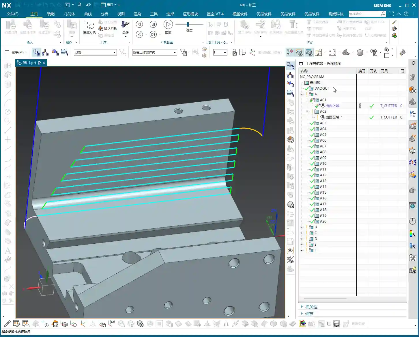
    When you use Check Surfaces and Percentage together, that’s when things get powerful! For example, if you set a negative percentage (e.g., -20%), the toolpath will shrink inward. Set a positive percentage, and it will extend outward. But will this extension cause an overcut? That depends on how accurately you’ve selected your Check Surfaces.

    Once you’ve selected Check Surfaces, the toolpath will obediently stay within those boundaries and won’t extend further. It’s like drawing a cage for the toolpath; it can’t escape. So, by flexibly applying Check Surfaces and Percentage, you can precisely control the toolpath, directing it exactly where you want it to go and preventing it from going where you don’t.

    Summary: Pitfall Avoidance Guide

    Listen up, lads, everything I’ve taught you today is based on 15 years of hard-won experience. Siemens NX’s Surface Driven capabilities are powerful, but don’t operate blindly.

    First, ALWAYS check the drive direction! You absolutely must verify the toolpath’s orientation. If it’s reversed, correct it; don’t just assume it’s right.

    Second, Machining Boundaries (Check Surfaces) are your safety valve! Selecting them correctly prevents overcutting. Don’t select all, and don’t pick them randomly. If you’re unsure, it’s better not to select any, but then you absolutely must meticulously check the toolpath simulation afterward.

    Third, parameters are NOT fixed! Values like “Retract Distance” and “Percentage” must be applied dynamically based on your workpiece, tooling, and material. It’s not a one-size-fits-all solution; don’t just stick to whatever the textbook says.

    Finally, simulation is fundamental, but practical application is the real test! Don’t just rely on a perfect computer simulation. Before hitting the machine, mentally run through the process, observe the cutting sparks, and listen to the tool’s sound – that’s where true expertise lies!

    Remember, in this business, efficiency and cost-effectiveness are the absolute truths. Every part not scrapped, every extra minute of machining time, translates directly to profit! This isn’t just a technical skill; it’s also about business acumen.

    👤 About the Author:
    The author is a veteran CNC machining professional with 15 years of industry experience, specializing in UG NX programming. This article is an original work representing personal practical insights.

    ⚠️ Copyright Notice: Unauthorized reproduction or distribution without prior communication is strictly prohibited.

  • Siemens NX CAM Surface Drive Percentage: Master Wang Teaches You How to Refine Toolpaths, Ditch “Bli

    📝 Key Takeaways: Master Wang personally reveals the practical secrets of Siemens NX CAM’s Surface Drive Percentage! Master the cutting direction and the synergy of six key parameters to precisely control toolpath start and end points, as well as boundary trimming and extension. Effortlessly manage stock allowance for roughing and finishing passes, significantly boosting machining efficiency and part accuracy. Say goodbye to guesswork programming, and take control of both cost and efficiency!

    Hello everyone, I’m Master Wang!

    Today, let’s talk about a particularly practical feature in Siemens NX CAM—Surface Drive Percentage. Textbooks might give you a few concepts, but in our actual work, this feature is crucial for refining toolpaths and boosting both efficiency and accuracy. Listen up, because these are “hardcore” insights I’ve gained from over a decade of hands-on experience at the machine!

    Core Concept: What Exactly is Surface Drive Percentage?

    Simply put, Surface Drive Percentage allows you to precisely control the start point, end point, and extension or trimming along the edges of your toolpath on the drive surface. Don’t underestimate these percentages; when used effectively, your toolpaths will run smoother, machining efficiency will be higher, and part accuracy will be better assured. It’s like drawing a “racetrack” for your tool, telling it where to start, where to stop, and even allowing it to run slightly off the track or finish early.

    Cutting Direction: The “Compass Needle” Determining the Start Point

    Before we dive into percentages, I must emphasize an absolutely critical prerequisite—the cutting direction. The cutting direction you choose directly determines where your “first start point” actually is!
    For instance, if you choose to cut from left to right, then the left side is the start point. If you reverse it to cut from right to left, then the right side immediately becomes the start point. Therefore, every time you adjust the percentages, always confirm that your cutting direction is as expected. Otherwise, you might spend ages adjusting percentages, only to find the results aren’t what you envisioned—because the start point itself has changed!

    Six Key Parameters: The “Scissors” for Toolpath Length and Boundaries

    Unlike “Streamline” operations, which typically only have four parameters, Surface Drive Percentage offers six parameters. These six parameters are divided into two categories: one controls the overall length of the toolpath, and the other controls the toolpath’s extension or trimming along the boundaries.

    1. Toolpath Length Control:

    * First Start Percentage
    * The default value is 0. Setting it to 0 means starting from the beginning of your chosen cutting direction.
    * If set to 20, the toolpath will start cutting 20% inward from the start point, leaving the first 20% untouched.
    * If set to -10 (a negative number), the toolpath will extend outward by 10% from the start point. This is extremely useful in specific situations, such as avoiding clamping elements or allowing the tool to enter the cut in a more stable condition.
    * First End Percentage
    * The default value is 100. Setting it to 100 means machining along the cutting direction all the way to the end of the drive surface.
    * If set to 50, the toolpath will only machine up to 50% of the total length and then stop.
    * If set to 120, the toolpath will extend outward by 20% from the end point. This is particularly effective when you want the tool to completely exit the part before retracting, preventing “witness marks” at the part’s edge.
    * Last Start Percentage
    * This refers to the opposite end of your drive surface. The logic is the same as “First Start Percentage,” but it applies to the opposing boundary.
    * Last End Percentage
    * Similarly applies to the opposite end of the drive surface, following the same logic as “First End Percentage.”

    **Master Wang’s Tip:** These four parameters control the overall length of the toolpath along the cutting direction. For example, if you have a long, narrow surface and only want to machine a central section, you can “trim” the toolpath by adjusting these four parameters.

    2. Boundary Trimming/Extension Control:

    * Start Compensation Percentage
    * The default value is 0. This “Start” refers to the first side boundary of the drive surface.
    * Set to 10, the toolpath will retract inward by 10% of the width from this boundary.
    * Set to -10, the toolpath will extend outward by 10% of the width from this boundary. This is primarily used to ensure the tool also cuts beyond the machining boundary on the side, guaranteeing a complete cut and avoiding “steps.”
    * End Compensation Percentage
    * The default value is 100. This “End” refers to the second side boundary of the drive surface.
    * Set to 99, the toolpath will leave 1% stock allowance at the end boundary. This is key!
    * Set to 110, the toolpath will extend outward by 10% of the width from this boundary.

    **Master Wang’s Tip:** These two parameters control the trimming and extension of the toolpath perpendicular to the cutting direction (or along the side boundaries). For example, if you want to leave some sidewall stock allowance on the surface edge, or allow the tool to completely overcut, you rely on these.

    Leveraging Percentages: Switching Between Roughing and Finishing

    Once you’re proficient with these percentages, you’ll find much greater flexibility in both roughing and finishing passes.

    * **During Roughing:**
    * To prevent overcutting, or to ensure sufficient stock allowance for the finishing pass, you can slightly adjust the “First Start Percentage” and “First End Percentage” to make the toolpath slightly shorter.
    * More importantly, for floor stock allowance, we typically set the “End Compensation Percentage” to 99 (meaning a 1% floor stock allowance is left) or 99.5. This leaves a thin layer of material on the floor for the finishing pass to remove. Sidewall stock allowance (e.g., 0.5mm) is set elsewhere; don’t confuse the two.

    * **During Finishing Pass:**
    * Typically, all percentages are set to their default values (0, 100, 0, 100, 0, 100) to ensure the tool covers the entire surface.
    * If edge blending or complete overcutting is needed, then “First End Percentage,” “Last End Percentage,” “Start Compensation Percentage,” and “End Compensation Percentage” can all be set appropriately to greater than 100 (e.g., 105 or 110), allowing the tool to completely cut beyond the part boundary.
    * When machining difficult materials like titanium alloys or high-temperature nickel-based alloys, to reduce tool wear and improve surface quality, you can even extend slightly at the start point. This allows the tool to enter the cut in a more stable condition, avoiding impact.

    Summary: Pitfall Avoidance Guide

    1. Cutting Direction is King! Always confirm the cutting direction first. It determines where your “start point” is, and all percentages are calculated based on this direction. If you want the toolpath to start from a specific edge of the surface, make sure to adjust the cutting direction accordingly.
    2. Distinguish “Overall” from “Boundary”:
    * The first four (First Start/End, Last Start/End) control the overall length of the toolpath along the cutting direction.
    * The latter two (Start Compensation, End Compensation) control the extension or trimming of the toolpath along the drive surface boundaries, especially crucial for controlling floor stock allowance.
    3. Negative numbers extend, and values greater than 100 also extend: Don’t assume a negative number always means retracting; in “Start Percentage,” it means extending outward. Similarly, an End Percentage greater than 100 also means extending outward.
    4. Software simulation is good, but cutting sparks are better! Don’t just rely on the toolpath simulation in the software and assume everything is fine. In actual work, observe the cutting sparks, chip shape, and the actual dimensions after machining. No matter how realistic Siemens NX’s toolpath simulation is, it cannot replace your “sharp eye” and extensive practical experience.
    5. Don’t be afraid to experiment: When you’re first getting started with these settings, try different parameter combinations multiple times and observe their impact on the toolpath and machining results. Siemens NX provides powerful visualization features; test on a small scale first before applying to high-volume production.

    Mastering these techniques will give you finer control over surface toolpaths in Siemens NX CAM. Whether it’s boosting machining efficiency or ensuring part accuracy, you’ll be significantly more effective. This isn’t just a technical skill; it’s an art, relying on experience and adaptability!

    👤 About the Author:
    The author is a veteran CNC machining professional with 15 years of industry experience, specializing in UG NX programming. This article is an original work representing personal practical insights.

    ⚠️ Copyright Notice: Unauthorized reproduction or distribution without prior communication is strictly prohibited.

  • Practical Siemens NX Deep Contour Milling: The Ultimate Tool for 3D Surface Machining – Master Wang’

    📝 Key Takeaways: NX Deep Contour Milling: A Practical Guide to 3D Surface Finishing

    Master Wang’s Talk: Deep Contour Milling – What Exactly Is It?

    Hello everyone, I’m Old Wang. Today, let’s skip the small talk and dive right into the main course – Deep Contour Milling. You might have read about this in textbooks, but understanding how and when to actually use it involves a lot of practical knowledge.

    Listen up, Deep Contour Milling, as the name suggests, is for machining “contours.” So, how is this different from the “Planar Profile Milling” we discussed before? The difference is significant! While both machine contours, Planar Profile Milling is rigid; it only deals with **straight, vertical 2D sidewalls**. Give it an inclined surface or an arc, and it’s completely lost.

    Our Deep Contour Milling, however, is a “versatile player.” Its greatest strength is its ability to handle **complex 3D surfaces**! Whether it’s inclined planes, fillets, radii, or various freeform surfaces – as long as it’s a sidewall, it can mill it precisely and smoothly. That’s why it’s our “go-to tool” for finishing, especially for precisely machining complex surface sidewalls.

    Machining Strategy: The Frontrunner for Finishing

    Before we dive into the NX operations, let’s get our strategy straight. Deep Contour Milling is specifically for **finishing, surfacing sidewalls, and Corner Cleanup**. Don’t even think about using it for Roughing; that’s like using a sledgehammer to crack a nut – it’s inefficient and puts unnecessary stress on the tool.

    • Roughing: Remember, there are dedicated operations for Roughing, such as Cavity Mill, Face Milling, etc. These are designed for aggressive material removal. First, use Roughing to remove most of the material and mill out the blank’s basic shape.
    • Finishing: By the time Deep Contour Milling comes into play, there should only be a thin layer of material remaining on the part. At this point, we use **small-diameter ball end mills or bull nose end mills**, combined with Deep Contour Milling, to finish the sidewalls, achieving the required accuracy and surface finish. Of course, for some tight corners or blind spots, you’ll need even smaller tools, or even custom-ground tools.

    Sometimes you’ll see the “Deep Spiral” option; that’s actually a specialized helical feed strategy within Deep Contour Milling. It’s also for finishing sidewalls, and the principle is similar. Let’s put that aside for now and focus on the main concept.

    Key NX Operations: Follow Master Wang and Avoid Years of Trial and Error

    Step One: Work Coordinate System (WCS) Setup

    This step is a common topic, but it still needs emphasizing. WCS setup is the foundation of all programming. This time, you don’t have to place it at the part’s center. You can place it at any corner, for example, a “pinch point” on the model, then rotate it 180 degrees so the X-axis aligns with your preferred machining direction. Remember, this is just a matter of preference and doesn’t affect your final programming logic or toolpath.

    Each time, we must first create a **Workpiece** geometry and then specify our **Part** and **Blank**. However, since Deep Contour Milling is mainly for finishing, the blank has usually been largely machined already. So sometimes, you can directly delete the blank and keep only the part, which speeds up software calculations.

    Step Two: Specifying the Machining Area – Avoiding the “Select All” Trap

    This is a crucial point! After entering the Deep Contour Milling operation, besides specifying the part, the most critical step is **”Specify Cut Area.”** Why emphasize this? Because new programmers often have a habit of blindly selecting the entire part. The tool then runs unnecessarily over areas that don’t need machining, which is a waste of time and increases wear.

    The essence of Deep Contour Milling lies in its ability to precisely machine your desired **local sidewalls**. For instance, if you only want to finish the sidewall of a specific hole or the inclined surface of a certain step, you must **explicitly specify these areas**. If you don’t, it won’t know where to machine.

    During the operation, open the “Specify Cut Area” option, then directly select the faces you want to machine on the model. This way, the toolpath will only be generated within this specific area, ensuring both efficiency and precision.

    Step Three: Tool Selection and Toolpath Generation

    Tool selection depends on the features you intend to machine. For example, to clean up an R5 fillet, you can’t possibly use a D10 tool, can you? Typically, flat end mills or bull nose end mills are used for finishing sidewalls, while ball end mills are commonly used for Corner Cleanup. Remember to choose the right tool, such as a D10 end mill for finishing a relatively large bore wall.

    Once all parameters are set, it’s time for the “stroll” phase – toolpath generation. You young folks, don’t just stare at the computer screen. After the toolpath is generated, you must **carefully simulate and inspect it**. Check if the tool’s trajectory is reasonable, if there are any air cuts, overcuts, or areas prone to heavy Depth of Cut (DOC). Software simulation alone won’t show you machining sparks, so experience and visual inspection are indispensable.

    Master Wang’s Pro Tips: Tricks to Boost Efficiency

    NX View Rotation Trick

    When rotating models in NX, do you often find the model flying off, not rotating to the position you want to see? That’s because you haven’t identified the correct center point for rotation.

    Listen up, here’s a little trick: When you need to observe the model around a specific point (like a hole or a fillet), **hold down the middle mouse button on that point, don’t release it**, then drag the mouse to rotate. You’ll then notice that the model rotates around the point you’re holding, making observation much easier! This trick isn’t something textbooks necessarily teach you; it’s something we’ve picked up through hard work and experience on the shop floor.

    Leverage NX Effectively to Avoid Repetitive Work

    Many operations in NX are interconnected, such as “Specify Part,” “Specify Blank,” and “Specify Cut Boundaries.” Once you’ve learned them, there’s not much more to say. Practice more, think more. Only by mastering these fundamentals can you free up your mind to explore more advanced techniques.

    In our next lesson, we’ll delve deeper and thoroughly review the other options within Deep Contour Milling. That’s all for today. See you next time!

    Summary: Guide to Avoiding Common Mistakes

    1. DO NOT use Deep Contour Milling for Roughing! It’s a powerful tool for Finishing, not a brute-force tool for Roughing. Using it for Roughing is not only inefficient but also prone to tool wear and part damage.
    2. Precisely Specify the Cut Area! Don’t be lazy, and don’t “select all.” Select the specific sidewall surfaces that require machining to ensure efficient and precise toolpaths.
    3. Inspect the Toolpath! After the toolpath is generated, always simulate it carefully. Observe the tool’s entry and exit moves, and its cutting path, to confirm there are no overcuts, collisions, or air cuts. This will save you a lot of trouble compared to rework later.
    4. Understand the Difference Between 2D and 3D! Planar Profile Milling only handles straight walls, while Deep Contour Milling can tackle all kinds of sidewall surfaces. However, neither is suitable for machining large flat surfaces. Choosing the right operation will make your work twice as effective with half the effort.

    👤 About the Author:
    The author is a veteran CNC machining professional with 15 years of industry experience, specializing in UG NX programming. This article is an original work representing personal practical insights.

    ⚠️ Copyright Notice: Unauthorized reproduction or distribution without prior communication is strictly prohibited.