Tag: UG NX

  • Siemens NX Fixed Contour Milling: Why Do Toolpath Offset and Multiple Passes Fail for Curve Machinin

    📝 Key Takeaways: ** Master Wang reveals the real-world pain points of NX Fixed Contour Milling! He emphasizes that for curve machining, the “Specify Part” function is crucial for offset and multiple passes, otherwise overcutting or program errors are highly likely. The article details curve selection, direction control, and the critical 0.005mm tolerance setting, helping you avoid textbook traps and improve machining efficiency and precision. Master Wang guides you to understand the essence of NX toolpath optimization from a shop floor perspective. **

    Chapter One: Do You Really Understand “Specify Part”?

    Hey everyone, Master Wang here. Today, let’s continue talking about Siemens NX operations. Last time, we touched on “Specify Part” in Fixed Contour Milling. Some of you might think it’s nothing special, just selecting a part. Listen up, this is a critical pitfall that textbooks won’t necessarily explain thoroughly!

    The “Flexibility” and Traps of Specifying Parts

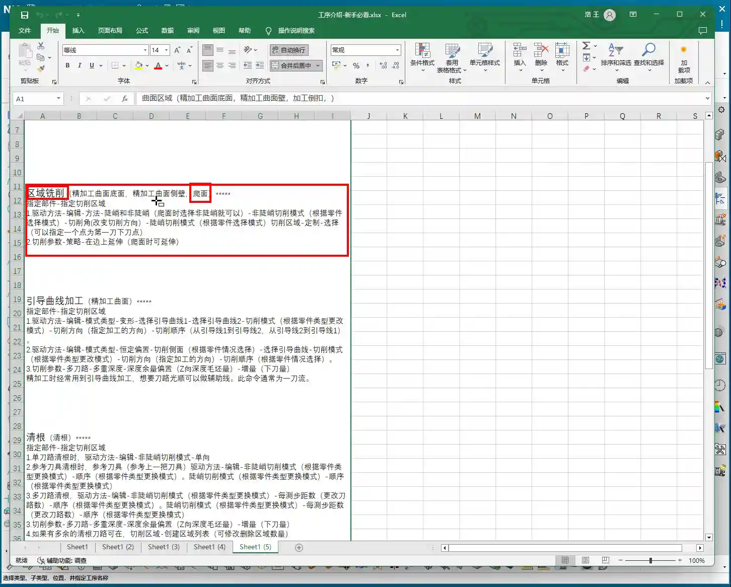
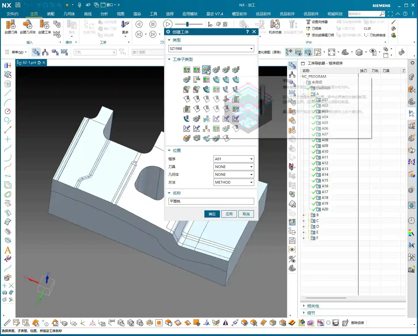
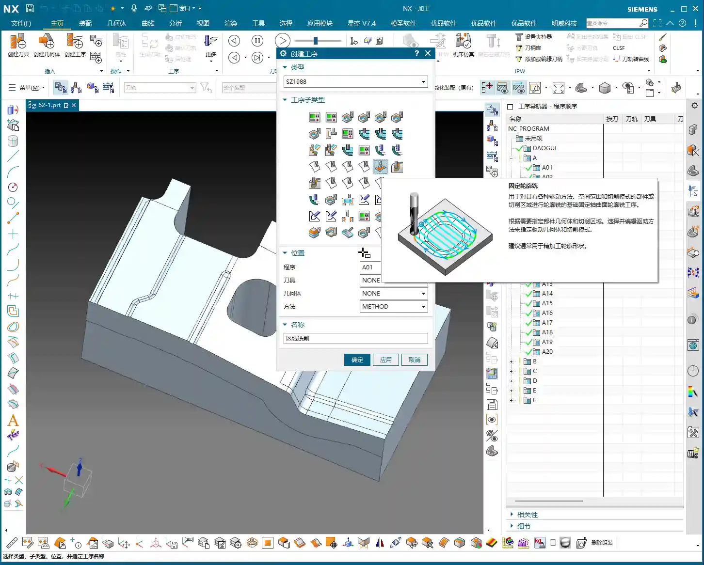
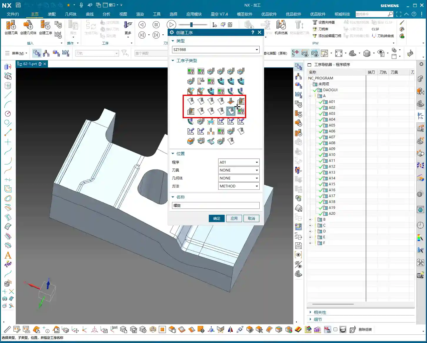
    Generally, in NX, many machining operations require you to explicitly specify the part to be machined. However, in “Fixed Contour Milling,” especially when dealing with drive methods like Boundary Flow Curves, Surface Area, Specify Cut Area, and today’s “Curve Point,” you might notice a strange phenomenon: sometimes, the program will run even if you don’t select “Specify Part”!

    Why is that? Because it allows you to select within the “Drive Method.” But this doesn’t mean you can just skip it whenever you want. Many engineers stumble here, thinking it’s fine not to select it, only to get stuck later when using Offset or Multiple Passes, with the program either overcutting or throwing an error. So, while it gives you this “flexibility,” you need to know when to use it and when it’s a critical error point! It’s like driving: you can coast in neutral, but would you dare to do that all the way down a steep hill? You’d certainly engage a gear and use the brakes – safety first!

    Chapter Two: The Art of Curve Selection and Toolpath Direction

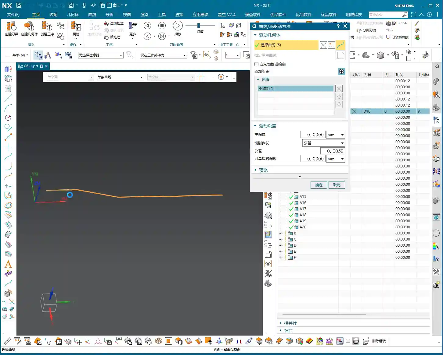
    Let’s start with the most basic: curve selection. In Fixed Contour Milling, if you don’t specify a part, then you must diligently select your machining curves within the “Edit” options.

    Curve Selection Techniques and Machining Direction

    Once you select a curve, you’ll see a green arrow. This isn’t just for show; it dictates your cutting direction. Double-click this arrow, and the direction will reverse. This is crucial in actual machining, as it determines climb milling or conventional milling, which impacts cutting forces, chip evacuation, and surface finish! Don’t just rely on software simulations. How the sparks fly, whether there’s chatter or chip welding during cutting – that’s the real feedback. Your eyes and ears are far more reliable than software animations!

    The program will follow the trajectory of your selected curve. If the curve is 3D, it will follow 3D; if it’s 2D (planar), it will follow 2D. Simply put, it can generate toolpaths for both 3D and 2D, completely following the lines you’ve selected. As long as the lines are chosen correctly and the direction is clear, program generation takes mere minutes. Efficiency lies in these small details.

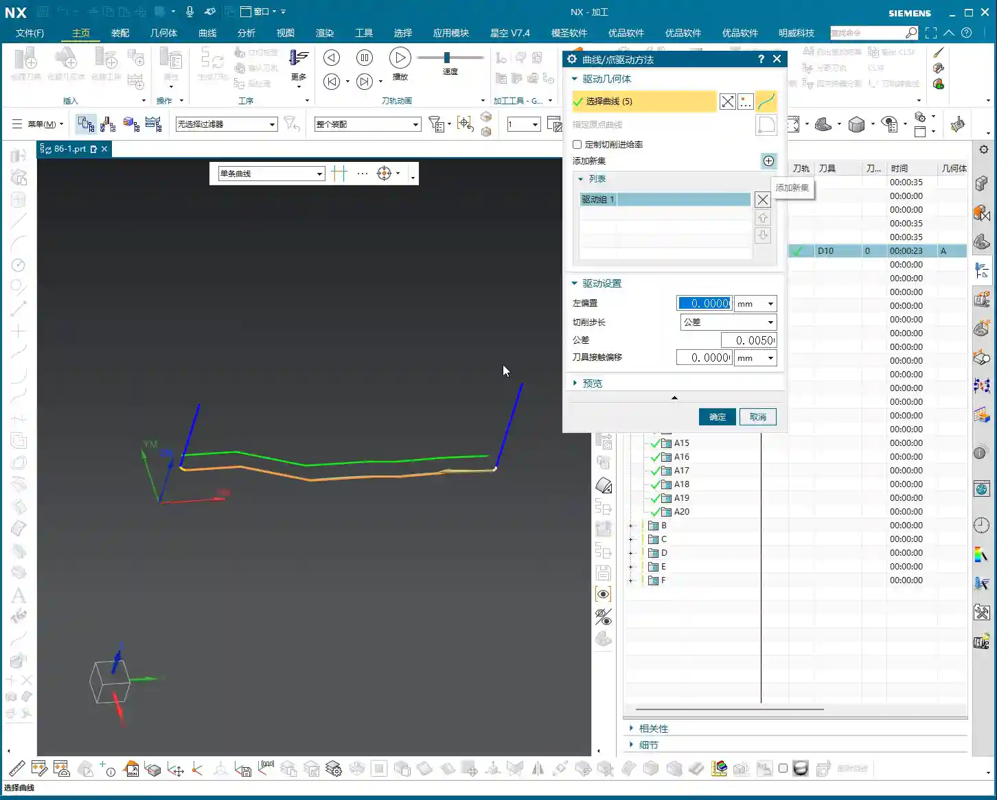
    “Add Feed”: The Connector for Multi-Curve Machining

    When we need to machine multiple discontinuous curves, NX provides an “Add Feed” function. Click this, and it will automatically connect these curves for you, allowing the tool to transition smoothly from one curve to another, avoiding unnecessary rapid retracts and air moves. But remember, even with this feature, you still need to plan your cutting order carefully to minimize idle travel – that’s what truly makes it efficient! Good programming saves money; every unnecessary rapid retract wastes valuable time.

    Chapter Three: The Core Secret – Why Are Offset and Multiple Passes Dependent on Specifying a Part?

    This is the absolute core of what we’re discussing today! As we just explained, sometimes a toolpath can be generated without selecting “Specify Part.” But this situation comes with a major caveat!

    The Root Cause of Offset Failure: No “Reference Boundary”

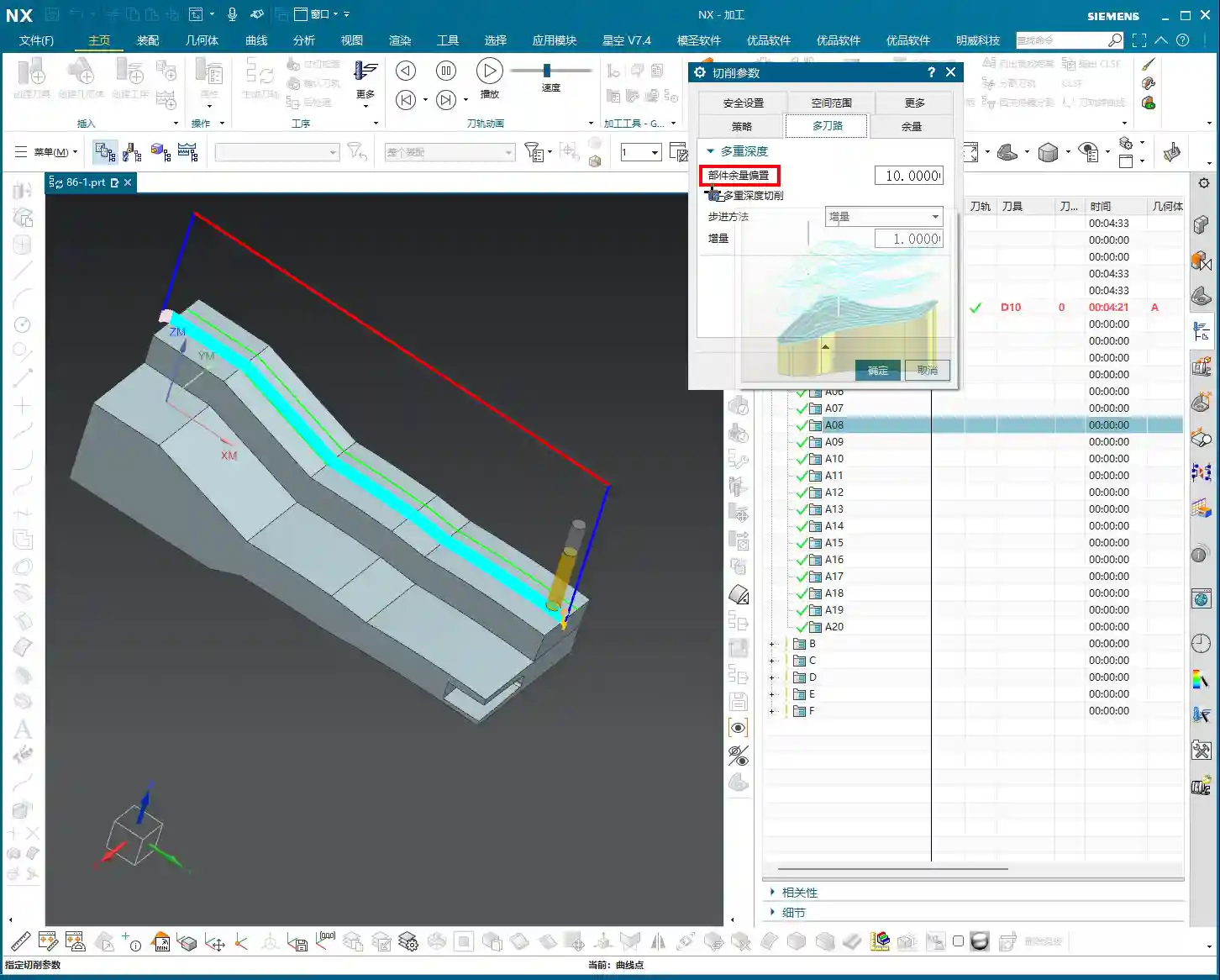
    Now, try to apply an Offset to your toolpath, say, by 10 mm. You’ll find that the program might directly throw an error, or even if it generates a toolpath, a simulation will reveal that the tool has moved into the part, resulting in a direct overcut! Why does this happen?

    Because you haven’t specified the part, the software doesn’t know where your “part boundary” is! When you try to perform an offset, it doesn’t know whether to offset “inward” or “outward,” nor does it know if the offset will collide with the part. It’s like a person who has lost their reference point, blindly offsetting, and the result is the tool tip directly plunging into the part’s interior. This is extremely dangerous; putting it on the machine will scrap the material! Don’t just look at the tool center path being outside; the tool tip could have already penetrated the part.

    Multiple Passes (Multi-Layer Cutting) Also Rely on the Part

    By the same logic, if you want to use the “Multiple Passes” function for multi-layer cutting, you must also specify the part. Without a part as a reference, the software cannot determine the safe boundary for each cutting layer, which will also lead to overcutting or the inability to generate correct toolpaths. This is like trying to navigate stairs in a dark room; without light, you have no idea if there’s a step underfoot, and you’re bound to fall!

    To summarize: When you need to use functions like “Offset” or “Multiple Passes,” you absolutely must diligently “Specify Part”! Otherwise, the tool will be unable to correctly determine safe areas and cutting boundaries, inevitably leading to serious machining accidents. Generally, selecting just the surface you intend to machine as the part is sufficient; there’s no need to select the entire component. Efficiency is important, but safety is paramount.

    Tolerance and Cutting Compensation: The Cornerstone of Precision

    In the “Cutting Parameters” settings, we typically choose “Tolerance” rather than “Number of Passes.” This tolerance controls your toolpath precision. I usually recommend setting it to 0.005 mm (which is 5 microns). Don’t underestimate these few microns; they directly impact your part’s surface finish and dimensional accuracy. Especially for high-precision molds or aerospace components, this is absolutely critical! A smaller tolerance results in a more detailed toolpath, but also a larger program size and longer machining time, so you must weigh this against actual requirements. The tolerance settings for common aluminum parts and titanium alloys will certainly differ; it depends on the specific material you’re machining and the required precision.

    As for “Tool Contact Offset” and similar settings, we’ll delve into those later when we discuss more complex Surface Milling, as there are many more nuances there.

    Summary: Pitfall Avoidance Guide

    • Master the “Specify Part” function: In Fixed Contour Milling’s Curve Point drive method, if you’re just making a simple pass along a curve, you *can* omit specifying the part. However, if you want to use functions like Offset, Multiple Passes, or Part Stock, you absolutely *must* specify the part! Otherwise, the tool will overcut, the program will error out, or even result in a machine crash. This is an unbendable rule!
    • Curve direction is critical: Double-clicking the curve arrow reverses the direction, which affects your climb milling/conventional milling strategy. This has a significant impact on machining quality and tool life, so always check it carefully. If the direction is wrong, the machined surface will look terrible, or the tool might even break.
    • Tolerance settings must be precise: It’s recommended to change the “Cutting Parameters” to “Tolerance,” typically set to 0.005mm. This is fundamental for ensuring machining accuracy, but also consider machining efficiency. A tolerance that’s too loose will compromise accuracy; one that’s too tight will lead to excessively long machining times. You need to find a balance.
    • Remember offset direction: Keep in mind, when the arrow points towards the inside of the part, a left offset corresponds to a positive value (e.g., 10mm), and a right offset corresponds to a negative value (e.g., -10mm). Getting this detail wrong will reverse the offset direction and could lead to a direct tool collision. Don’t be careless.
    • Practical experience trumps theory: Don’t just stare at the blue toolpaths in the software. Pay close attention to the sparks, sounds, and vibrations during actual cutting – that’s the machine “talking” to you. These “un-textbook” experiences are the stepping stones to truly becoming a master machinist! Get hands-on, think critically, and you’ll integrate knowledge effectively.

    👤 About the Author:
    The author is a veteran CNC machining professional with 15 years of industry experience, specializing in UG NX programming. This article is an original work representing personal practical insights.

    ⚠️ Copyright Notice: Unauthorized reproduction or distribution without prior communication is strictly prohibited.

  • Siemens NX Fixed Contour Milling: In-depth Analysis – Master Wang’s 15 Years of Practical Experience

    📝 Key Takeaways: ** Fixed Contour Milling: The Core of Finishing

    Master Wang Explains: What is Fixed Contour Milling?

    Alright, listen close, lads! Today, Master Wang is going to talk to you about a crucial feature in Siemens NX (UG) – Fixed Contour Milling. Don’t let its unassuming name fool you; this is our go-to method, our bread and butter, for achieving high-precision parts and finishing complex surfaces!

    You might have noticed several machining operations in the Siemens NX interface that look similar, with ‘Fixed Contour’ in their names. Today, Master Wang is going to clear things up for you: Fixed Contour Milling isn’t a single, specific machining method; it’s a general term, a whole family of operations! Just like when we discussed Face Milling and Cavity Milling, it has many sub-categories. It differs from typical operations like Face Milling, which handles planar surfaces, and Cavity Milling, which focuses on pocketing. But Fixed Contour Milling is specifically designed for surface features, especially complex, irregular freeform surfaces. If you need precision and surface finish, this is the one! Got it?

    The Core Function of Fixed Contour Milling: A Finishing Powerhouse

    Since it’s called “Fixed Contour Milling,” its primary strength is Finishing Pass. Mark my words, it’s almost never used for Roughing. The efficiency is too low; that’s simply not its job! Its forte is the final smoothing of surfaces, top faces, and sidewalls, ensuring the part’s dimensional accuracy and surface finish meet specifications. Think about it: aerospace blades, automotive mold cavities – how could they be produced without this technique? We typically pair it with a ball-nose end mill, meticulously ‘sculpting’ the surface, striving for that ±0.005mm (approx. 0.0002 inch) or even higher precision.

    The ‘Family Members’ of Fixed Contour Milling in Siemens NX (UG)

    Since it’s a large family, there are naturally different “members” for different tasks. While they all fall under “Fixed Contour Milling,” each branch excels in specific areas. The commands you see in Siemens NX under this category are essentially its “branches.” Today, we’ll start with an overview, and later, Master Wang will break them down one by one and teach you how to use them. The ones you see here are branches of Fixed Contour Milling; though their names may vary, at their core, they are all designed for high-precision Surface Milling:

    • Fixed Contour – Curve/Point: This is the most straightforward; it generates toolpaths along the curves or points you specify. Ideal for situations requiring precise trajectory control.
    • Fixed Contour – Boundary: Primarily used to restrict the machining area. Sometimes, when we only need to machine a specific section of a surface, this allows us to confine the tool’s movement precisely.
    • Fixed Contour – Flow Line: This is excellent for managing surface texture and direction. It allows the toolpath to follow the natural contours of the surface, resulting in exceptional surface quality and often eliminating the need for subsequent polishing or grinding.
    • Fixed Contour – Surface Area: One of the most commonly used. You directly select the surface or surface area to be machined, and Siemens NX will automatically generate the toolpath based on the geometry. This is the most fundamental and versatile Finishing Pass method.
    • Fixed Contour – Single Pass Corner Cleanup: A sharp tool for tackling small radii and tight corners. Using a smaller tool for a single pass to clear areas that larger tools couldn’t reach.
    • Fixed Contour – Multi Pass Corner Cleanup: More refined than a single pass, typically used for more complex or deeper material removal in residual areas, ensuring every corner is pristine.
    • Fixed Contour – Reference Tool Corner Cleanup: This intelligent method tracks which tools you’ve used previously and where residual material was left, then automatically plans the cleanup paths for smaller tools based on this information.
    • Fixed Contour – Helical Machining: While used less frequently, in specific cases like concentric cylindrical surfaces or structures with helical features, employing a helical approach for Depth of Cut (DOC) can result in more stable machining and a more uniform surface.

    These are all Finishing Pass operations. Siemens NX also features Variable Contour Milling, which is used for 5-axis machining. It’s very similar to the Fixed Contour Milling family members, but it adds one or two rotational axes of motion freedom. Today, we’re focusing on Fixed Contour Milling, which is primarily for 3-axis or 3+2-axis applications.

    Veteran’s Practical Wisdom: Siemens NX Operations and Optimization

    Theory alone won’t get you anywhere. No matter how pretty the Siemens NX simulation looks, the real test is the actual outcome on the machine. Master Wang has a few hard-earned practical tips here, so you boys better take notes:

    • Toolpath Optimization: Don’t always rely on the software to do all the thinking; put effort into adjusting feed rates, Depth of Cut (DOC), and Stepover. Especially in areas with high curvature changes, use a smaller Stepover and a slower feed rate, and you’ll get a smoother surface. Optimize toolpaths to be as continuous, smooth, and minimize tool lifts as much as possible. More air cuts mean longer cycle times and higher costs.
    • Material Properties: Machining different materials requires adjusting parameters accordingly. Aluminum can handle fast feed rates and deep cuts, but tough materials like titanium alloys and high-temperature nickel-based alloys require small Stepdowns, slow feed rates, and careful attention to cooling. These materials are prone to heavy cutting forces, leading to rapid tool wear, or even worse, tool chipping and scrapped parts.
    • Clamping Strategy: Finishing passes are most susceptible to deformation. For complex surface parts, Clamping must be secure but not overtightened, to avoid stress-induced deformation from the fixture. Sometimes, it’s necessary to design custom support fixtures or employ a strategy of multiple clamping setups with progressive machining.
    • Tool Selection and Grinding: For ball-nose end mills used in Finishing Pass, the tool radius and flute length are crucial. For some special radii, you might not find suitable tools on the market, so grinding custom tools ourselves is a common occurrence. A skilled tool grinder directly influences machining quality and efficiency.
    • Error Compensation: Machines accumulate accuracy errors over time, or due to environmental temperature changes. The Siemens NX program output is a theoretical value; during actual machining, you must learn to observe sparks, listen to cutting sounds, and measure actual dimensions. If you encounter accuracy issues of ±0.005mm (approx. 0.0002 inch), don’t panic. You can fine-tune by adjusting tool radius compensation (G41/G42), machine geometric error compensation, or modifying the stock allowance in the program. Don’t make impulsive changes; proceed incrementally.

    Summary: Pitfall Avoidance Guide

    Master Wang has a few final words of advice; these are lessons learned through hard-earned money and countless scrapped parts:

    1. Never use Fixed Contour Milling for Roughing! It’s meant for Finishing Pass work. Forcing it to tackle large stock amounts will be inefficient and likely lead to worn or burnt tools.
    2. Thoroughly understand the characteristics of each branch! Even though they’re all called ‘Fixed Contour Milling,’ each branch has its most suitable application scenario. Blindly choosing will only lead to wasted effort and suboptimal results.
    3. Don’t just trust software simulations; watch the cutting sparks! What looks perfect in the software might result in chatter or surface marring during actual machining. On-site observation and timely adjustments to feed rates and spindle speeds are paramount.
    4. Pay close attention to post-processing and machine characteristics! Especially for 5-axis simultaneous machining, modifications to the post-processor file are critical, as they directly impact toolpath execution. Every machine has its own ‘personality’; you need to understand it inside and out.
    5. For high-precision parts, cost-efficiency is always paramount. Before each machining operation, consider various factors—tools, process, fixturing—to achieve the highest precision with the lowest cost and shortest time.

    Fixed Contour Milling is a hardcore skill. Master it, and you’ll have solid confidence on the shop floor. In upcoming lessons, Master Wang will guide you through each of these branches until you’ve thoroughly mastered them. Then you’ll really get it.

    👤 About the Author:
    The author is a veteran CNC machining professional with 15 years of industry experience, specializing in UG NX programming. This article is an original work representing personal practical insights.

    ⚠️ Copyright Notice: Unauthorized reproduction or distribution without prior communication is strictly prohibited.

  • UG NX 1980 Geometric View in Machining: Practical Guide to Coordinate System Setup and Pitfalls

    📝 Key Takeaways: Master Wang provides a hands-on guide to the core of Geometric View in UG NX machining: WCS and MCS positioning and correlation. Master practical skills for creating geometric objects, correctly setting reference coordinate systems, and safety planes to avoid common machining errors and ensure efficient and safe production.

    Introduction: The Core of Coordinate Systems in Machining

    Hello everyone, I’m Master Wang. Previously, we discussed creating tools in the Program View and Machine View. Those were the basics, quite straightforward. Today, let’s talk about something more critical – the Machining Coordinate System. Listen up, whether it’s 3-axis or 5-axis machining, workpiece positioning relies on it. Especially in UG (NX), it’s the “foundation” of your machining.

    Distinguishing WCS from MCS

    When modeling, we all know about WCS (Work Coordinate System), which is used for design. But when we get to the manufacturing module, the true core is MCS (Machine Coordinate System). Remember, MCS is the reference for our actual programming and machine execution.

    A part might have many operations, and each operation may target a different machining area. You can create countless MCSs as needed. For example, if you’re face milling this surface or machining that hole, an MCS can be set for each position.

    Step One: Positioning and Adjusting the WCS

    To establish a reliable MCS, you first need to position your WCS (Work Coordinate System) correctly. This is the first step, and it’s fundamental. You can place it at any location you find convenient for operation, such as a corner or a face of the workpiece. There are detailed tutorials in the modeling module. Here, we’ll just click it and confirm its initial position by double-clicking or using the middle mouse button.

    For instance, we place the WCS at the top-left corner of the workpiece, serving as our machining reference zero. This position must correspond to your actual clamping and tool offsetting setup.

    Step Two: Creating a Geometric Object

    In the UG (NX) interface, after accurately positioning the WCS, the next step is to click the “Create Geometric Object” option.

    Meaning and Function of Geometric Objects

    The essence of “Create Geometric Object” is to create a new geometric group object within the Geometric View of the Tool Path Navigator. This geometric group acts like a container for geometric data associated with a specific MCS, such as machining features, boundaries, etc.

    Typically, we use templates with pre-defined geometric objects, such as DB, 3-axis, or 5-axis templates. These pre-set geometries are convenient for quick access. When a template is loaded, it automatically switches to the pre-defined geometric object, like DB.

    Selecting Geometric Object Sub-Types

    Here, you’ll find sub-types like A, B, C, D, etc. Listen up, here’s a practical tip: It’s best to keep your geometric object sub-type consistent with your current program name. If your program is named “A,” then select “A” for your geometric object sub-type as well. This makes management clear and helps avoid errors.

    As for other options, like those dropdown menus with small triangles, don’t worry about them for now. We’ll go into detail when we discuss specific machining processes later.

    Crucial Setting: Modifying the Reference Coordinate System

    After you’ve created and confirmed the geometric object, you’ll enter the MCS dialog box. There are many options here, most of which you don’t need to touch. However, one place you absolutely must change is the “Reference Coordinate System.”

    Discarding the Absolute Coordinate System, Embracing the Work Coordinate System

    By default, the reference coordinate system might be the “Absolute Coordinate System.” This absolute coordinate system is the software’s own center and has no relation to our actual workpiece positioning. Therefore, we must change it to the “Work Coordinate System,” which is the WCS we set in the first step.

    Remember: WCS is the coordinate system you manually place; it is where you put it. MCS, on the other hand, is what you truly need for programming, and it must reference your WCS. When these two overlap, your program will execute accurately.

    Safety Settings: Plane Selection

    In the MCS parameter settings, another important point is the “Automatic Plane” within “Safety Settings.”

    Plane vs. Surface: A Mistake You Cannot Afford to Make

    Typically, especially in 3-axis machining, we need to manually select “Automatic Plane” as “Plane.” Click it, and then specify a plane as the safety plane. Never choose a surface! If you select a surface, your tool retract and engage movements will be chaotic, which could lead to chatter or even scrapping the workpiece! We must specify a plane as a reference for the safety height, for example, a plane on top of the workpiece.

    As for the numerical input that follows, like 100, that’s the height offset for your safety plane. This height is set based on your workpiece’s actual dimensions and safety requirements to ensure the tool safely retracts during non-cutting movements.

    Summary: Pitfall Guide

    • Coordinate System Positioning: WCS is the foundation of machining. Be sure to position it precisely according to your actual clamping setup. Don’t just rely on software simulations; look at the cutting sparks!
    • Geometric Object Naming: The geometric object sub-type should preferably be consistent with the program name for clear management and to avoid confusion.
    • Reference Coordinate System: The MCS reference coordinate system must be changed to “Work Coordinate System,” not “Absolute Coordinate System”! This is a common mistake for many beginners.
    • Safety Plane: In “Safety Settings,” always select “Plane,” never “Surface.” Specify a safety plane and provide a reasonable safety height. This directly relates to the safe operation of the machine; get it wrong, and you’ll be experiencing tool deflection!
    • Practicality First: UG (NX) has many parameters, but you don’t need to understand every single one. Grasp the core parameters, know how to use them, and use them correctly. For the rest, gain experience on the shop floor; practical experience is more important than textbooks.