📝 Key Takeaways: In this hands-on tutorial, Master Wang shares his expertise on tool selection, creation, and parameter configuration in Siemens NX 1980. Learn how to efficiently manage your tool library, set tool numbers, compensation numbers, and cutting lengths to avoid common programming errors and boost machining efficiency. Practical knowledge you can apply immediately!
Previous Review and Function Overview
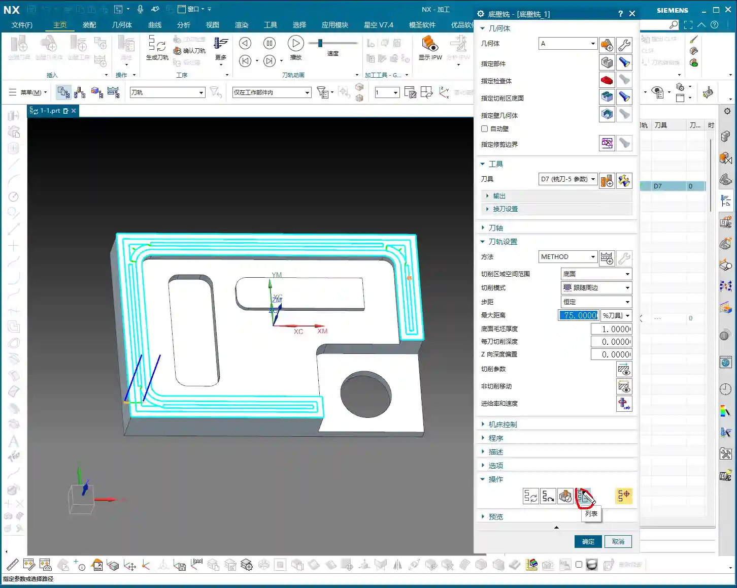
Hello everyone, I’m Master Wang. Let’s pick up where we left off. We’ve already covered all the functions in that first section. As for “Trim Boundary” and “Specify Boundary,” these aren’t used very often, so we’ll just briefly touch upon them for now and might revisit them later.
Listen up! Pay special attention to the “Specify Bottom Boundary” function. Frankly, I don’t particularly recommend using it, but since it’s in the software, we still need to know how to use it to avoid potential pitfalls later on.
Core: Tool Selection and Generation
Tool Selection
Look at this section, the “Tool” option. It’s straightforward: choose the tool you want to use. For example, if the default is a D16 (16 mm diameter) tool, we can switch to a D4.7 R0 tool (4.7 mm diameter, 0 corner radius).
Remember these three crucial steps:
1. Specify Blank
2. Specify Cut Area
3. Select Tool
As long as you get these three steps right, you generally won’t make major mistakes. Don’t just rely on software simulations; you need to observe the actual cutting sparks and results!
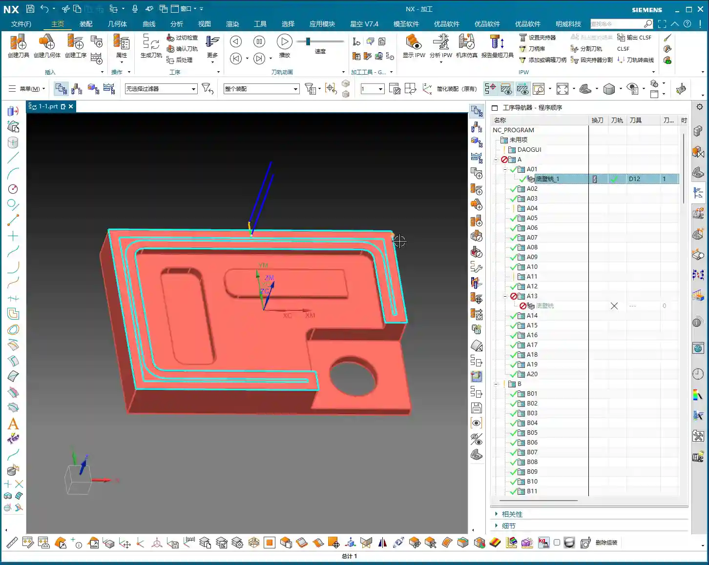
Importance of Program Generation
After selecting the tool and setting the parameters, the most important step is to click the “Generate” button. Once you click it, the program will generate the toolpath for you.
Let me give you an example. Say you change the tool from D4.7 to D5.8. After making the change, the tool in your toolpath might still be using the D4.7 parameters internally. You must click “Generate” for your changes to be truly applied.
This “Generate” step is the most critical one every time you modify parameters. You can either change all parameters at once and then generate, or change one step and generate. Either way is fine. But any change requires generation!
We’ll talk about “Replay,” “Verify,” and “List” later. But the importance of “Generate” outweighs them all.
Methods for Tool Creation
Method One: Copy and Paste
If the current tool library doesn’t have the tool you need, like a D17 tool, don’t rush to search for it. We can “Copy” an existing tool and then “Paste” it.
Next, double-click the pasted tool, rename it to “D17,” and confirm. Just like that, a new D17 tool appears in your tool library.
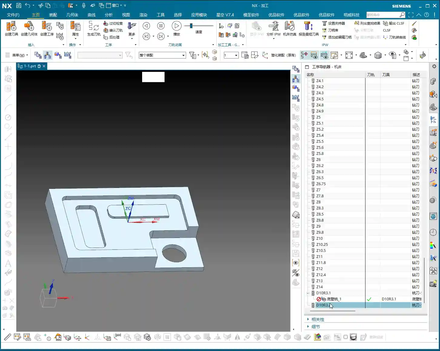
Method Two: New Tool Creation
Besides copying and pasting, we can also directly click “New” to create a tool. For example, let’s create a D10 R3.1 tool.
Pay attention: If you try to create a D10 R3 tool, and your tool library already has one with that name, you won’t be able to create another tool with the same name. So, it’s best to use a distinct name, such as adding a prefix like “E10 R3.1” to avoid conflicts.
Simply enter the name and corresponding parameters, such as diameter D10 and corner radius R3.1, then confirm. The new tool is now created. This is effectively the same as copying, pasting, and renaming. Both methods work, use whichever you find more convenient.
Method Three: Create within an Operation
When creating an operation, there will also be a “Create Tool” option. This function is identical to the “New Tool” option mentioned earlier. You only need to learn one tool creation method; there’s no need to master every single one.
So, in summary, you can create tools either externally via “New” or “Copy and Paste,” or directly within an operation. All methods are viable.
Modifying Tool Parameters and Output Settings
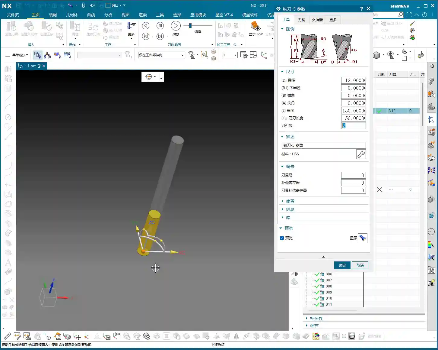
Editing Tool Parameters
Click “Edit Display” to modify tool parameters. However, there’s a pitfall here: if you directly change the name or diameter, for example, changing D10 R1 to D11 R1, the tool’s name in the list will still show D10 R1, but its internal parameters will have changed. This is highly confusing, and I do not recommend doing this!
What I suggest changing here are only the physical dimensions of the tool, such as “Tool Length” and “Cutting Length.” For instance, changing the tool length to 150mm and the cutting length to 50mm is perfectly fine. As for the “Number of Flutes,” you can change this, but usually, it doesn’t have a significant impact if left as default; the software’s default is often sufficient.
So, after modifying these physical dimensions, the tool’s name in the list will remain the original D12, but its actual dimensions will have changed according to your input.
Output Settings and Post-Processing
Next, let’s look at the “Output” options. Here we have “Tool Number,” “Compensation,” and “Length Compensation.” By default, they are all set to 0.
What do these mean? Simply put, they relate to the G-code generated during post-processing. For example, your G-code might contain M6 T1 (tool change to tool 1) or G43 H1 (length compensation 1).
Your “Tool Number” corresponds to that T-number. If you set it to 1 here, then in the post-processed program, this tool number will be T1. If your company doesn’t have strict requirements, or if your workshop, like ours, uses non-standardized tools where operators manually perform tool offsetting and input compensation, then setting this to 0 is also acceptable; the operator will fill it in manually.
However, if you need the program to automatically output T1 H1, then set all three parameters (Tool Number, Compensation, Length Compensation) to 1, then “Generate.”
Listen up! Changing these parameters here won’t show any visual change in the toolpath within the software. Where do you see the effect? Only when you post-process the G-code! For example, if you select post-processing and then view the generated NC file, you’ll find codes like M6 T1 or G43 H1 inside.
Summary: Pitfall Guide
- Always “Generate”: Any modification to tool parameters (diameter, length, compensation, etc.) must be followed by clicking “Generate” to take effect. Otherwise, your program will still be using the old parameters. This is the most common mistake, so remember it!
- Be Cautious with “Edit Display”: Do not use “Edit Display” to change the tool’s “name” or core identifying parameters like “diameter/corner radius.” This only alters internal parameters and not the displayed tool name in the list, which can lead to extreme confusion. For such changes, please use “Copy and Paste then Rename” or “New Tool Creation.”
- Understand Tool Number and Compensation: If your workshop’s tool management is flexible and operators manually touch off tools and input compensation, then you can set “Tool Number,” “Compensation,” and “Length Compensation” to 0 in the software. However, if you need the program to automatically output these, you should set the corresponding values. Remember, these changes are only reflected in the G-code after “Post-processing.”
- Master Multiple Creation Methods: Learn the two primary methods: “Copy and Paste” and “New Tool Creation.” They are essentially the same, so choose whichever you prefer.
Leave a Reply