📝 Key Takeaways: Join Master Wang as he dives deep into UG NX 1980 plane milling operations. From the overall concept to specific applications like roughing, corner cleanup, helical milling, and engraving, he’ll guide you through setting up coordinate systems, creating geometry, and highlighting common pitfalls to boost machining efficiency and precision.
Hello everyone, I’m Master Wang.
Listen up. Starting today, we’re going to dive deep into plane milling. This isn’t just a simple job; there are many subtleties involved, and it can be broken down into many sub-processes.
Plane Milling: A Big Family
See, I’ll open up the operation interface for you. We’ve already covered Floor and Wall Milling and its capabilities, so I won’t repeat those details. Today, we’re focusing on plane milling.
Although it’s all called plane milling, it’s actually a general term, like the ‘boss’ of the family. Under this boss, there are many ‘branches,’ each capable of handling specific tasks. There are quite a few branches, so let me list some common ones for you:
1. Roughing
The first one is Roughing. Normally, for roughing, we use a face mill (or sometimes a side-cutting end mill, but the side flute can also cut). This operation feels similar to dynamic milling. It can not only machine flats (face milling) but also side walls, and you can even use the side flutes for corner cleanup. It’s highly efficient.
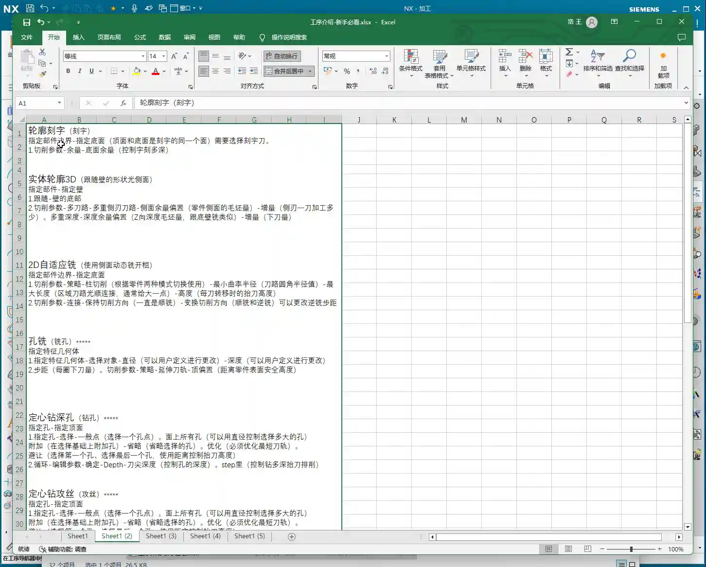
2. Plane Profile Milling
Plane milling also branches out into something called Plane Profile Milling. In fact, it’s also part of the plane milling family, but it’s specifically used for tasks such as:
- Roughing side walls
- Finishing side walls
- Adding chamfers
See, it can do quite a lot!
3. Contour Chamfering
Then there’s Contour Chamfering. You could also say that plane milling can perform chamfering because this operation is derived from plane milling. These two terms are essentially linked together.
4. Helical Milling
Helical Milling is also a type of plane milling. In specific deep pocket or hole machining, helical entry can effectively avoid center cutting, reduce tool wear, and improve machining stability.
5. Engraving
You heard that right, plane milling can even be used for engraving! While this function isn’t commonly used, it can be extremely useful in critical situations. There’s also 2D Dynamic Milling, which is also considered a branch of plane milling.
So, does plane milling seem less straightforward now? Suddenly, there are several operations, maybe five or six. They are all collectively called plane milling, but in my opinion, Master Wang’s, plane milling is mainly used for roughing, or simply plane profile milling, and also chamfering. Understanding these is enough.
UG NX 1980 Hands-On Operation: Plane Milling Setup
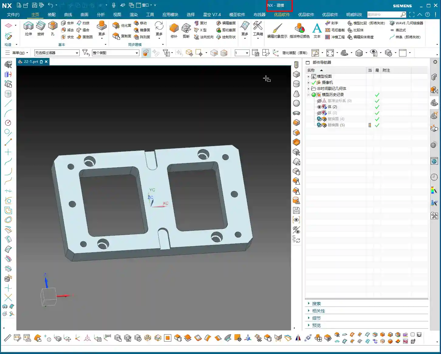
Let’s get started on how to use plane milling. First, open this part file. It’s in the “22-1” file, and this lesson is, of course, part of Episode 22. After opening the file, if your page doesn’t match mine, don’t worry. Click on “Delete Assembly”.
Delete Assembly: Cleaning the Work Environment
What does “Delete Assembly” mean? It means clearing all the programs, tools, methods, and geometry data you previously created in this file. It effectively deletes all four major categories of data, allowing you to start fresh. It will warn you that data cannot be recovered, but for our learning purposes, just click “Continue.” It’s my old program anyway, and we don’t need it for this lesson.
After deleting, the page will switch to the familiar modeling interface. If you click “Cancel” at this point, it will return to the modeling page. We usually click “OK,” but we’ll switch back again shortly.
On this modeling page, don’t worry about anything; it’s just a basic environment page. Just press the M key on your keyboard, and it will take us to the modeling page. Everything on the modeling page has been thoroughly explained in the modeling course, so I won’t waste time on it here.
Let’s directly switch from Modeling to the Manufacturing module. Click “Manufacturing.” See this dialog box? This is the one that popped up when we clicked “Cancel” earlier. Let’s click “Manufacturing” again.
Now we are in the manufacturing environment, which I’ve discussed when we first started programming. We won’t change this position; just select the third option.
Creating Geometry (Work Coordinate System)
The assembly to create is simply to insert a template. As mentioned before, this template is one I created myself. We can just use the default first one. Click “OK.”
This page should be very familiar now, right? ABCDEF and so on. All the tools are there, but the geometry hasn’t been created yet. Let’s create the geometry now.
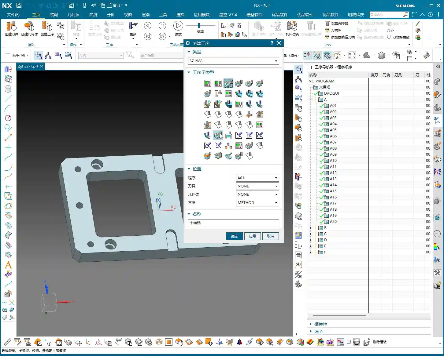
First, select Plane Milling, but since the geometry isn’t set up, the first step is to create geometry. Geometry refers to our WCS (Work Coordinate System). How to place this coordinate system for WCS orientation was also covered in the modeling course. Just click “OK.”
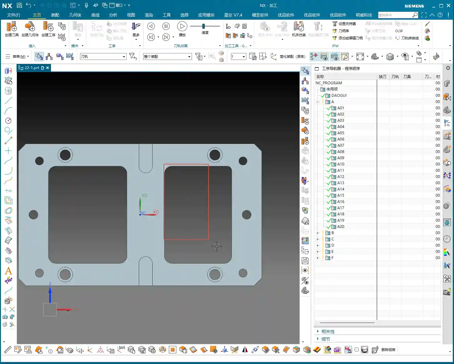
Then, dynamically drag the WCS to ensure it’s perfectly centered on the part. Is it centered? This needs careful checking. It might not look centered from the shape, but if you check with “Point Information,” you’ll find it is indeed centered. It’s just that the two slots might be slightly different in size, but the coordinate values are the same. Remember, every time you place a coordinate system, you must use “Point Information” to double-check its accuracy. This is a rule!
We’ll directly click “Create Geometry,” select A. All these settings remain unchanged. Geometry is always G1. This has been said many times before, so I won’t elaborate further. Just click “OK.”
Next, set up the Machine Coordinate System (MCS) and Work Coordinate System (WCS). Just enter 100, then OK.
Alright, our geometry (A, A-1) has been created. We’ll use it later. Click “OK.”
Right-click, Insert Operation, and select Plane Milling. For geometry, select A. Click “OK.”
So far, we have opened the Plane Milling operation. Next, we will go through all the parameters inside, one by one, from scratch. Although many parameters are the same as in Floor and Wall Milling, I won’t repeat the common ones. I’ll only cover what’s different. Because in programming, regardless of the command, many elements are universal, such as geometry, tools, tool axis, cutting parameters, feed rates, coordinate systems, and so on – these are all the same.
Summary: Pitfall Guide
- Differentiate Concepts: Plane milling is a broad category, with roughing, profile milling, chamfering, helical milling, and engraving each having their own focus. Choose the appropriate sub-operation based on actual machining needs.
- Clear Environment: Before starting a new project, always use the “Delete Assembly” function to ensure a clean work environment and prevent interference from old data. This isn’t about saving time; it’s about avoiding major problems later.
- Coordinate System Inspection: After placing the WCS (Work Coordinate System) each time, you must use the “Point Information” function to carefully check if the coordinate position is accurate, especially whether the part center is aligned. Don’t just rely on visual inspection; human eyes can be unreliable, data is king.
- Leverage Templates: Proficiently using and managing your machining templates can greatly improve programming efficiency and reduce repetitive setup.
- Parameter Reuse: In different machining operations, most parameters such as geometry, tools, and tool axis are common. Mastering the setup of these general parameters will allow you to apply your knowledge broadly and quickly pick up new operations.
Leave a Reply