📝 Key Takeaways: Master Wang reveals the core techniques of Siemens NX 1980 floor-wall milling. Learn practical parameter settings and anti-pitfall tips for roughing and finishing, boosting your machining efficiency.
Hello everyone, I’m Master Wang!
In this lesson, I’ll walk you through the ins and outs of floor-wall milling. We’ll cover what this feature can actually do in practical machining, where it’s used, and how to properly set those intricate parameters.
I. Floor-Wall Milling Basic Operations and Face Milling Roughing
Listen up! First step, let’s select the floor-wall milling operation.
1.1 Selecting Floor-Wall Milling and Specifying the Cutting Face
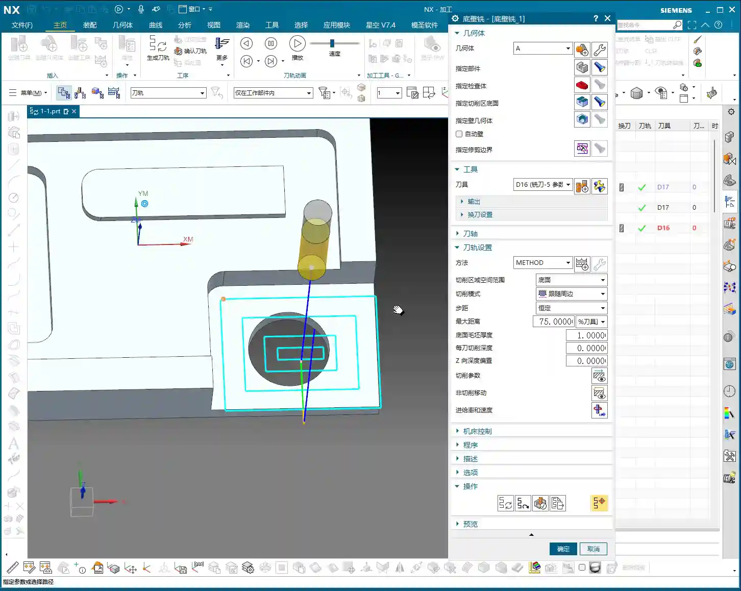
Once we’ve selected floor-wall milling, we’ll choose the part to be machined. By now, I believe you all understand this from previous lessons. The key here is to specify the bottom surface of the cutting area. For example, let’s select this face, then click OK.
1.2 Face Milling Strategy and Toolpath Optimization
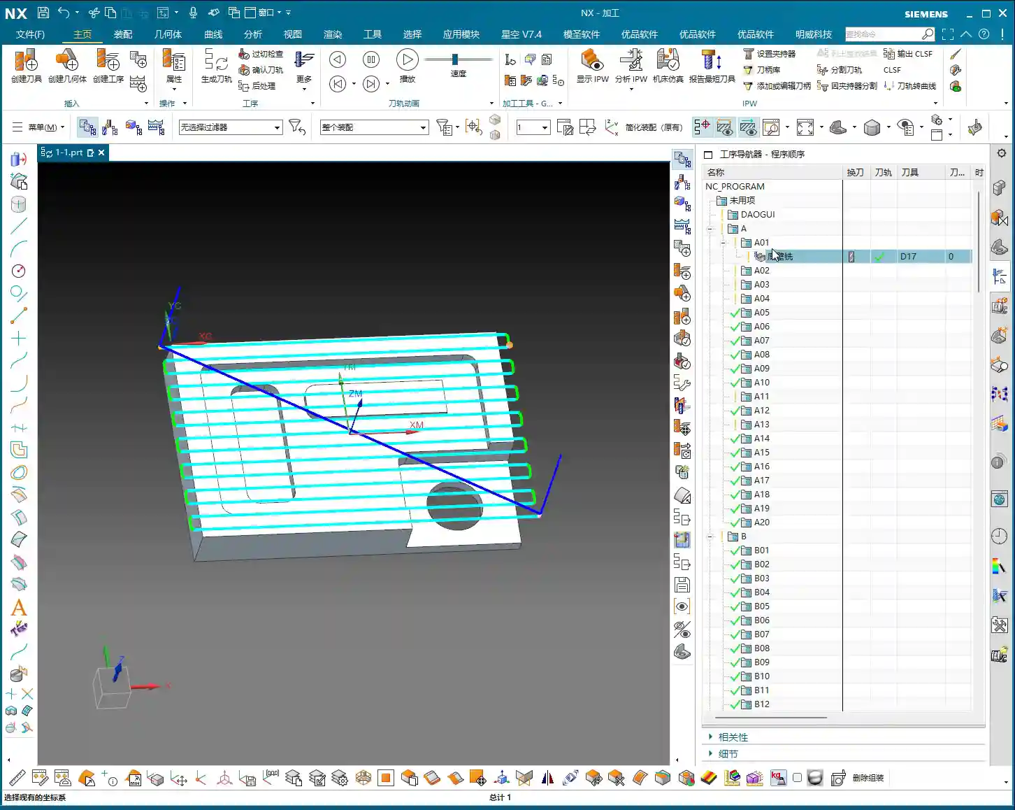
Now, our first step is to perform face milling. Pick a suitable tool, a 16mm or 17mm one, whatever you have on hand. For face milling, we usually use a zig-zag cutting pattern; that’s standard practice.
After generating the program, what? The toolpath ran outside the workpiece? Don’t fret, this is because our spatial range wasn’t set correctly. In the “Extend bottom face to” parameter, change “5” to “Contour“. After changing it, regenerate the program, and see, isn’t the toolpath much more orderly now, staying within the workpiece?
1.3 Toolpath Smoothing: Adding Corner Radius
To make the toolpath smoother and cutting more stable, we need to add something. Open the cutting parameters and find the corner radius setting. Give it a percentage, for example, 10% of the tool diameter, and then regenerate. See how the toolpath instantly became smoother? This is a little trick to reduce chatter/tool deflection and ensure surface quality.
II. Floor-Wall Milling Finishing Strategy
2.1 Copying Finishing Program and Adjusting Parameters
After roughing, there’s definitely still some material allowance on the workpiece surface. To get it smooth, we need to run a finishing pass. The easiest way is to copy the roughing program we just created and then paste it.
For instance, if we used tool A01 for roughing, for finishing, we’ll switch to tool A02, ensuring clear division of labor. Double-click to open this new program.
2.2 Single-Pass Finishing Settings
Finishing typically involves a single pass. So, set the “Depth of Cut (DOC) per pass” parameter directly to 0. That’s right, 0. This way, it will only take one pass. At the same time, in the cutting parameters, set the bottom face allowance also to 0. Keep other parameters unchanged, and just generate the program. This will ensure the toolpath precisely follows the bottom surface, guaranteeing dimensional accuracy.
III. Setting and Optimizing Roughing Areas
3.1 Roughing Specific Areas: Raw Material Thickness and Depth of Cut
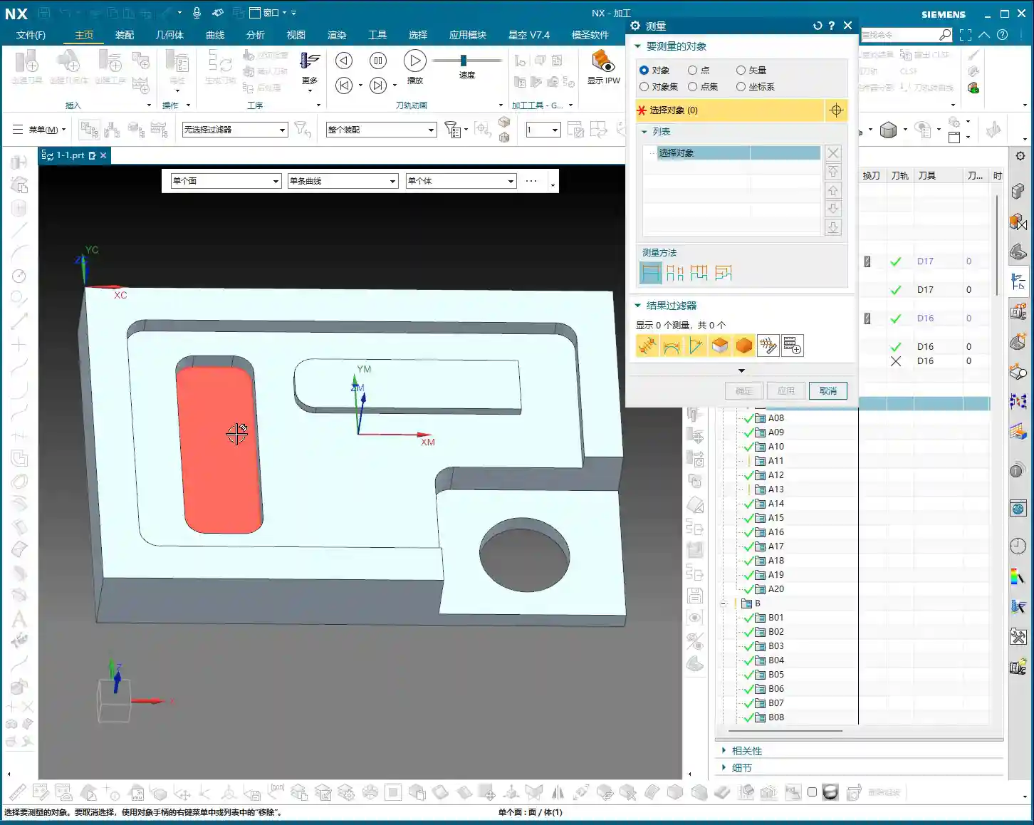
Besides face milling, we might also need to rough specific areas. For example, this region. First, specify the part and the cutting region, still selecting this bottom face.
By default, floor-wall milling leaves material allowance on both the side walls and the bottom face. However, if we need to rough an area with height, a single pass definitely won’t cut it. We need to measure the raw material height. Use the measurement tool to click an edge; for instance, this is 10mm.
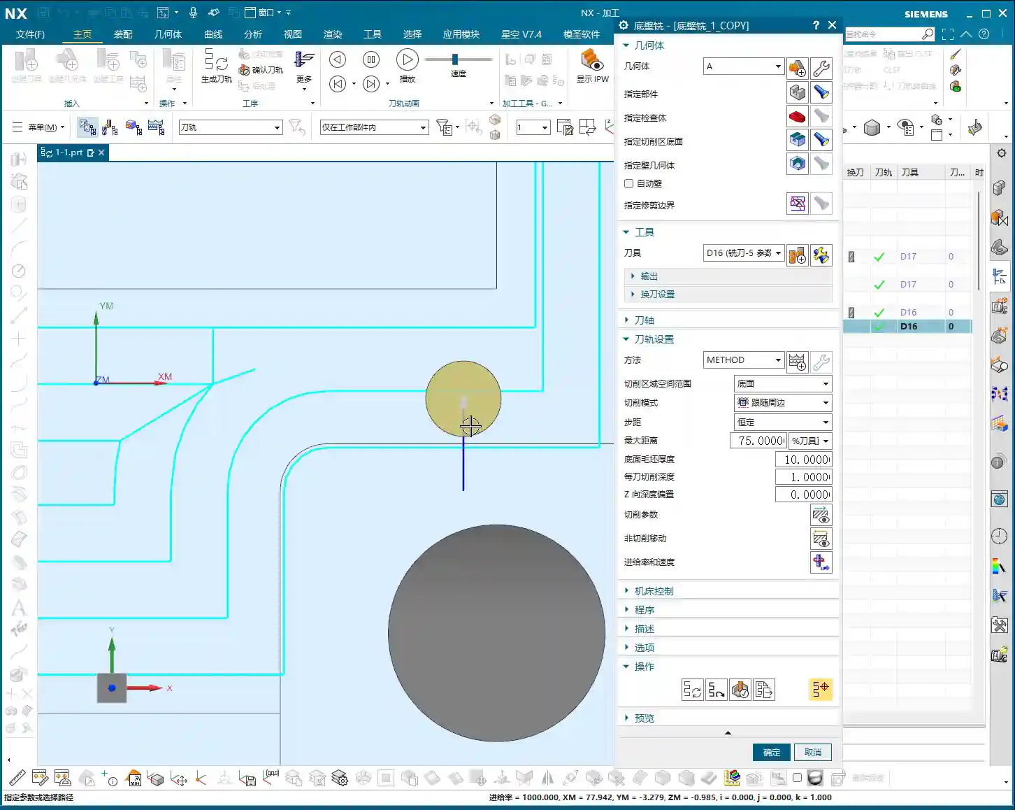
So, in the program, we’ll directly input 10mm for the raw material thickness, and then set the Depth of Cut (DOC) for each pass, for example, 1mm. Don’t touch any other parameters; just generate it directly. This will ensure all excess material is removed.
3.2 Adjusting Cutting Patterns: In-Region vs. Follow Periphery
Why does the tool lift so high in the middle and retract? This is actually related to the “in-region” cutting pattern. By default, it’s processed “in-region,” meaning the tool lifts to clear already machined areas. If we change it to “Follow Periphery,” the tool will follow the boundary, which might be more suitable for certain situations.
Remember, the choice of cutting pattern should always be based on the actual workpiece geometry and machining requirements. There’s no one-size-fits-all solution, only the one best suited for your current task.
IV. Simulation Verification and Troubleshooting
4.1 3D Dynamic Simulation: Real Cutting Process
Don’t just rely on software simulation; look at the cutting sparks! In Siemens NX, merely looking at the toolpath is just the first step. To truly verify if the program is correct, you need to use 3D dynamic simulation. Select the entire program folder, then click “Verify Toolpath“, and then click “3D Dynamic” to play. Before playing, remember to slow down the speed, otherwise, it’ll flash by and you won’t see anything clearly.
4.2 Identifying Issues: Unmachined Areas
Once the simulation runs, problems become apparent. See, some areas are milled, but others still have material allowance and haven’t been machined properly. This is like a blind spot; it looks fine on the surface, but there are actual unmachined areas. In such cases, we need further optimization.
V. Addressing Unmachined Areas: Tool Shape Root Parameter
5.1 Leveraging the “Tool Shape Root” Parameter
Don’t panic when you encounter unmachined areas. As we discussed before, if some areas are unreachable by the tool, adjustments are needed. In the cutting parameters, find the “B – Tool Shape Root” option. Check its box and regenerate. Now look, has the toolpath entered those previously unmachined areas? This is a trick to extend the machining range by utilizing the tool’s geometric characteristics.
5.2 Adjusting Inward/Outward Machining Direction
Sometimes, the direction of the toolpath is also crucial. For example, if you don’t like machining from outside to inside. You can change it in the parameters to “from inside to outside” or “from outside to inside.” These adjustments are all for achieving more stable cutting and smoother chip evacuation. How to choose specifically depends on the workpiece characteristics and your experience.
Summary: Pitfall Avoidance Guide
- Allowance Settings: Floor-wall milling defaults to leaving material allowance on both side walls and the bottom face. For roughing, remember to adjust as needed. For finishing, the allowance must be set to 0.
- Toolpath Extension: If the toolpath extends outside the workpiece during initial generation, check and adjust the spatial range parameter for “Extend bottom face to,” usually changing it to “Contour” will resolve this.
- Surface Quality: To improve surface finish and reduce chatter/tool deflection, don’t forget to add an appropriate corner radius in the cutting parameters.
- Raw Material Inspection: Before roughing specific areas, it is crucial to measure the raw material thickness accurately, input it, and set the Depth of Cut (DOC) per pass based on actual conditions.
- Simulation Verification: After generating the program, always perform a 3D dynamic simulation. Just looking at the toolpath isn’t reliable; simulation helps uncover potential unmachined areas or collision issues.
- Addressing Unmachined Areas: If unmachined areas are found, try adjusting the “B – Tool Shape Root” parameter to utilize tool characteristics and compensate for machining deficiencies.
- Cutting Direction: The machining direction (inward/outward) affects cutting forces and chip evacuation. Choose flexibly based on the workpiece and tool to achieve optimal machining results.
Leave a Reply