📝 Key Takeaways: Master Wang personally shares core insights on NX toolpath colors, stepover, and Depth of Cut (DOC). From air cuts to actual material removal, this guide deeply analyzes the practical significance of each step, teaching you how to precisely adjust parameters based on material and tooling, avoid common pitfalls, and significantly improve machining efficiency and part accuracy.
Hello everyone, this is Master Wang. Today, let’s pick up from our last discussion and talk about the secrets of “reading tool intent by color” in NX programming, along with the critical parameters of stepover and Depth of Cut (DOC). These are hardcore insights that directly impact your efficiency and scrap rate, so listen up!
I. Toolpath Colors: NX Tells You What the Tool is Doing
In NX software, toolpath colors aren’t just for show; they indicate the tool’s actions, corresponding to different G-code movements on the machine. You must understand these colors to truly grasp the tool’s intent. Software simulation alone isn’t enough; you need to combine it with observing actual cutting sparks!
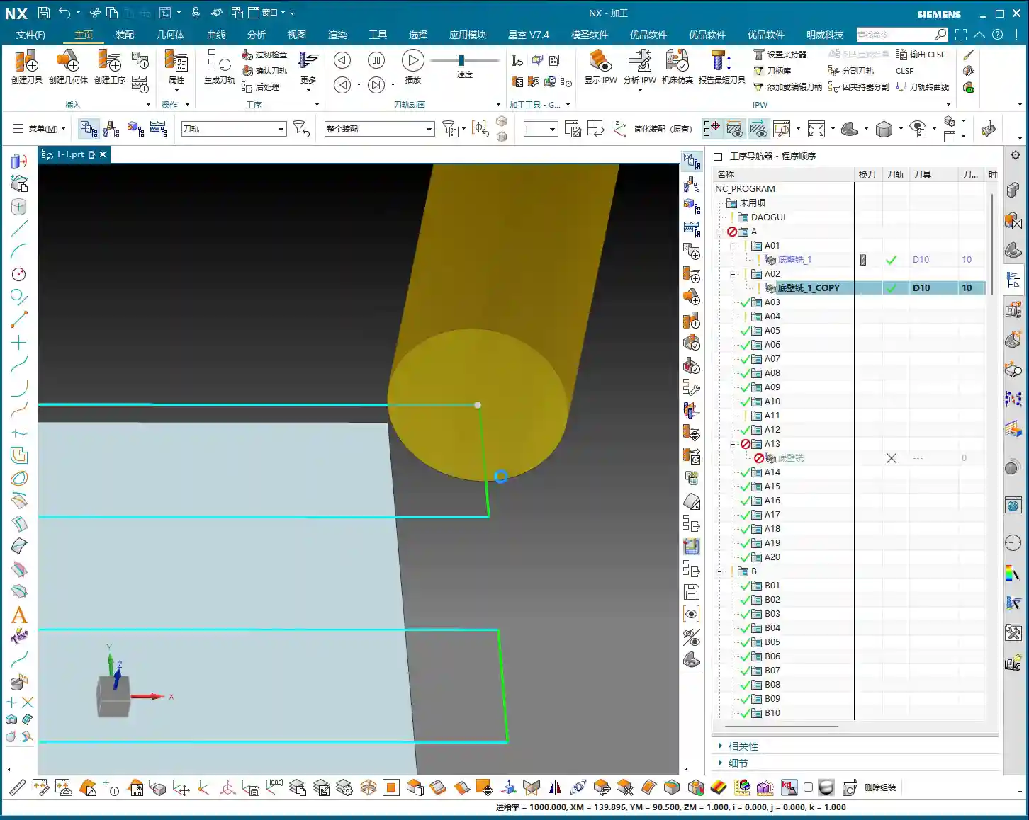
1. Blue: Rapid Moves – Go Fast!
See this blue toolpath? This represents Rapid Traverse, which corresponds to the machine’s G00 command. The tool moves at its fastest speed above the workpiece or in areas where it’s not in contact. This is an “air cut,” not removing material. So, in these areas, we aim for maximum speed – get there fast, don’t waste time!
Master Wang’s Tip: During rapid moves, always ensure the tool won’t collide with the workpiece or fixturing. Leave ample clearance; otherwise, a crash means the machine, tool, and workpiece are all scrapped!

2. Yellow: Approach – Stay Steady!
When the tool slowly approaches the workpiece from the air, preparing to start cutting, you’ll see a yellow toolpath. This is called the Approach/Entry, marking the start of tool-workpiece contact. The corresponding G-code is G01, but the feed rate will be relatively slow to ensure smooth engagement and prevent tool impact. Helical and ramp entries are common strategies to avoid sudden material engagement, reducing tool wear and workpiece vibration.

Master Wang’s Tip: The approach method and feed rate are crucial! Especially for deep cavities or hard materials, a poorly managed approach can lead to chipping or, worse, tool breakage. Slower and steadier is always better than rework. You can also set the approach to enter directly from outside the workpiece, which can reduce air cutting.
3. Light Blue: Actual Cut – Watch the Sparks!
The actual cutting begins! This is the light blue toolpath, representing Cutting, and it’s the core G01 action. At this point, the tool is genuinely removing material according to your programmed feed rate and spindle speed. What we often call “taking a bite” or “engaging the material” in the shop refers to this stage. This is the essence of your machining operation.
Master Wang’s Tip: Don’t just rely on software simulation; watch the cutting sparks! The color, shape of the sparks, and the cutting sound can all tell you about the tool’s condition. If the sparks are too yellow and coarse, the feed rate might be too slow, or the tool is dull. If they’re too bright and fine, the feed rate might be too fast, leading to excessive tool load. You need to observe carefully; that’s experience you won’t learn from books.
4. Green: Traverse Within Cut – Stay Engaged!
Within the same cutting level, when the tool moves from one area to another to continue cutting, but without lifting (or only lifting slightly, still remaining within the Depth of Cut (DOC)), you’ll see a green toolpath. This is called Traverse within cut. Like the light blue toolpath, it’s a cutting action, merely a lateral movement of the tool on or within the workpiece surface. Essentially, it’s also engaged in cutting.

Master Wang’s Tip: You can think of green and light blue as “brothers,” both actively working. Sometimes the software might even display them uniformly. The key is that the tool is still in a cutting state, or rather, it’s on its way to the next cutting point and hasn’t completely disengaged from the workpiece.

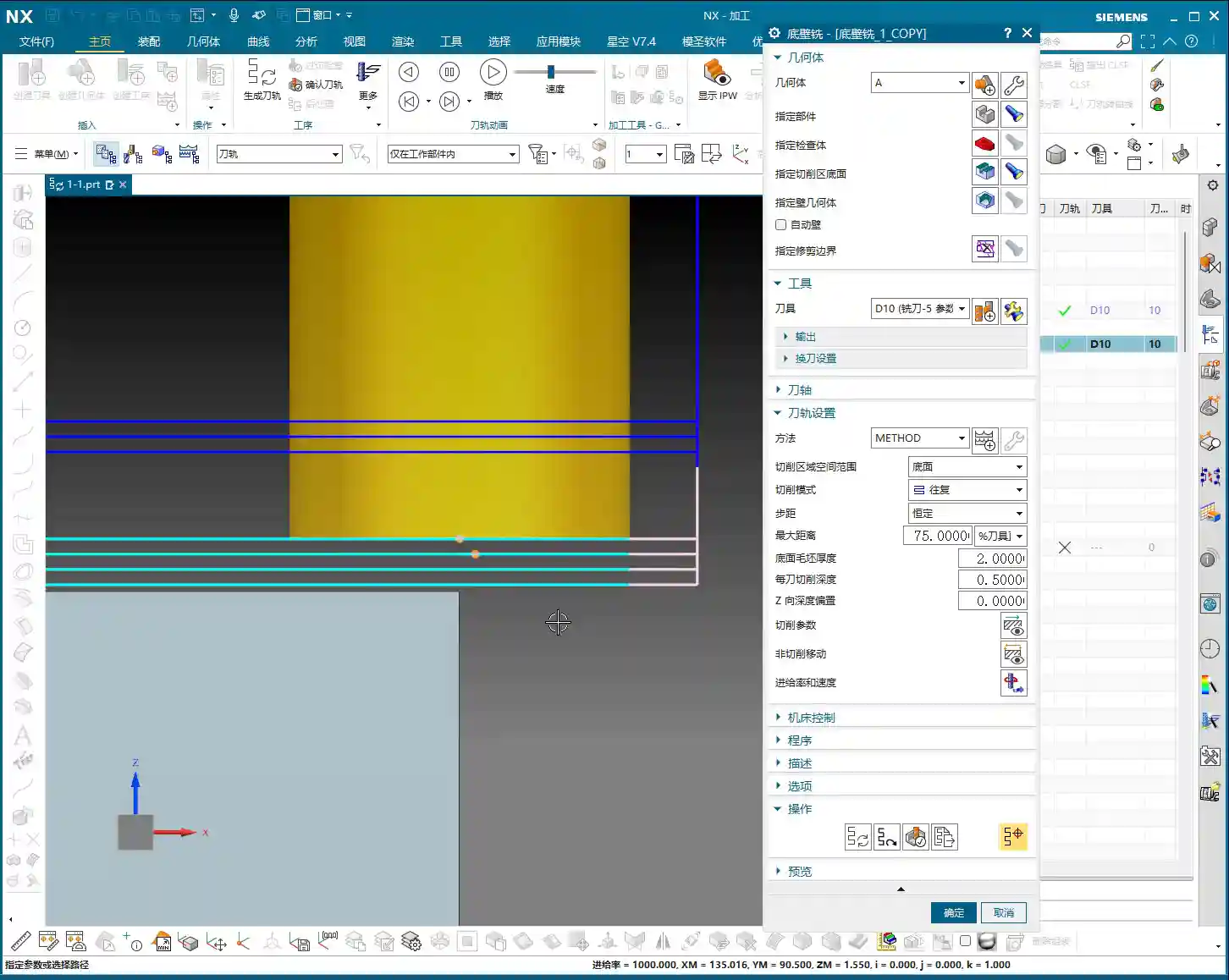
5. Pink: Retract – Safety First!
Once the job is done, the tool needs to leave. The pink toolpath that appears then is the Retract/Exit. The tool safely withdraws from the finished surface of the workpiece. Retraction also requires smoothness, especially during finishing passes, to avoid scratching the workpiece surface as the tool exits.
Master Wang’s Tip: Retraction might seem simple, but don’t get complacent. Pay attention, especially during retraction, as some materials tend to generate burrs. Ensuring the tool safely withdraws from the workpiece is fundamental.
II. Stepover: How the Tool Takes Its ‘Steps’
Stepover is the distance between adjacent toolpaths when the tool moves laterally. This parameter determines your machining efficiency and surface quality. In NX, it’s typically referred to as “lateral stepover” or “sideways stepover.”
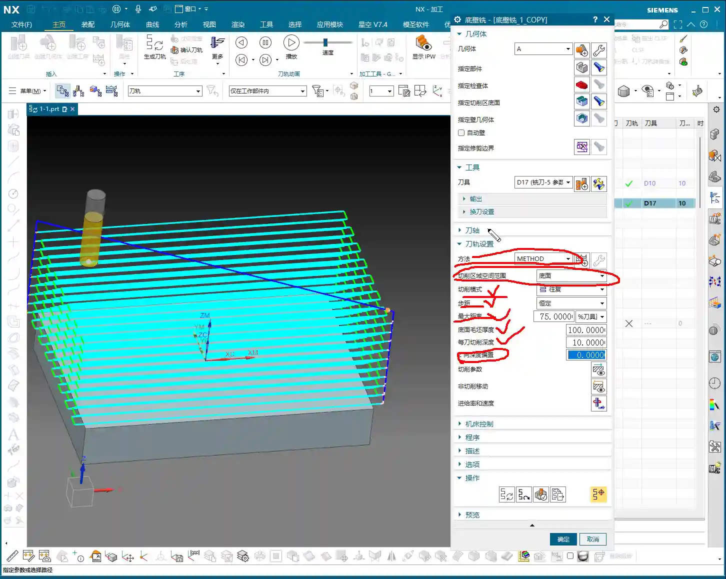

1. Percentage Stepover: Intelligently Adapts to the Tool
Listen up, the most commonly used and highly recommended option is percentage of tool diameter. For example, if you set it to 75%, this means the tool’s lateral movement distance each time will be 75% of the current tool diameter.
Master Wang’s Tip: Why use percentages? Because tools change! If you switch to a larger tool, the stepover automatically increases; with a smaller tool, it decreases accordingly. This saves you from recalculating and re-entering stepover values every time you change a tool, making it convenient and less prone to errors. For roughing operations like Face Milling, I often set the percentage to 85% or even 90% for efficiency, as long as the machine and tool can handle it – it’s a solid approach. However, for finish cuts requiring high surface finish, you might need to reduce it to 50% or even less, allowing the tool to make more passes for a smoother surface.
2. Absolute Stepover: For Specific Scenarios Only
Besides percentages, there’s Constant, which means setting a fixed stepover value, such as 8 mm (approx. 0.315 inch). With this method, if the tool diameter changes, the stepover remains the same unless you manually adjust it. This is suitable for situations with extremely strict stepover requirements or simple machining with fixed tool types. We generally don’t use it often.

Master Wang’s Tip: If you insist on using a fixed value, pay close attention. If you have a 10 mm (approx. 0.394 inch) tool and set an 8 mm (approx. 0.315 inch) stepover, that’s fine. But if you switch to a 5 mm (approx. 0.197 inch) tool and the stepover remains 8 mm, the tool will only cut a small portion, with the rest being air cuts, resulting in low efficiency. In some cases, a large stepover with a small tool can even lead to missed cuts or extremely poor surface quality. So, unless you have specific reasons, a percentage-based stepover is generally more reliable.
III. Depth of Cut (DOC) Per Pass: How Deep to Cut – A Vast Subject

The Depth of Cut (DOC) per pass is the distance the tool penetrates into the workpiece along the Z-axis each time. This parameter directly determines the cutting forces, tool life, machining time, and surface roughness. This is where your true craftsmanship is put to the test.
1. Stock Allowance at Bottom and Multi-Pass Cutting
In NX, there’s a parameter called “Stock Allowance at Bottom”, which refers to the total amount of material you need to remove from the bottom of the workpiece. For example, if your raw stock has 2 mm (approx. 0.079 inch) of allowance, then this parameter would be 2 mm.
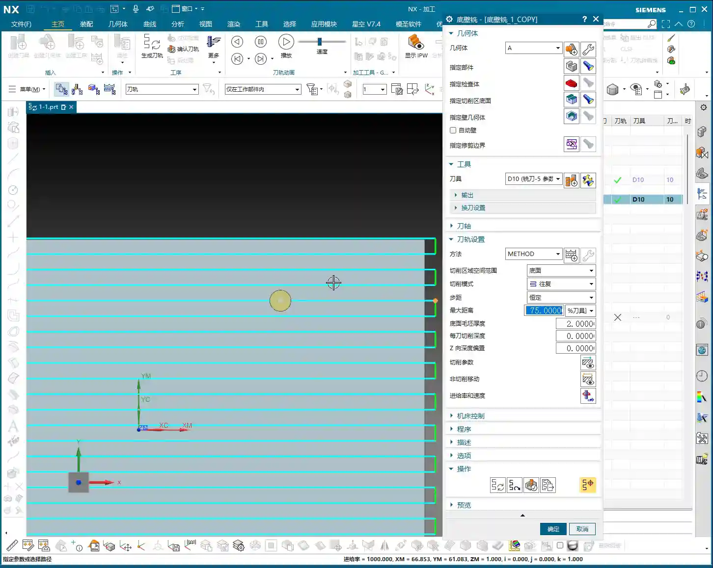
As for “Depth of Cut (DOC) per pass”, as the name suggests, it’s how deep you intend to cut with each pass. For instance, if the stock allowance is 2 mm (approx. 0.079 inch), and the Depth of Cut (DOC) per pass is 0.5 mm (approx. 0.02 inch), the tool will complete the 2 mm allowance in four passes.
Master Wang’s Tip: Multi-pass cutting is common sense! Especially for roughing and hard materials, you can’t expect the tool to take a huge bite in one go. How much to remove each time must be determined by a comprehensive assessment of material hardness, tool diameter, machine power, and spindle rigidity. For difficult-to-machine materials like titanium alloys and high-temperature nickel-based alloys, the Depth of Cut (DOC) per pass must be very cautious; it’s better to make more passes than to overload the tool. For common aluminum, you can afford a slightly larger DOC.
2. The Risk of Setting Depth of Cut (DOC) Per Pass to 0
Listen up, here’s a major pitfall! If you accidentally set the “Depth of Cut (DOC) per pass” to 0, even if the “Stock Allowance at Bottom” is 2 mm (approx. 0.079 inch), the tool will “pretend” to make only one cut, going straight from top to bottom. This is practically a suicide mission!
Master Wang’s Tip: Setting it to 0 means the program assumes you only need one pass to complete all cutting; it will attempt to remove all material at once. Do you think that’s possible? Unless the allowance is extremely small, or you have a super-powerful tool and machine. In general, this will lead to a series of severe consequences such as tool overload, tool breakage, machine collision, and scrapped workpieces. So, remember, you absolutely cannot easily set this parameter to 0! Unless you clearly know what you’re doing, and the allowance truly is 0, which typically only occurs during the final finishing pass.
3. Adjustment Strategies in Practice
In actual operation, the adjustment of Depth of Cut (DOC) per pass is flexible:
- Roughing: You can appropriately increase the Depth of Cut (DOC) per pass to prioritize efficiency. However, ensure that the cutting forces remain within the machine and tool’s capacity.
- Finishing: Typically, the Depth of Cut (DOC) per pass is reduced, sometimes even set to a very small value (e.g., 0.1 mm (approx. 0.004 inch) or less), to achieve better surface finish and dimensional accuracy.
- Material Characteristics: For difficult-to-machine materials like stainless steel and titanium alloys, the Depth of Cut (DOC) must be significantly smaller than for common steels or aluminum. High-temperature nickel-based alloys require even greater caution, as tool burnout is a common occurrence otherwise.
- Machine Power and Rigidity: For older or low-power machines, the Depth of Cut (DOC) cannot be too large; otherwise, it easily leads to chatter, affecting accuracy and surface quality. Only high-rigidity, high-power 5-axis machines can take deeper and faster cuts.
Summary: Pitfall Avoidance Guide
- Understand toolpath colors: Blue is rapid move – go fast; yellow is approach – be steady; light blue is actual cut – watch the sparks; green is traverse within cut – stay engaged; pink is retract – ensure safety. These colors correspond to different G-codes and machine states, forming the first step in accumulating experience.
- Stepover: Percentage is preferred: In most cases, using a percentage of tool diameter for stepover automatically adapts to tool changes, avoiding manual calculations and errors. For Face Milling roughing, it can be larger; for finishing, it should be smaller.
- Depth of Cut (DOC) per pass must NEVER be set to 0: Unless it’s a finishing pass with extremely minimal allowance, setting it to 0 means the tool will attempt to remove all material at once, highly likely leading to tool breakage and machine accidents.
- Adjust parameters based on practical conditions: The parameters in NX are fundamental, but how you ultimately adjust them depends on the material you’re machining, the tools you’re using, the machine’s performance, and the part’s accuracy and surface finish requirements. Observe and reflect frequently – that’s the way to mastery.
👤 About the Author:
The author is a veteran CNC machining professional with 15 years of industry experience, specializing in UG NX programming. This article is an original work representing personal practical insights.

⚠️ Copyright Notice: Unauthorized reproduction or distribution without prior communication is strictly prohibited.
Leave a Reply