📝 Key Takeaways: Master Wang personally shares practical insights into Siemens NX Guiding Curve machining. A deep dive into “Deform” and “Constant Offset” strategies, teaching you how to select guide lines, adjust direction and offset, and resolve chatter and sharp corner issues. Emphasizing practicality and efficiency, comparing it with Surface Milling to help you flexibly switch based on workpiece conditions, improving machining accuracy and efficiency. No more theoretical talk.
Hello everyone, I’m Master Wang. Today, we’re going to further explore the ins and outs of Siemens NX Guiding Curve machining. Last time, we covered some basics. This time, we’ll dive into practical examples to thoroughly explain how to use guiding lines, and how to use them smartly and effectively.
Core Concepts and Comparison of Guiding Line Machining
Listen up. In the machining business, rigidity is your worst enemy. Software offers countless functions, but not every one is suitable for all situations. Guiding Line machining is one of them; it has its advantages, but also its quirks. We need to understand it thoroughly.
“Deform” vs. “Constant Offset”: Different Paths, Same Destination?
As I’ve said before, the most common strategies in Guiding Line machining are “Deform” and “Constant Offset”. Many apprentices new to this often think they are completely different. However, for many simple planar or regular curved surfaces, the resulting toolpaths are actually quite similar.
Let’s take a face we previously machined using “Operation B” (Area Milling) and do a comparison. I’ll directly use “Guiding Line Machining”, define the part, blank, and cut area. Then, I’ll select two boundary lines as guide lines, choose the “Deform” method, and generate the toolpath. Lo and behold, it’s virtually identical to the toolpath generated by Area Milling. This is to set the stage for you; don’t get intimidated by the terminology right from the start.

Practical Case Study 1: Guiding Line Application for Planar Regions
Let’s machine the first face. Right-click, insert operation, and select “Guiding Line Machining”. Define the part and blank, then comes the critical step: defining the cut area. You can’t be sloppy here; the accuracy of your selection directly impacts the toolpath’s boundaries. This time, I’ll select the entire face to be machined.
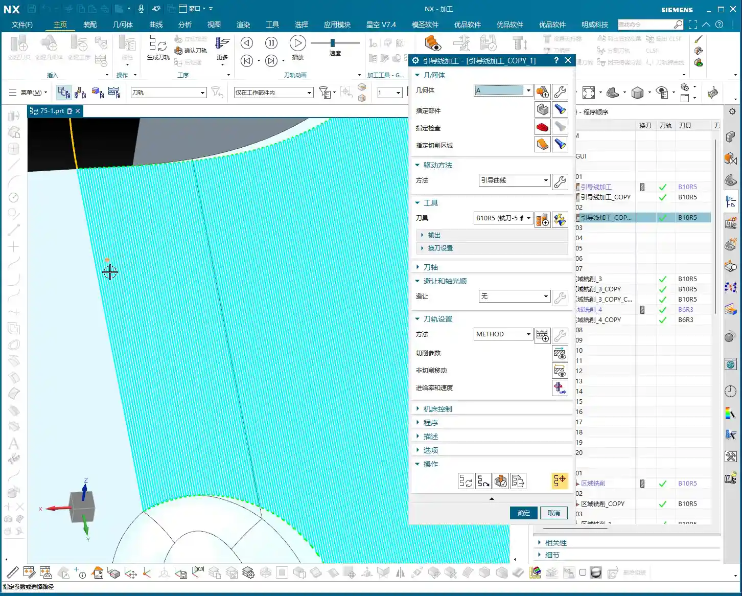
Since we’re using “Deform”, we need two guide lines. Select two edge lines of the machining area, ensure their directions are consistent, and confirm. Once generated, you’ll see the toolpath is quite smooth, just like the previous Area Milling program.
Next, let’s copy the operation and change the method to “Constant Offset”. Constant Offset usually only requires one guide line. I’ll select the line on the left and set the direction to “Away from Guide Line”. Generate the toolpath, and the result is again not fundamentally different from the “Deform” method. So, for regular regions, these two methods are often interchangeable, depending on your personal preference and the convenience of available lines.
Avoiding Pitfalls: The Wisdom of Guiding Line Selection
Now, this next case needs some serious discussion. We’re looking at an area with corners, slightly more complex, and this is where many engineers start getting confused with Guiding Line machining.

The Root Cause of Chatter: Short Guiding Lines and Improper Direction
I copied an operation and changed the cut area to this cornered region. Still using the “Deform” method, I selected two shorter edge lines as guide lines. After generating the toolpath and running a simulation, “Oops, chatter!” What’s more, the toolpath at the corner turns sharply, even somewhat circling. Why is this happening?
Look closely: the guide lines themselves are short. To cover the entire cut area, the toolpath is “forced” to bend and lift. Furthermore, if the guide line direction is chosen incorrectly – for example, if it should offset to the left but you selected right – the software will stubbornly try to calculate it, resulting in a series of useless tool lifts (chatter) and irrational movements.
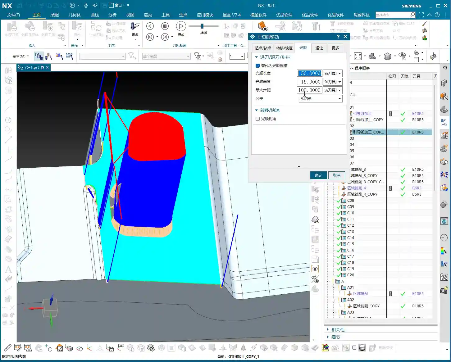
Therefore, there’s a crucial prerequisite here: guide lines should be as long and smooth as possible, and effectively represent your desired toolpath direction. If the line is too short, or inherently unsuitable as a guide, the resulting toolpath will undoubtedly be suboptimal.
Direction and Offset: Don’t Blindly Fight the Arrows
Next, I switched the method back to “Constant Offset”, selected a relatively shorter guide line, set it to “Away from Guide Line”, and initially chose “Right Side” for the offset direction. What happened? NX immediately gave me an error or warning, and the toolpath generated was a complete mess. Why?
Because the arrow direction of the line I selected determines what is “Left” and “Right” relative to it. I initially misunderstood, thinking the arrow pointed one way, and the left side was inside the part. Only after changing the offset direction from “Right Side” to “Left Side” did the toolpath generate correctly. This is a reminder to everyone: clearly observe the arrow direction of the guide line before determining “Left Side,” “Right Side,” “Away,” or “Toward”. Don’t assume, or this single detail could cost you half a day!
Guiding Line Length: Key to Smooth Toolpaths
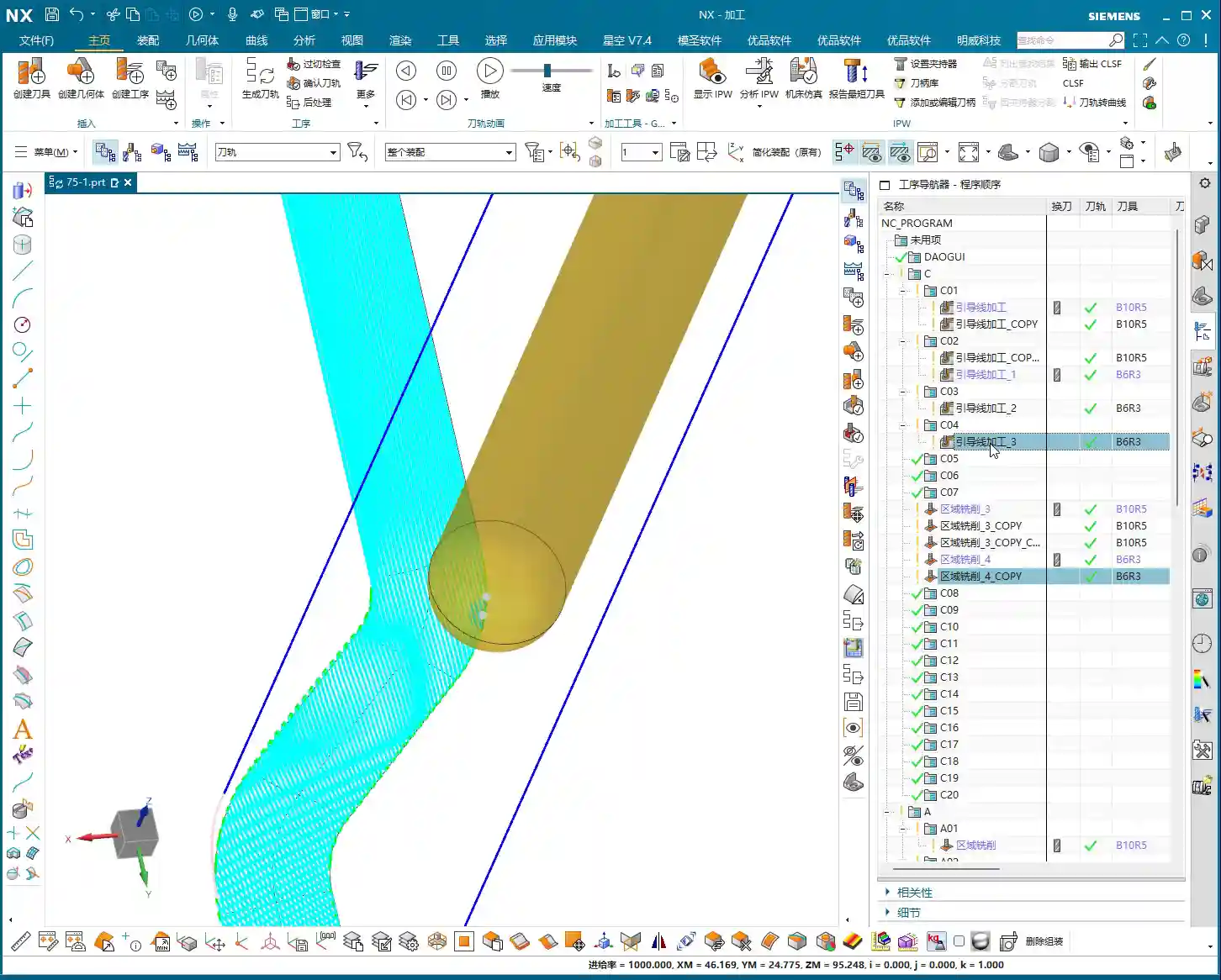
Even with the correct direction, because my chosen guide line was still relatively short, the generated toolpath at the corner still had unnecessary “flourishes” of bending. What does this tell us? Short guide lines, even with the correct direction, make it difficult to generate a truly smooth toolpath without superfluous movements.
Therefore, I switched to another guide line that was longer and spanned the entire region. I again selected “Constant Offset” with a “Left Side” direction. This time, the generated toolpath was significantly better and much smoother. While there might still be a slight curve at the outermost corner, it’s now perfectly acceptable.
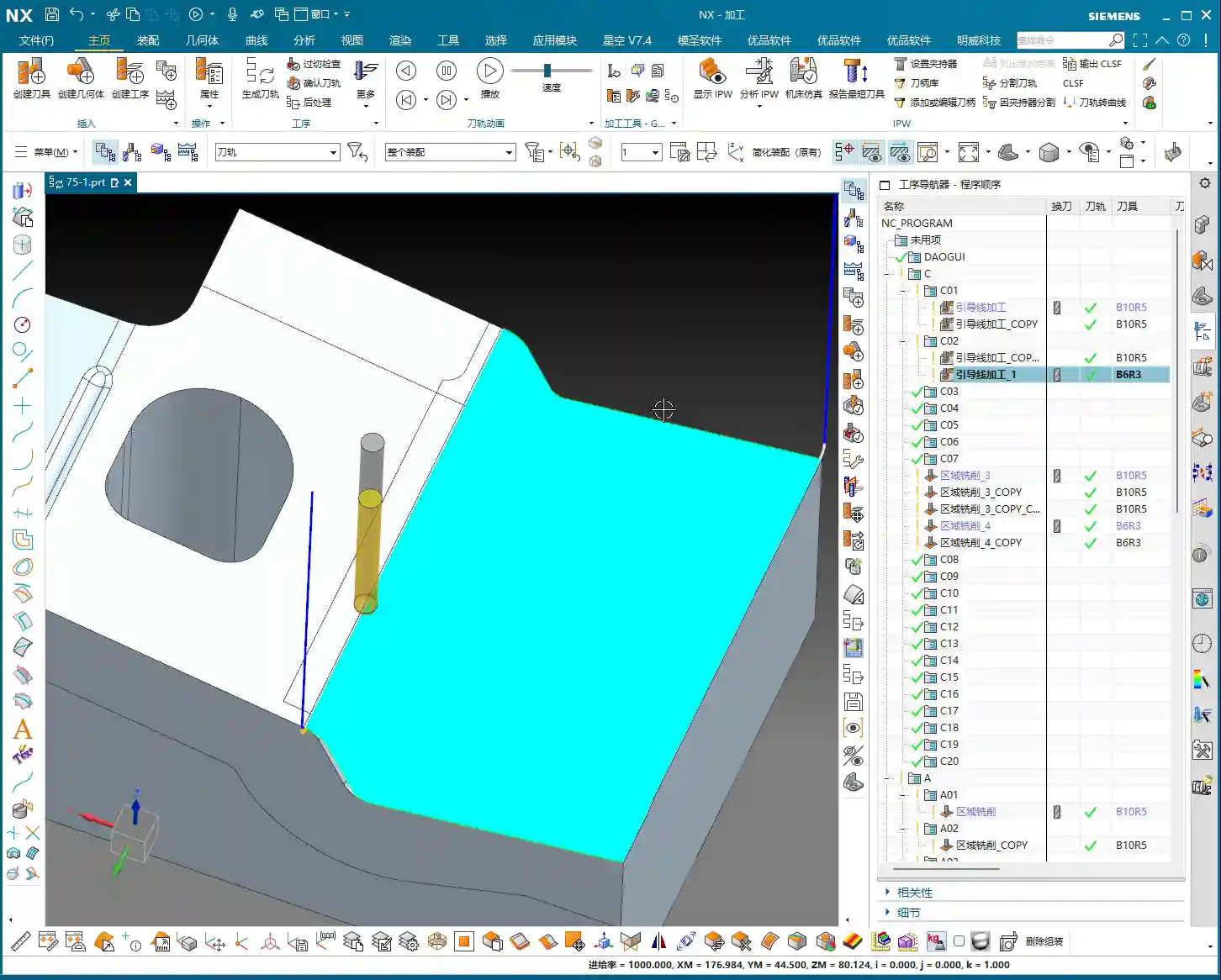
So, here’s some practical advice from Master Wang: When selecting guide lines, choose long over short, and straight over curved. The better the guide line represents your desired machining direction, the smoother your toolpath will be, leading to higher efficiency and lower scrap rates.

Applicable Scenarios and Limitations of Guiding Line Machining
Through the examples above, you should now see that Guiding Line machining has its advantages, such as high flexibility in controlling toolpath direction using lines. However, it also has limitations.
Not a Panacea: Surface Milling is Sometimes Superior
For the type of machining surface with corners and irregular boundaries mentioned above, my final conclusion is that “Surface Milling” (our “Operation B” from before) might be better suited for machining such regions. Surface Milling offers more specialized parameters and algorithms for optimizing toolpaths when dealing with complex boundaries and Corner Cleanup, making it less prone to chatter and sharp turns that can occur due to line shape limitations in Guiding Line machining. Don’t just get dazzled by fancy software features; use whatever method can machine the part quickly, efficiently, and with high quality!
Of course, Guiding Line machining isn’t incapable, but you might need to spend more time adjusting guide lines, experimenting with different offset methods, or even using “Smooth” toolpath parameters to reduce chatter and bending. Even then, in certain corners, it might still perform poorly because it lacks dedicated “Corner Cleanup” options like Surface Milling.

Guiding Lines: A Surprising Fix for Chatter – A Special Case
However, Guiding Line machining also has its “secret weapon” applications. For instance, I once had an operation machining from top to bottom where Surface Milling would produce chatter due to terrain changes. At that point, I tried Guiding Line machining, selecting appropriate guide lines. Even if my guide lines were somewhat “broken” or didn’t fully cover the entire region, as long as I correctly selected the cut area, the software could still generate a toolpath.
After some experimentation, I found that by selecting shorter guide lines, I could better control the toolpath, avoiding the extensive chatter that occurred with Surface Milling. Once this program was generated and compared to the previous one, you’d find that the chatter was indeed greatly reduced, even eliminated. This demonstrates that for certain specific chatter issues, Guiding Line machining can be a simpler and more effective solution.
This validates a point Master Wang has always emphasized: There’s no absolute good or bad, only what’s most suitable.
The “Temperament” of Siemens NX Guiding Line Machining: Errors and Solutions
Finally, let’s talk about a “quirk” of Guiding Line machining: it sometimes throws errors or warnings. This is common, so don’t panic! Most of the time, it’s because the guide line you’ve selected has the wrong direction, or the offset method is unsuitable. Just try changing the direction or switching the offset mode (e.g., from “Away” to “Toward,” or “Left Side” to “Right Side”), and you can usually resolve the issue.
Summary: Pitfall Avoidance Guide
- Guide Line Selection: Prioritize selecting long, straight, and smooth lines as guide lines, as they better represent your desired toolpath direction. Avoid choosing lines that are too short or overly complex/curved.
- Direction and Offset: It is crucial to carefully observe the guide line’s arrow direction before accurately selecting “Left Side,” “Right Side,” “Away from Guide Line,” or “Toward Guide Line.” Incorrect direction selection is the most common mistake for beginners and a primary cause of errors and irrational toolpaths.
- Chatter Resolution: When chatter occurs, first check if the guide line selection is appropriate. If the Guiding Line method doesn’t resolve it, you can try switching to other machining methods (such as Surface Milling), or optimizing by adjusting “Smooth” parameters. In special cases, selecting shorter, more precise guide lines can actually resolve localized chatter.
- Applicable Scenarios: Guiding Line machining performs well on regular planar or curved surfaces and has distinct advantages for specific requirements (e.g., controlling toolpath direction, avoiding certain chatter issues). However, for complex Corner Cleanup and highly irregular regions, methods like Surface Milling may be more efficient and stable.
- Error Handling: Guiding Line machining occasionally throws errors, usually due to selection issues. Boldly try changing the guide line selection, direction, or offset mode, and it will likely resolve the problem.
Remember, the core principle remains: the ultimate goal is to machine parts efficiently and with high quality, reducing costs. Don’t just rely on software simulation; the real test is when the tool meets the material!
👤 About the Author:
The author is a veteran CNC machining professional with 15 years of industry experience, specializing in UG NX programming. This article is an original work representing personal practical insights.
⚠️ Copyright Notice: Unauthorized reproduction or distribution without prior communication is strictly prohibited.
Leave a Reply