📝 Key Takeaways:
Siemens NX Roughing Tutorial for Rotational Parts
Hello everyone, I’m Master Wang. Today, let’s talk about the first roughing operation f…
Hello everyone, I’m Master Wang. Today, let’s talk about the first roughing operation for a rotational part. Listen up, this job looks simple, but there are a lot of hidden tricks. Those fancy theories from textbooks, when you get them on our shop floor, you need to learn how to apply them flexibly to truly produce quality work and save costs.
Step One: Stock Modeling – The Foundation of Everything
As I mentioned, this part is a rotational component. The requirements are clear: the outer diameter and some internal areas have already been turned smooth by the lathe operator. What we need to machine are the remaining “material allowances.” Therefore, the creation of the stock model must accurately reflect the actual situation; don’t just rely on guesswork, or issues will arise as soon as the tool engages.
Accurately Replicating the “As-Received” State
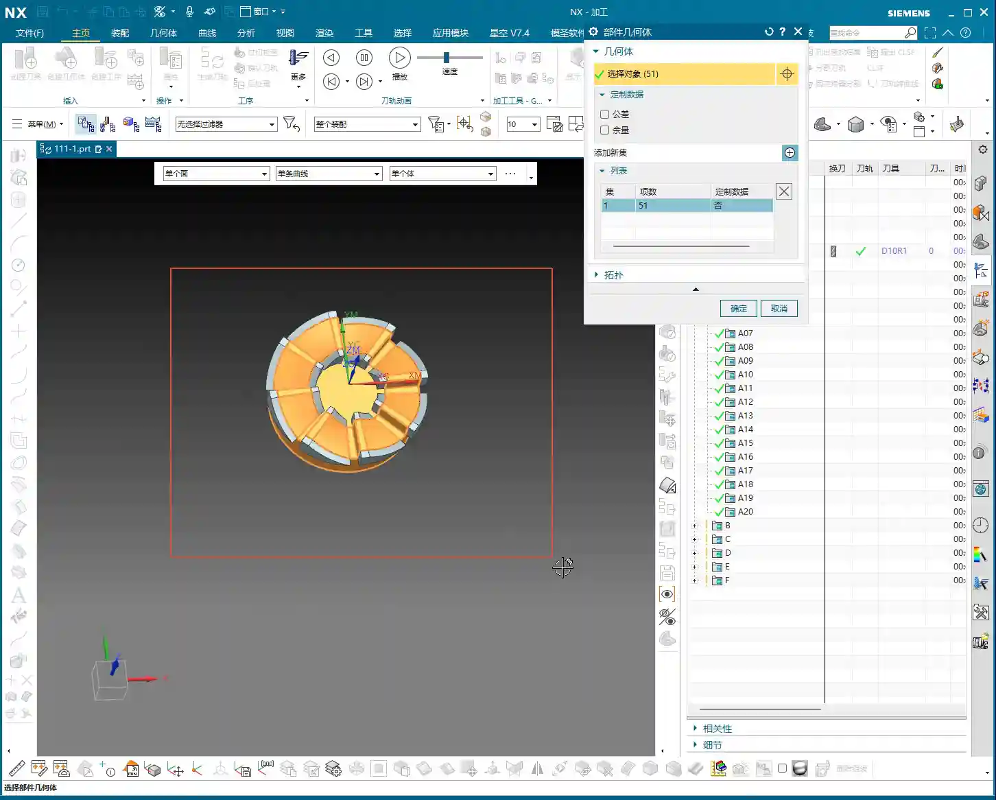
When modeling, we first need to establish a general shape. Using the “Thicken” function in NX, slightly extend the area we need to machine outwards to form a “stock shell.” Then, based on the drawing requirements, use “Replace Face” or “Extrude Subtract” to incorporate the areas that have already been turned, such as the outer diameter and internal through-holes, into the stock model. Remember, the stock model must truthfully reflect the part’s state before entering our machining process; this is the basis for subsequent toolpath calculations.

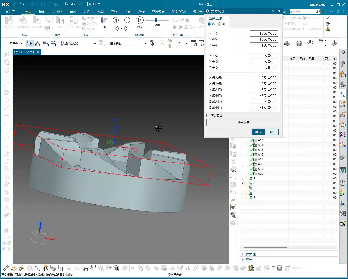
Take this part, for instance: there’s an 80mm diameter hole (40mm radius) internally that has already been turned through. So, we draw an 80mm diameter circle and then Extrude Subtract it. This way, our NX software understands which areas require material removal and which areas are already finished. Don’t underestimate this step; an inaccurate stock definition can lead to minor issues like wasted time from air cuts, or major issues like overcutting and scrapping parts.
Coordinate System and Layer Management: As Crucial as 5S in the Workshop
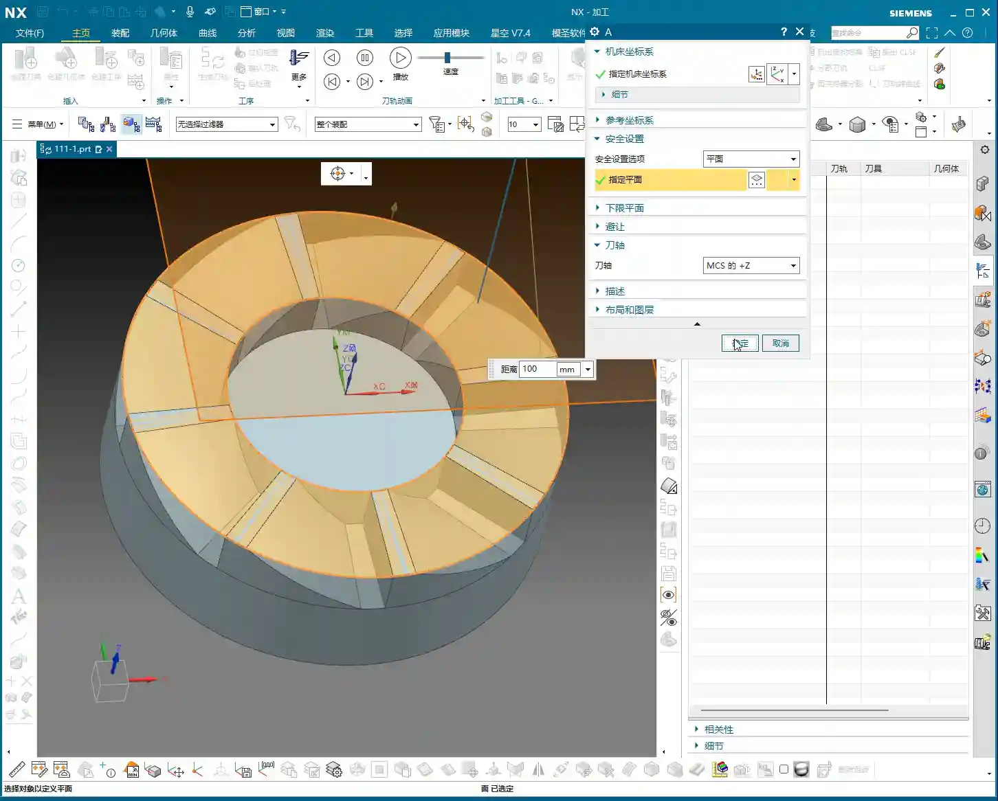
After creating the stock model, I habitually move it to Layer 100. This isn’t just a quirk; it’s to clearly distinguish between the part model, stock, fixtures, and toolpaths during subsequent programming. Good layer management ensures the entire project is organized, making it easy to find and modify. The Work Coordinate System (WCS) is typically set at the part’s center, top, or bottom, for convenient positioning. This is just like setting up a part and performing tool offsetting on the machine; if the datum isn’t accurately located, everything else is futile.
Step Two: Part Geometry Analysis and Machining Strategy – Understand the Geometry, Master the Process

With the part model and stock prepared, now comes the critical step: analyzing the part. This part isn’t large, with a diameter of 150mm and a thickness of 18mm. But size isn’t the only factor; we must examine its geometric features. Using NX’s “Slope Analysis” function, we can see that most of this part is planar, without complex undercuts or deep pockets. This indicates that our machining difficulty isn’t particularly high, at least in terms of tool selection, where we won’t need many specialty tools.
Minimum Feature and Tool Selection
After measuring, the narrowest area on the part, the “small root,” is only 6mm. This is an important signal! It directly determines the size of our finishing tools. Since the minimum feature is 6mm, our subsequent corner cleanup or finishing tools must be able to access this 6mm area. So, I have a clear idea: a 6mm flat end mill or ball end mill will definitely be needed.
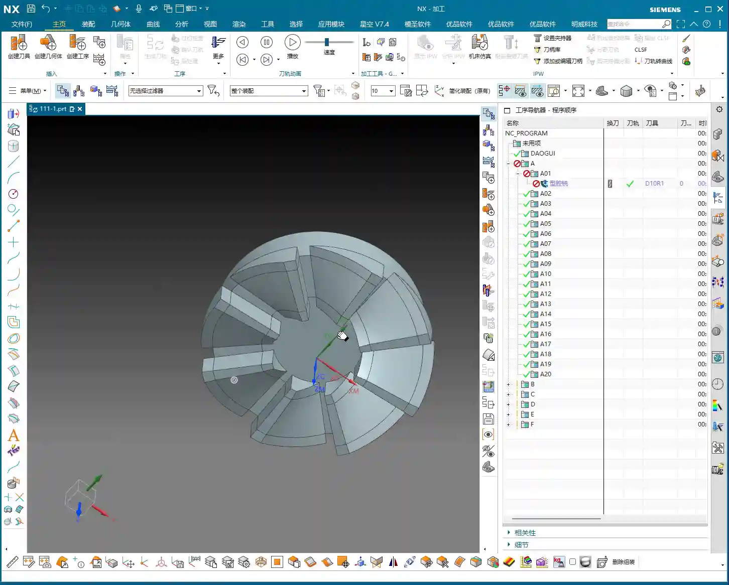
For roughing, based on the stock allowance and part dimensions, we cannot use too small of a tool. Here, we plan to use a 10mm bullnose end mill (e.g., D10R1) for the initial roughing, allowing for a large Depth of Cut (DOC) and high efficiency. Then, a 6mm tool will be used to clear the remaining material left by the 10mm bullnose, which is commonly referred to as “secondary roughing” or “rest milling.” Finally, if surface finish or smaller radii are required, a ball end mill can be considered for finishing passes.
This combination strategy achieves both efficiency and accuracy. Don’t just think about using one tool for the entire process; that’s a “one-track mind.” Machining requires strategy.
Step Three: Siemens NX Roughing Toolpath Execution and Optimization – From Part Modeling to Toolpath Execution

Once the strategy is set, we proceed to create toolpaths in NX. For roughing, we’ll use the “Cavity Milling” operation, which is excellent for processing such shapes. Select a D10R1 tool (10mm diameter, 1mm corner radius), and set the Depth of Cut (DOC) based on the material and machine rigidity. Here, let’s start with a 0.3mm Stepover for generation.
Initial Toolpath Issues: Air Cuts and Frequent Engagements/Retracts
Once the toolpath is generated, don’t just look at the surface; we must simulate it and judge it based on experience. Look, this toolpath is “zigzagging back and forth,” with long lead-in/lead-out paths, and it tends to “wander around” in the air. What are these? These are unnecessary air cuts and frequent acceleration/deceleration cycles. The machine runs back and forth, the spindle speeds up and slows down repeatedly. This not only wastes time but also wears down the machine, and more importantly, affects machining quality. Such a toolpath, when brought to the shop floor, machinists would immediately spot issues, and it would never be put on a machine.
Master Wang’s Advanced Technique: Cleverly Using Auxiliary Geometry to Tame Toolpaths
So, how do we solve this problem? Textbooks might tell you to adjust cutting parameters, but that treats the symptoms, not the root cause. Our secret tip is to create auxiliary geometry. This isn’t some advanced function; it’s simply NX’s most basic “Thicken Surface” feature!
- Take the boundary surfaces that cause the toolpath to oscillate back and forth and “Thicken” them slightly outwards.
- Use these thickened surfaces as “Check Geometry” or “Trim Boundaries”. This ensures the tool avoids these auxiliary bodies during machining or is forced to move only within them.
Through this method, we manually establish more logical “travel paths” for the toolpath. The tool can no longer wander arbitrarily; it will be “planned” to move more smoothly, lead-ins and lead-outs are no longer “unnecessarily protracted,” and air travel is significantly reduced. As you can see, after modification, the toolpath becomes noticeably cleaner and smoother, with crisp lead-ins and lead-outs. This is the kind of toolpath that can run efficiently on the machine.

Details Determine Success: The “Extension” Parameter for Lead-in/Lead-out
Even with auxiliary geometry, sometimes the lead-in/lead-out distance can still be a bit long. At this point, you need to fine-tune the “Extension” parameter. Slightly shorten the extension distance so the tool doesn’t need to travel excessive distances when leaving the workpiece. This is another accumulation of efficiency, bit by bit. Don’t underestimate this small detail; saving a few seconds per part adds up to hours a day, and over a year, the cost savings are substantial.
Step Four: Preparing for Secondary Roughing – Striving for Perfection
After completing the roughing program, don’t rush to remove the part from the machine; we still need to consider “secondary roughing.” Secondary roughing involves using a tool smaller than the roughing tool, or a flat end mill with a smaller Stepover, to remove the remaining material after roughing, preparing for finishing. We previously planned to use a 6mm tool for this task.
Following the same principle as roughing, create a “secondary roughing” operation, select our 6mm tool, and then set a smaller cutting Stepover based on the material and requirements. The stock must also be accurately defined; this time, the stock is the remaining material left from the previous roughing step. This step ensures that subsequent finishing tools can cut with a stable and uniform Depth of Cut (DOC), which guarantees the final part’s accuracy and surface quality.
Remember, no single operation is isolated. The quality of the preceding operation directly impacts the efficiency and effectiveness of the subsequent one. You need to have a “holistic view” when working; don’t just focus on the current cut.
Summary: Pitfall Guide
Let me, Master Wang, summarize a few common “pitfalls” for beginners when roughing rotational parts, as discussed today:
- Inaccurate Stock Definition: This is the primary cause of issues! If the stock doesn’t match the part model, toolpaths are prone to errors, leading to overcutting or air cuts. Always model the stock precisely based on the actual as-received material.
- Blindly Generating Toolpaths: Don’t assume that toolpaths calculated by the software are always optimal. NX is a tool, but human expertise is key. Observe toolpaths carefully, simulate cutting, and check for unreasonable lead-ins/lead-outs or air moves.
- Ignoring the Role of Auxiliary Geometry: Using “Thicken Surface” as auxiliary geometry, as we did today, is an advanced application in NX programming that can significantly optimize toolpaths and improve efficiency. These “unwritten rules” can help you avoid many detours.
- Neglecting Tool-to-Part Feature Matching: The minimum feature size determines the limits for corner cleanup or finishing tools. The selection of roughing and finishing tools should form a logical “sequence.”
- Disregarding Layer Management: A messy project file will make future maintenance and program modifications a nightmare. Develop good habits; categorize and organize geometry and toolpaths.
- Focusing only on programming, not on cost-efficiency: Our ultimate goal in manufacturing is to produce qualified parts while also considering cost and efficiency. Any toolpath optimization must ultimately translate into “saving money, saving time, and saving effort.”
Alright, that’s all for today’s sharing. Go practice more, think more, and turn these practical experiences into your own expertise! If you have any questions, come ask me next time.
👤 About the Author:
The author is a veteran CNC machining professional with 15 years of industry experience, specializing in UG NX programming. This article is an original work representing personal practical insights.
⚠️ Copyright Notice: Unauthorized reproduction or distribution without prior communication is strictly prohibited.
Leave a Reply