📝 Key Takeaways: Master Wang demonstrates essential pre-programming part analysis in Siemens NX 1980. Learn to inspect dimensions, fillets, and slopes to develop robust, efficient machining strategies and prevent costly reworks.
Hello everyone, I’m Master Wang. Starting from this lesson, we’ll officially delve into Siemens NX programming. Today, let’s talk about how to “see through” a part before programming to avoid detours!
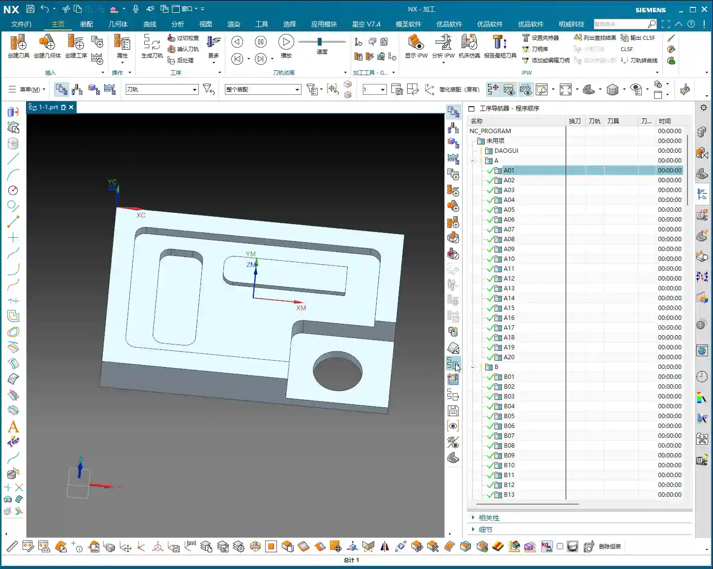
Step One: Understand Basic Part Dimensions and Raw Material Size
Listen up! When you get a part, the first thing isn’t to rush to click the mouse, but to “measure its three dimensions”! It’s like knowing your clothes size; machining is the same.
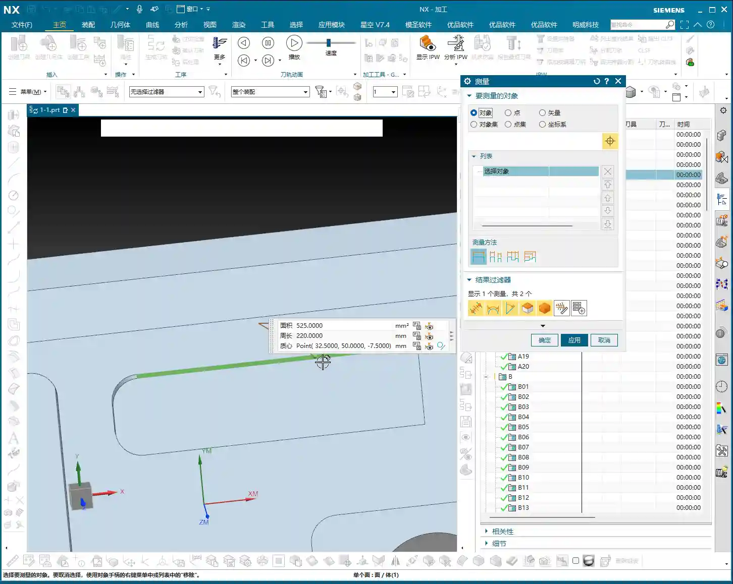
Measuring Finished Dimensions and Raw Material Size
In Siemens NX, we need to use the “Measure Entity” function. Click it open, measure the part’s length, width, and height. For this example, the length is 270mm, the width is 180mm, and the height is 40mm. Keep these finished dimensions in mind. At the same time, you need to know the raw material’s size; this determines your roughing stock.
Master Wang’s Tip: Don’t just rely on the software display. In actual machining, ensure your raw material has sufficient allowance. You don’t want to find out you’re short on material at the machine, or that the allowance is too large, leading to excessive air cutting time!
Step Two: Detailed Inspection of Part Geometry (Fillets and Slopes)
After measuring the overall dimensions, it’s time to act like a detective and thoroughly inspect every corner and edge of the part. Especially fillets and slopes, as they directly influence your tool selection and machining strategy.
Analyzing Fillet Sizes
We’ll use the “Geometric Properties” function to check fillets. For instance, if your fillet radius is R10, your tool selection needs careful consideration. Using a D20 (diameter 20mm) end mill to machine this fillet is perfectly fine; it will clear it precisely. Of course, a D16 or D10 tool can also be used, as long as the tool diameter is less than or equal to 20mm. But don’t even think about using a D1 tool; that’s just unrealistic. It’ll be incredibly inefficient and you’ll likely break the tool.
So, the principle of tool selection is: it must be able to reach the desired feature while also considering efficiency and cost. Don’t use a cannon to kill a mosquito, nor a sewing needle to chisel a rock!
Checking Side Wall Slope (Perpendicularity)
Slope analysis is extremely important! Open the “Draft Analysis” function and carefully examine the side walls. If all side walls appear green, it means they are all vertical faces (straight walls), without any undercuts or tapers. This simplifies the part, allowing you to machine it directly with a standard end mill, without needing special processes. If you find any areas with incorrect colors, like red, there might be undercuts or sloped surfaces, and you’ll need to consider using ball end mills, tapered tools, or 5-axis machining.
Remember: understand the part’s “temperament” to prescribe the right treatment, so you don’t get flustered at the machine.
Step Three: Establish a Standardized Program Management Process
After analyzing the part, we move on to programming. But programming isn’t random; it needs a method. Especially for beginners, a standardized program management process is crucial.
Creating Operations in Sequence
In Siemens NX, right-click on a folder -> Insert -> Operation. Pay attention here: operations must be created in the actual machining sequence. For example, roughing first, then semi-finishing, and finally finishing pass, from top to bottom, outside to inside. You can’t just jump to programming a specific hole because you want to machine it first; that will lead to big problems on the actual machine!
Imagine this: you still have a lot of raw material on top that hasn’t been cleared, and suddenly you go to machine a small hole. Isn’t that just asking for a tool crash? So, roughing before finishing, outside before inside, face milling before hole drilling – these are fundamental principles. While we can be a bit more flexible during practice, on a real machine, not a single step can be wrong!
Learning the Practical Use of Each Programming Command
Our current learning focus is to understand how each programming command is used, such as Face Milling, Planar Profile, Cavity Milling, Depth Profile, Flow Cut, Curve Drive, and so on. Knowing their individual “personalities” and applicable scenarios will allow you to program with ease.
Remember, these commands are like your toolbox. Understanding the purpose of each tool will make you a true “master operator”!
Summary: Pitfall Avoidance Guide
- Blindly starting is a major taboo! Always thoroughly analyze part geometry before programming, including dimensions, fillets, and slopes. Don’t overlook any detail.
- Tool selection isn’t guesswork! Choose tools rationally based on fillet sizes and side wall characteristics, balancing machining efficiency and cost. Avoid using small tools for large tasks or large tools for small holes.
- Program sequence is critical! During actual machining, strictly follow the “roughing before finishing, outside before inside” principle for operation arrangement to prevent tool crashes and ensure safe and efficient production.
- Take detailed notes! Develop a good habit of recording the analysis results and tool selection strategies for each part, building your own machining experience database.
Leave a Reply