📝 Key Takeaways:
Siemens NX in Practice: Pre-Programming Analysis and Surface Patching for Disc Parts
Alright, listen closely, folks. Today, Master Wang w…
[VIDEO_HERE]
Alright, listen closely, folks. Today, Master Wang will walk you through the ins and outs of machining these disc-type parts. Don’t think it’s simple just by looking at it; an inexperienced machinist will stumble right into the pitfalls here. We’re not going to waste time on abstract theories. Let’s dive right in and talk about how to machine this thing quickly, accurately, and cost-effectively.
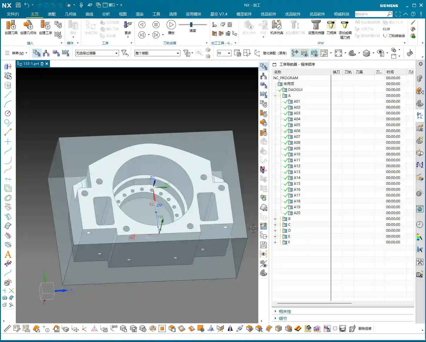
Step One: Blank and Fixturing – A Solid Foundation is Key
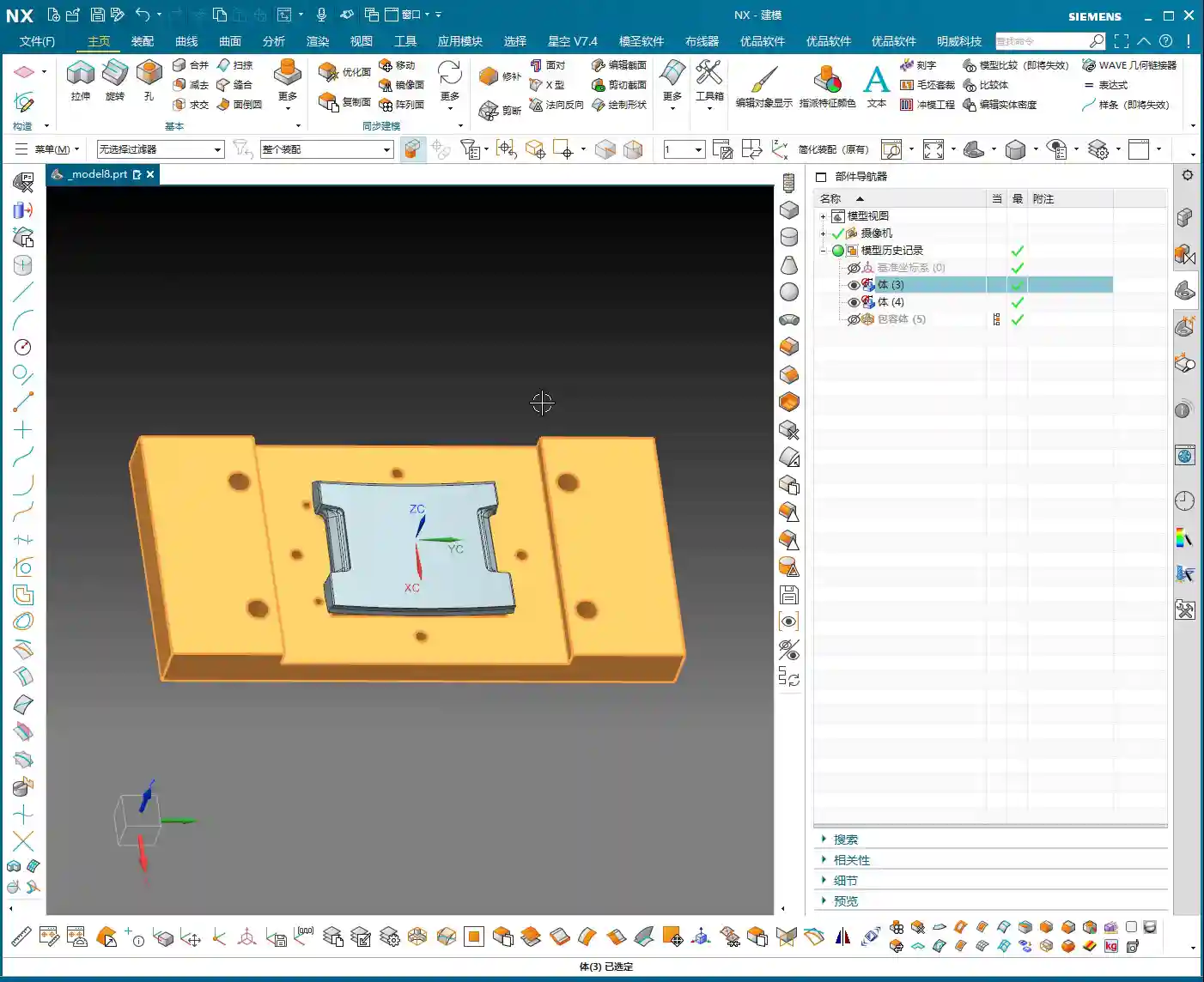
Once you get the drawing, don’t rush to open the software. First, review it in your head. This part, by visual inspection, appears to be a cylindrical blank. Remember this: if the blank is defined incorrectly, everything that follows is pointless.
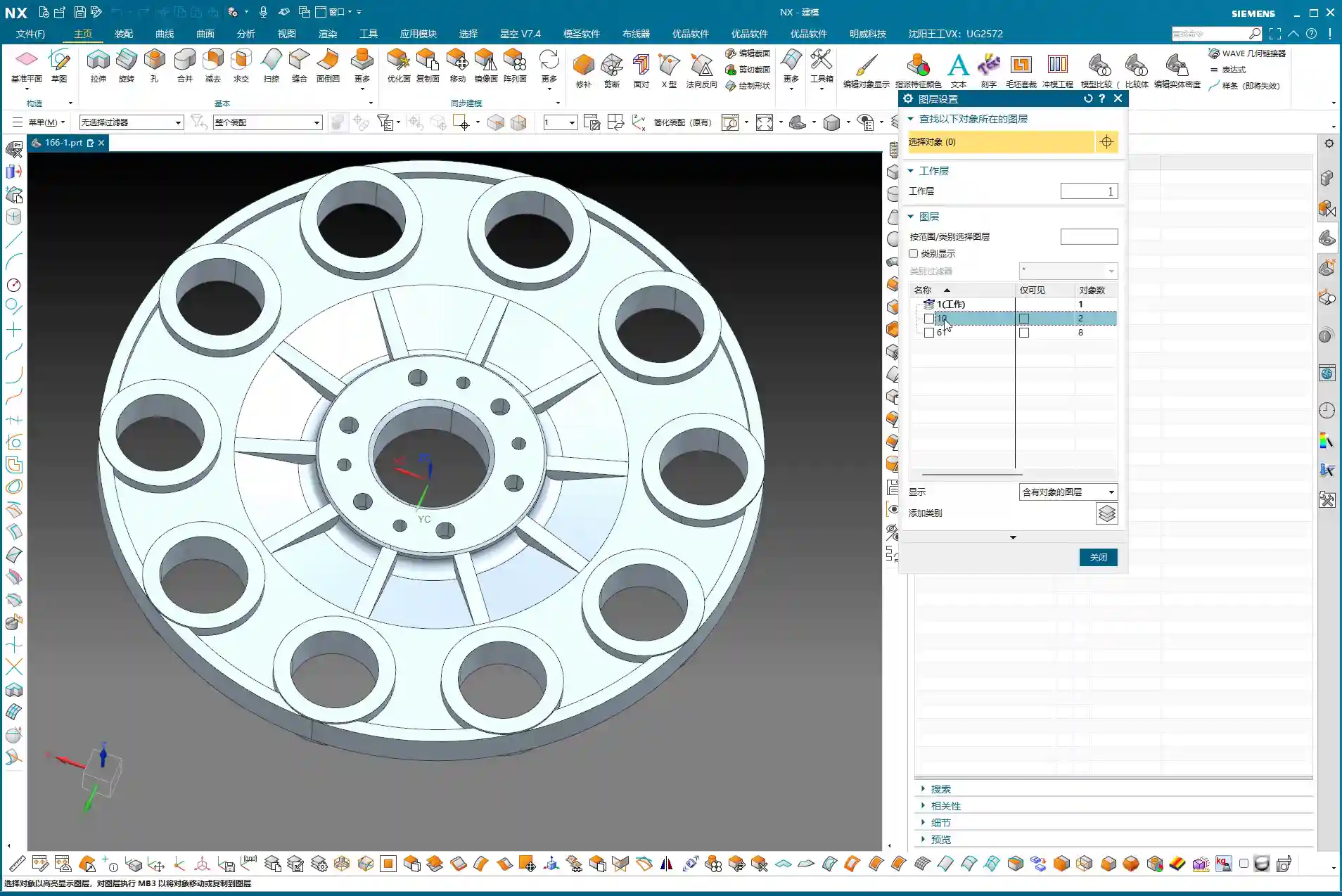
Layer Management for Blanks and Parts
I habitually separate the blank and the finished part. This keeps things clear and prevents confusion. For example, put the blank on Layer 10 and the part on Layer 100. Just activate the layer you need; it’s clean and efficient! While this is a software operation, it’s also a logical extension of managing drawings in the workshop. Don’t underestimate these details.
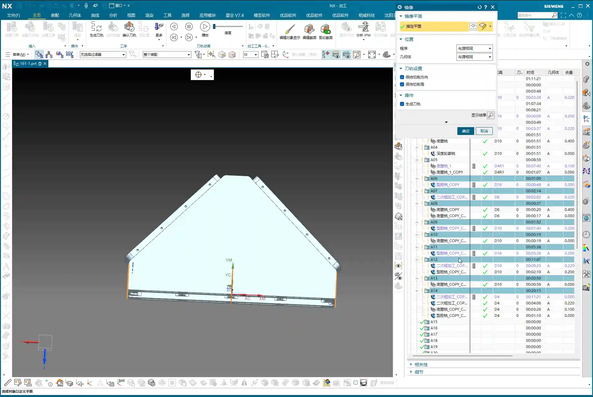
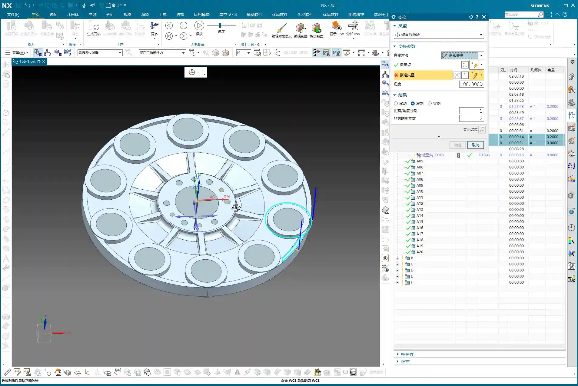
Fixturing Strategy: Flip-Machining is Standard
For these disc parts, both sides need to be machined, so the most common approach is flip-machining. Machine the backside first, then flip it over to machine the front. For fixturing, let’s start with the most conventional method. As for the specific fixture, that depends on your actual machine and workpiece situation; you need to be flexible. But the core idea is: ensure rigidity, minimize deformation, and facilitate flipping. When machining the first side, the Work Coordinate System (WCS) can initially be set to the bottom surface. Then, upon measurement, you find it’s offset by 1 mm in the Z-direction. That’s easy to fix: dynamically adjust the WCS, raising the Z-axis by 1 mm. This ensures it perfectly aligns with the machining surface, leading to stable and accurate tool paths.

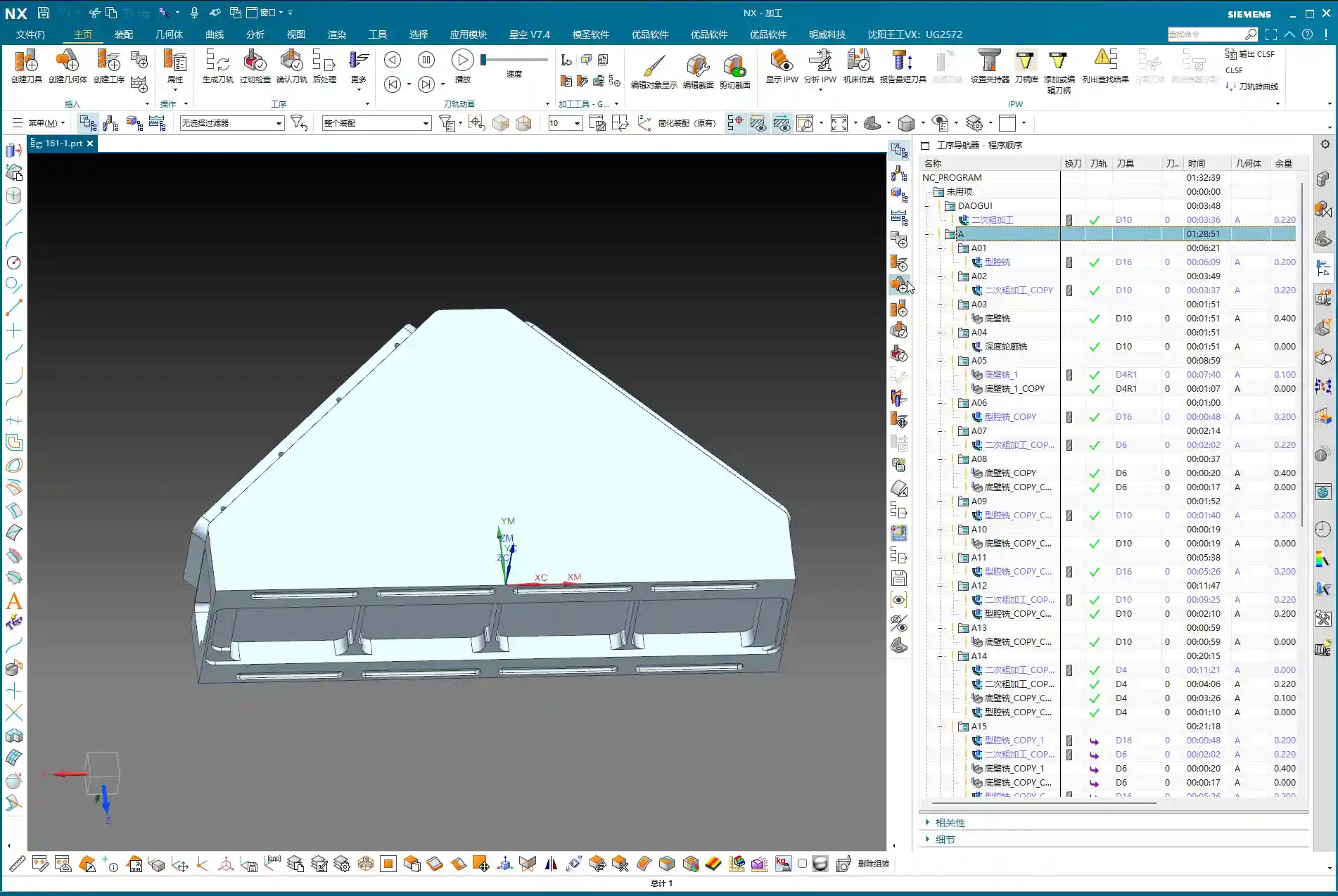
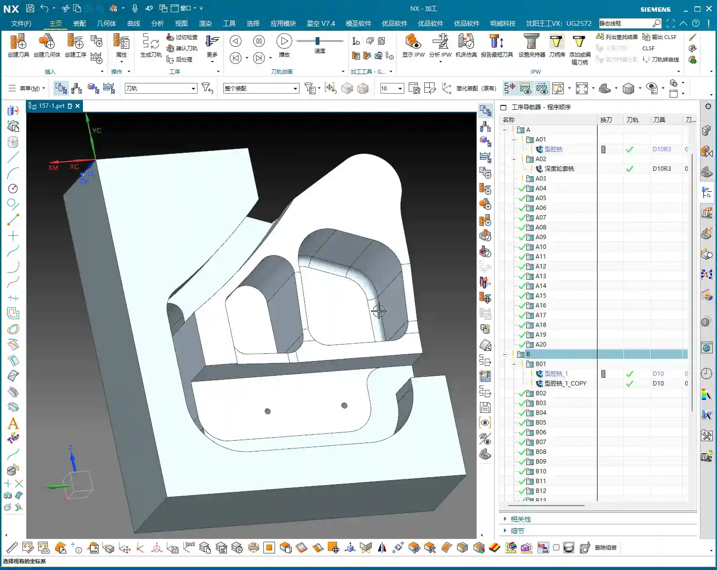
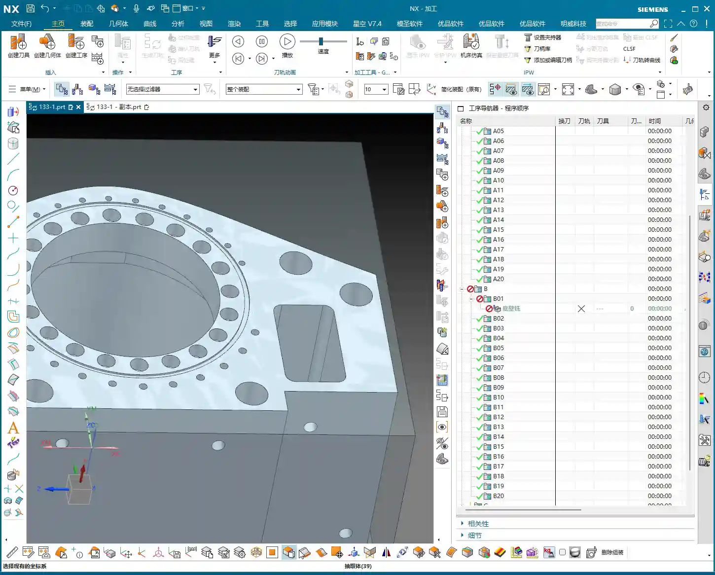
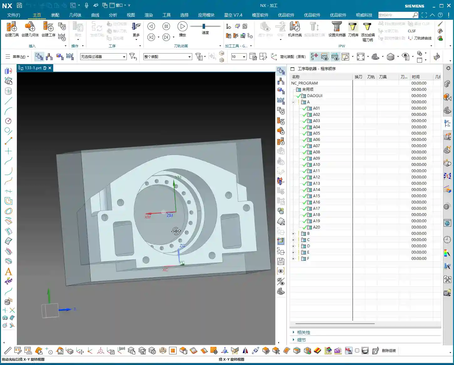
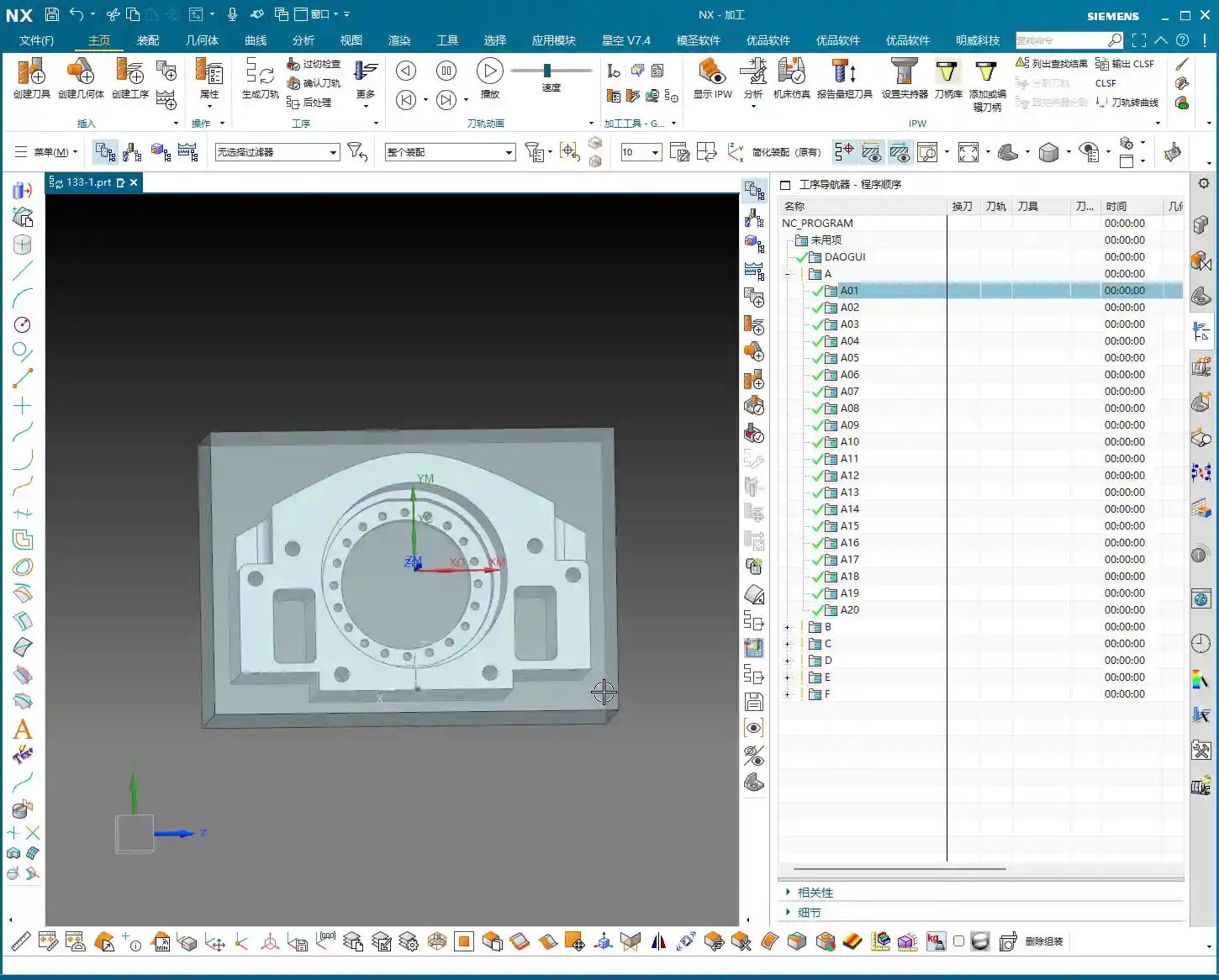
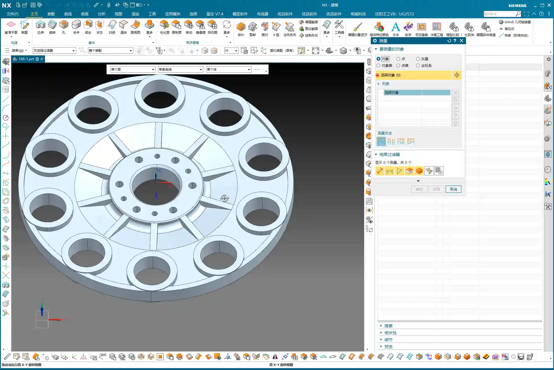
Step Two: Surface Analysis – Discerning the Part’s Geometry
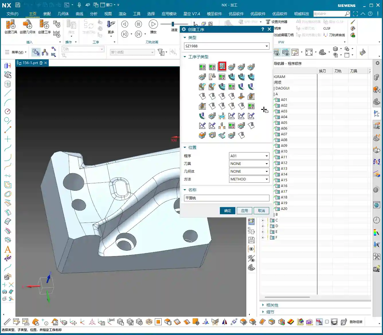
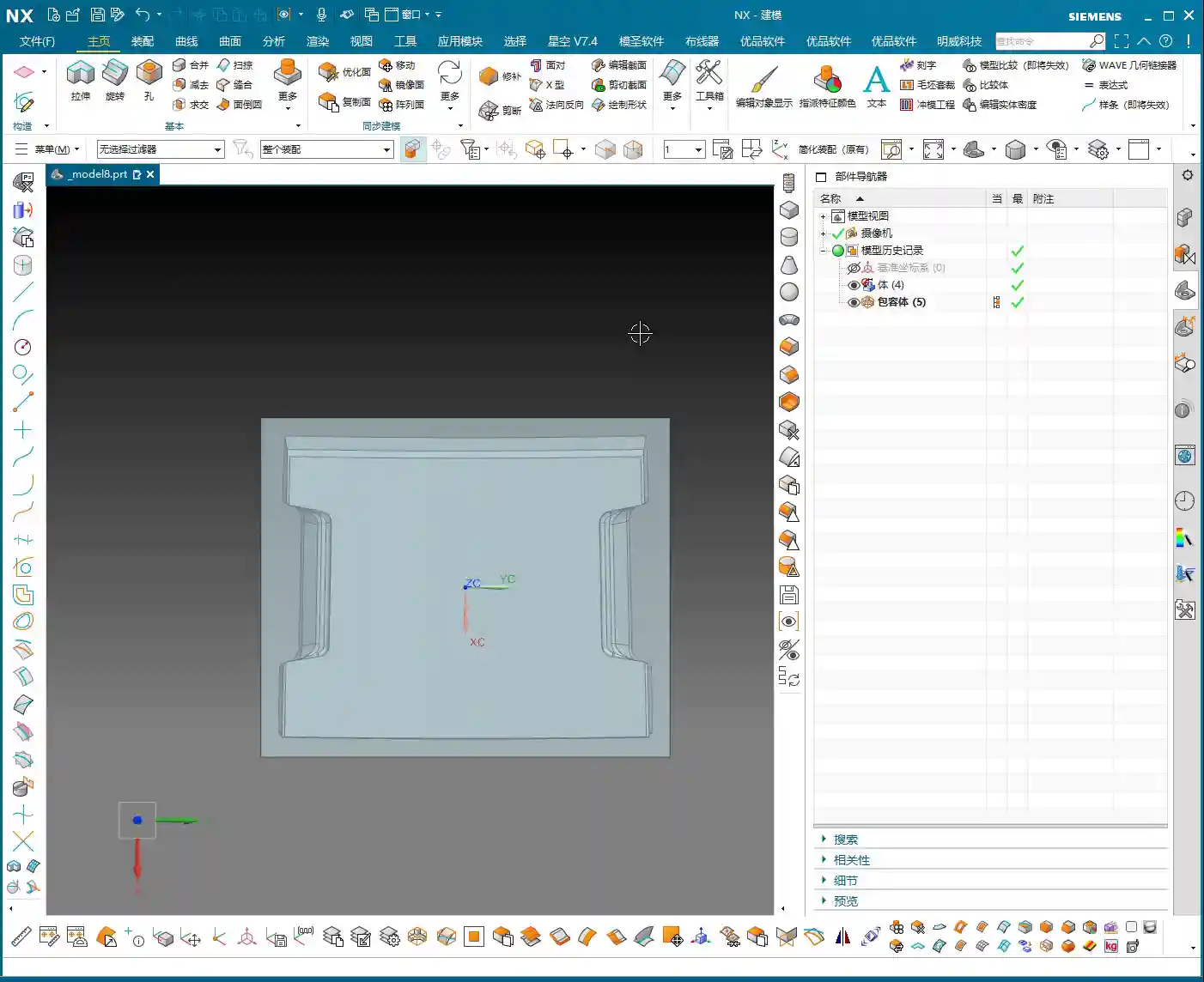
After setting up the WCS, the next step is to analyze the part’s geometry. Just looking at it isn’t enough; Siemens NX has tools, and you need to learn how to use them. I typically use Slope Analysis. This tool allows you to instantly see the part’s underlying structure.
Planar, Inclined, and Curved Surfaces: Tailoring Tool Selection
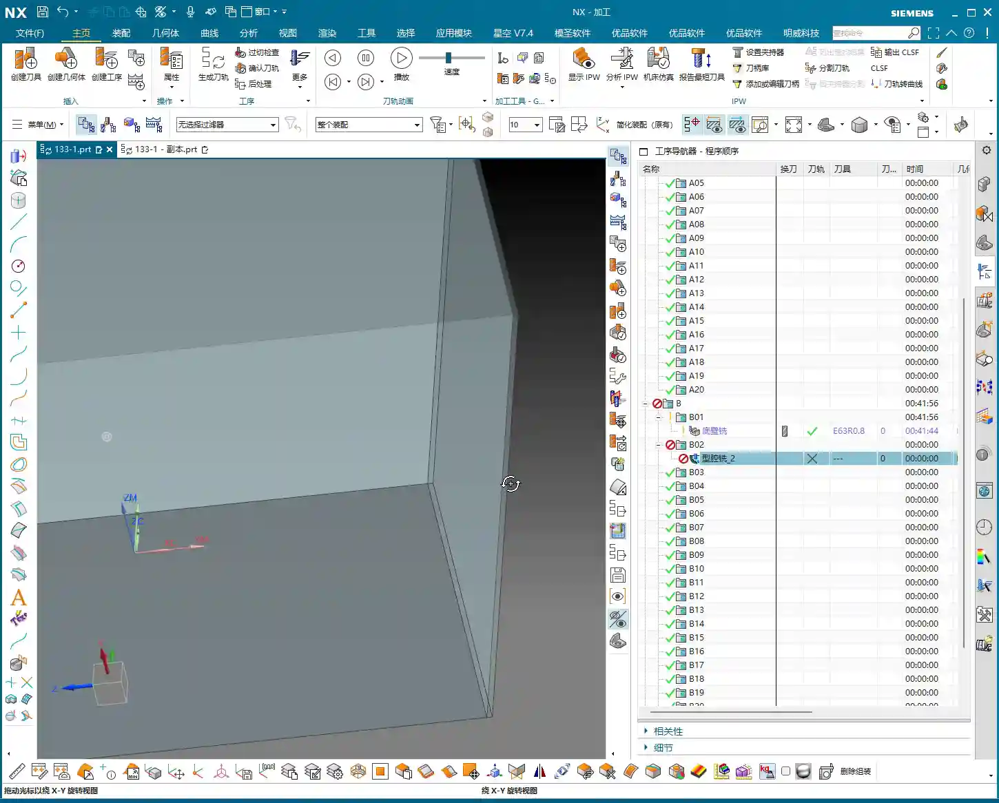
Looking from the top down, most areas are flat, which is straightforward. But when you view it from the side, you’ll notice the part not only has inclined surfaces but also distinct curved surfaces. Especially some root areas are not simple lines or planes. These are the spots prone to challenging tool engagement or difficult-to-machine corners. You must pay close attention to these areas during programming.
Material Properties: Machining Considerations for Aluminum
Let’s assume we’re machining an aluminum alloy part this time. Aluminum is relatively soft, which means longer tool life during machining. Cutting parameters can be set higher. However, you still need to pay attention to chip evacuation and avoiding burrs. If it were titanium alloy or high-temperature nickel-based alloy, it would be an entirely different ballgame. Tools, spindle speed, and feed rates would all need to be redesigned.

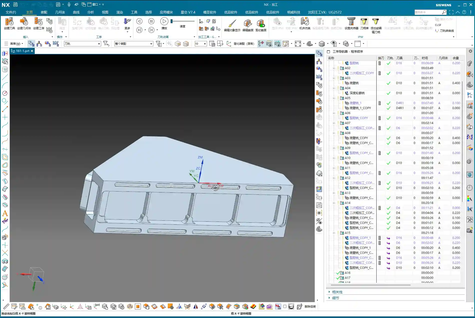
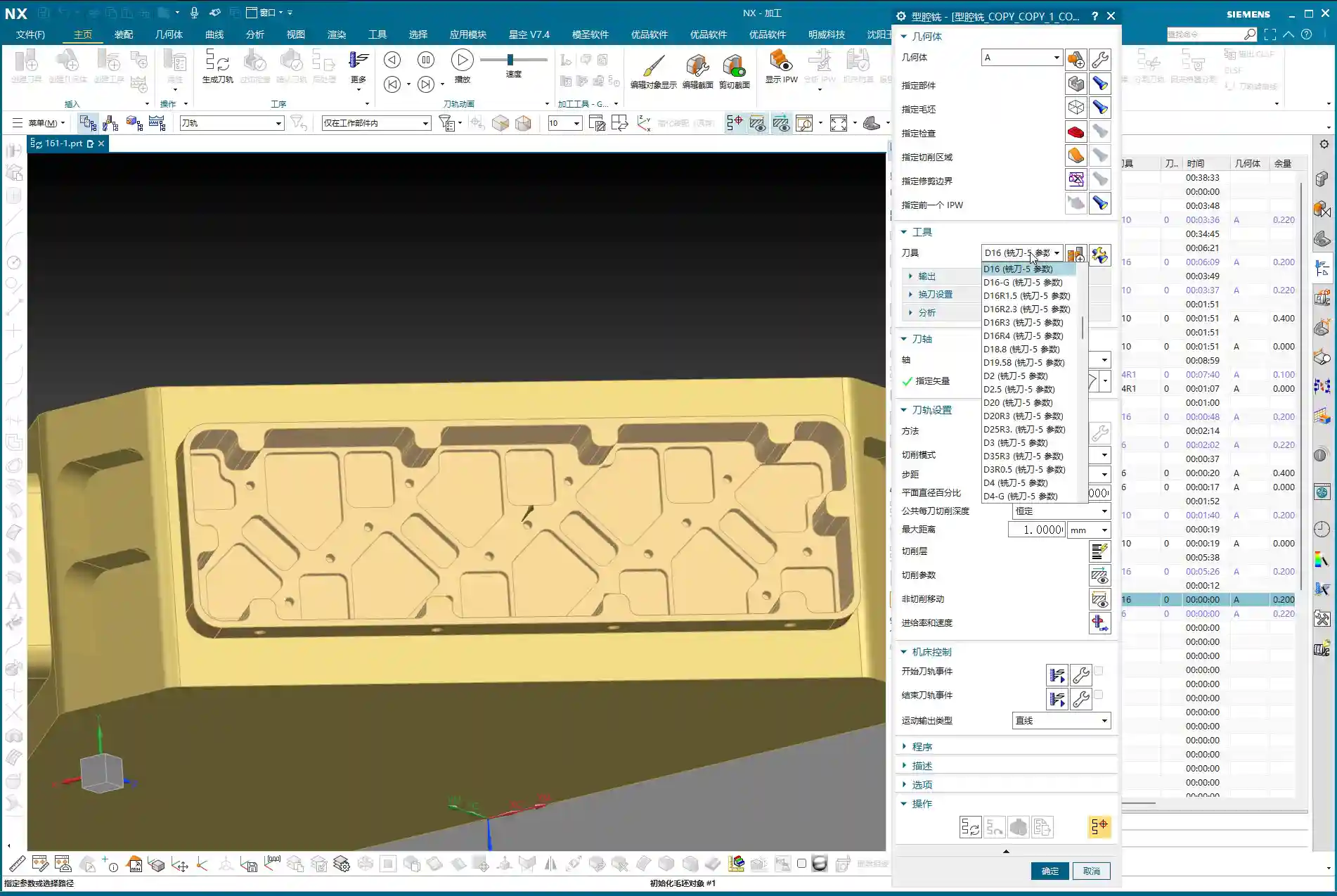
Step Three: Tool Selection and Tool Path Planning – The Cost-Efficiency Trade-off
Tool selection directly determines machining efficiency and final accuracy. It’s like a martial arts master choosing a weapon; whether it’s a good fit makes a world of difference in its power. Don’t just focus on buying cheap; calculate the total cost.
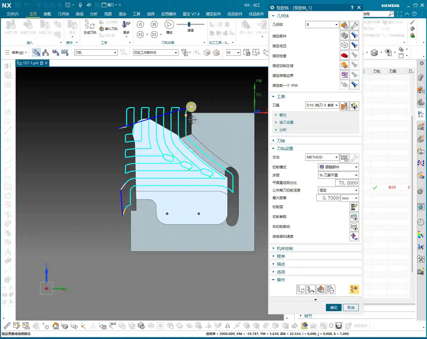
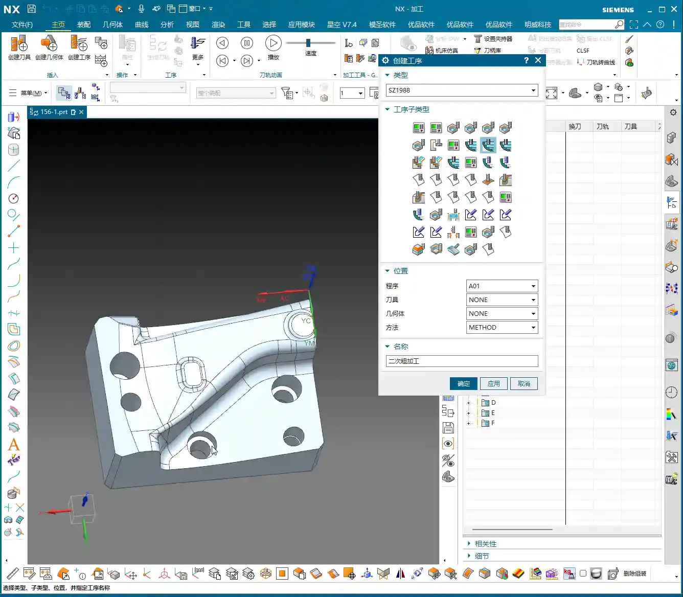
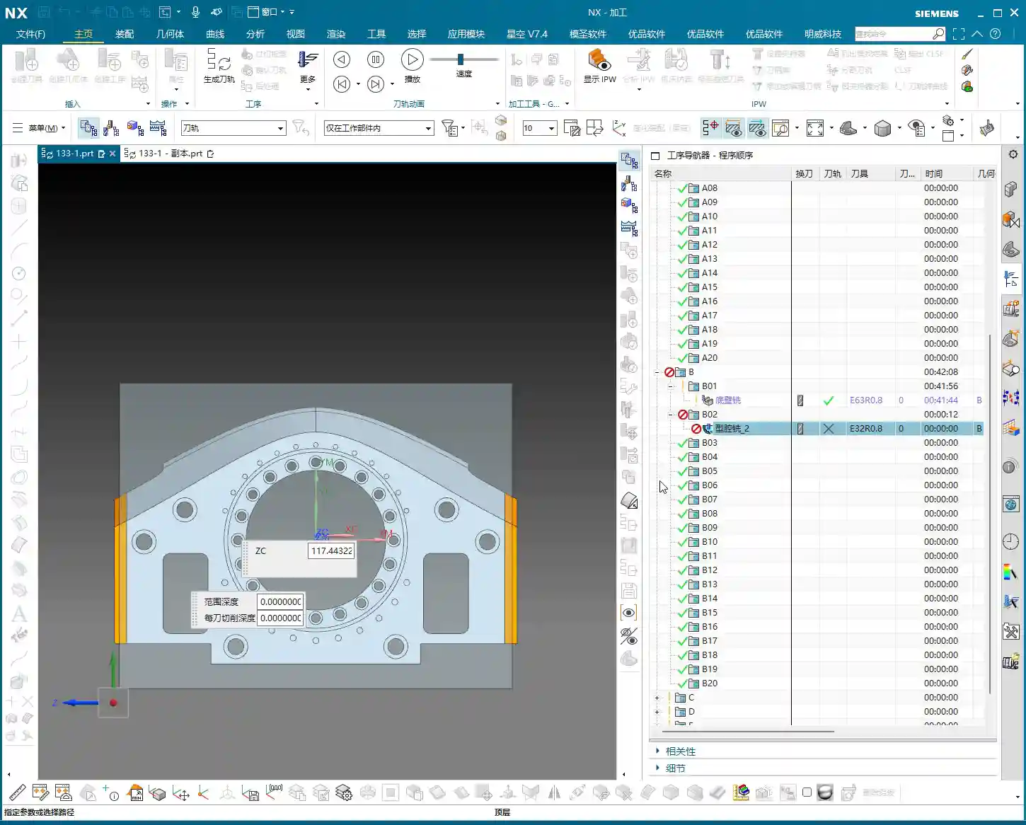
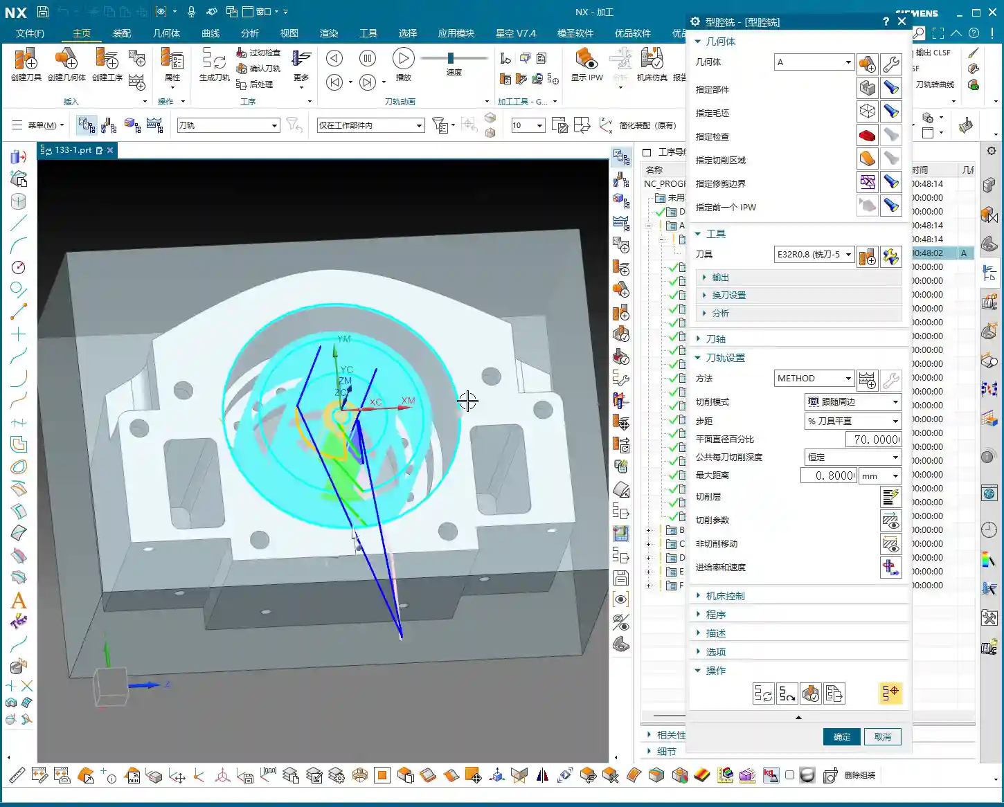
Roughing: Aggressively Removing Excess Material
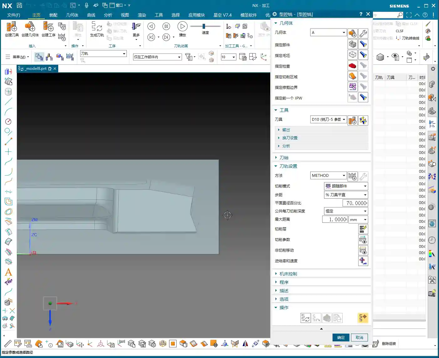
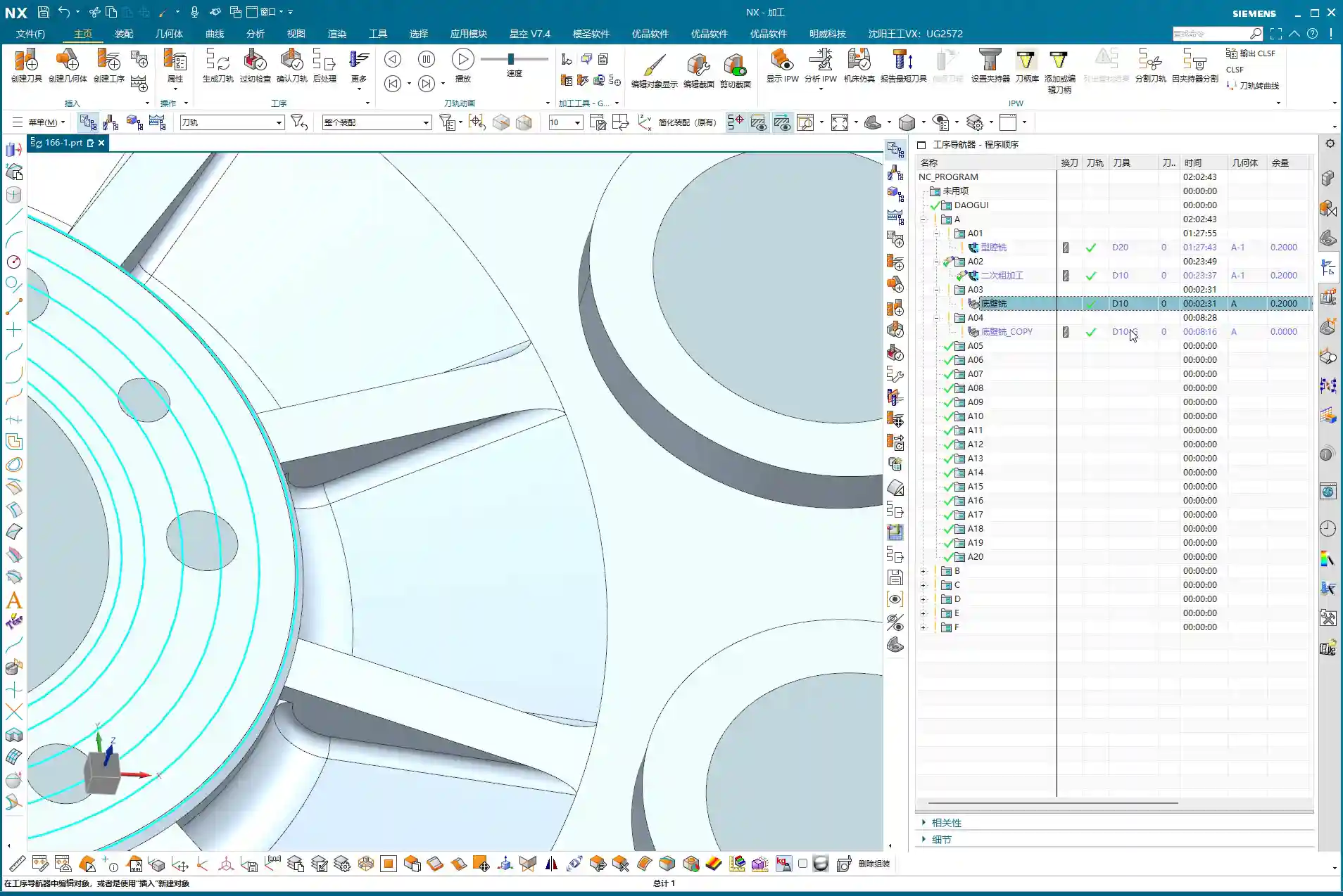
First, let’s look at the roughing pass. Measure the widest machining area, which is about 40 mm. Alright, then, using a 20 mm diameter flat end mill (D20) for Roughing will be most efficient. If the D20 fits without issues, that’s the one. This is what I call “acting first, reporting later”: aggressively remove most of the material, saving time and effort.
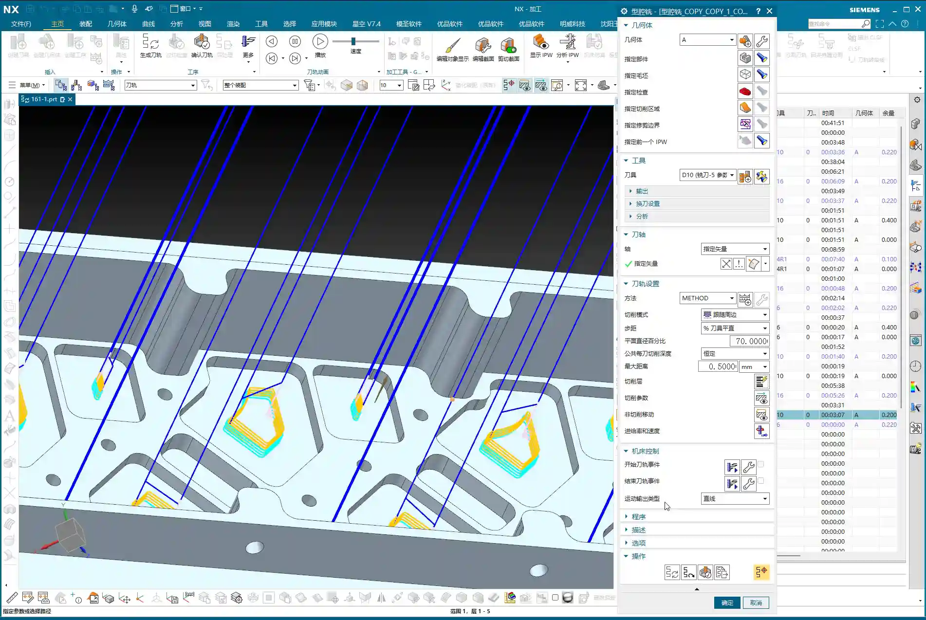
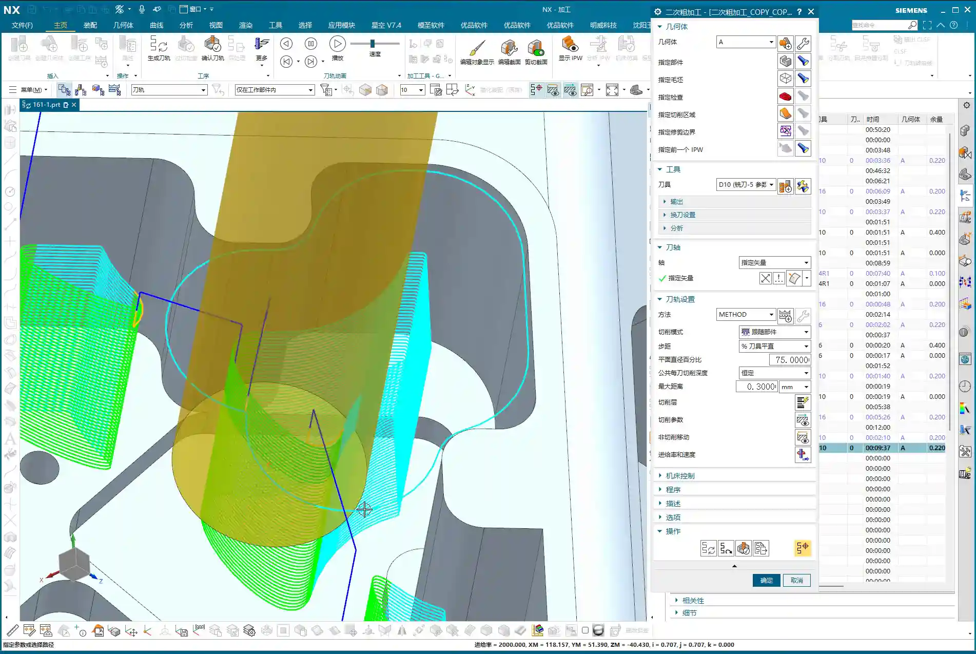
Semi-Roughing and Corner Cleanup: A Step-by-Step Approach for Accuracy
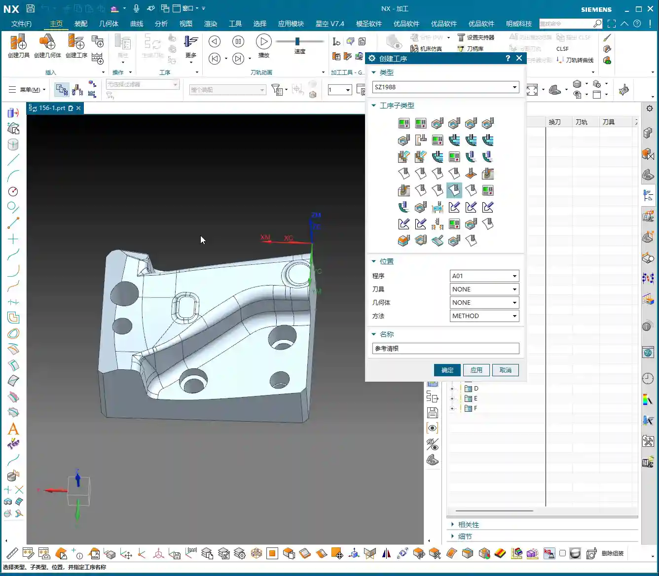
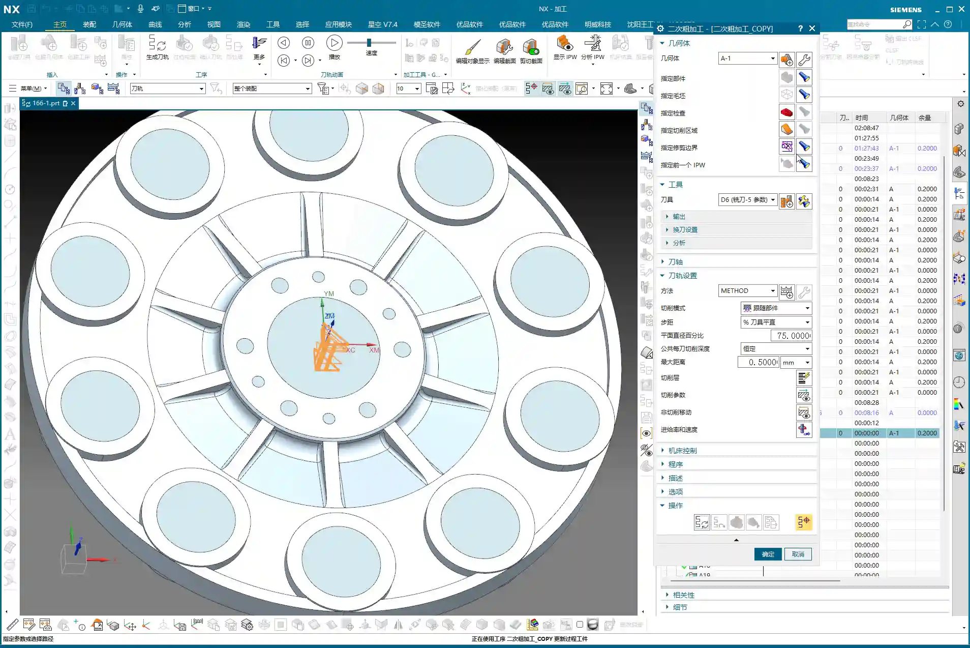
After Roughing, there are some areas where the D20 won’t fit, or the remaining material is not ideal. This is when semi-roughing comes in. Measure those smaller areas, for example, a spot about 10 mm wide, and use a D10 flat end mill. Looking at the backside, there’s a spot only 6 mm wide, so use a D6 flat end mill. By performing Corner Cleanup step by step, you clear out the material left by the larger tool, laying a solid foundation for finishing passes.

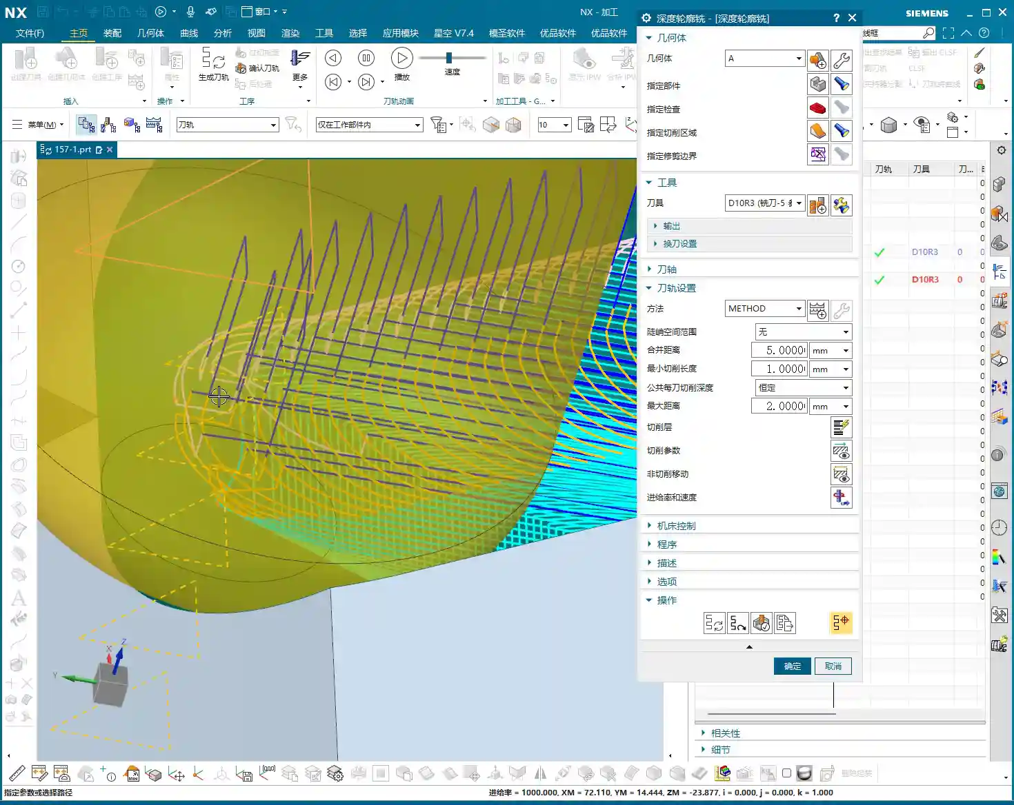
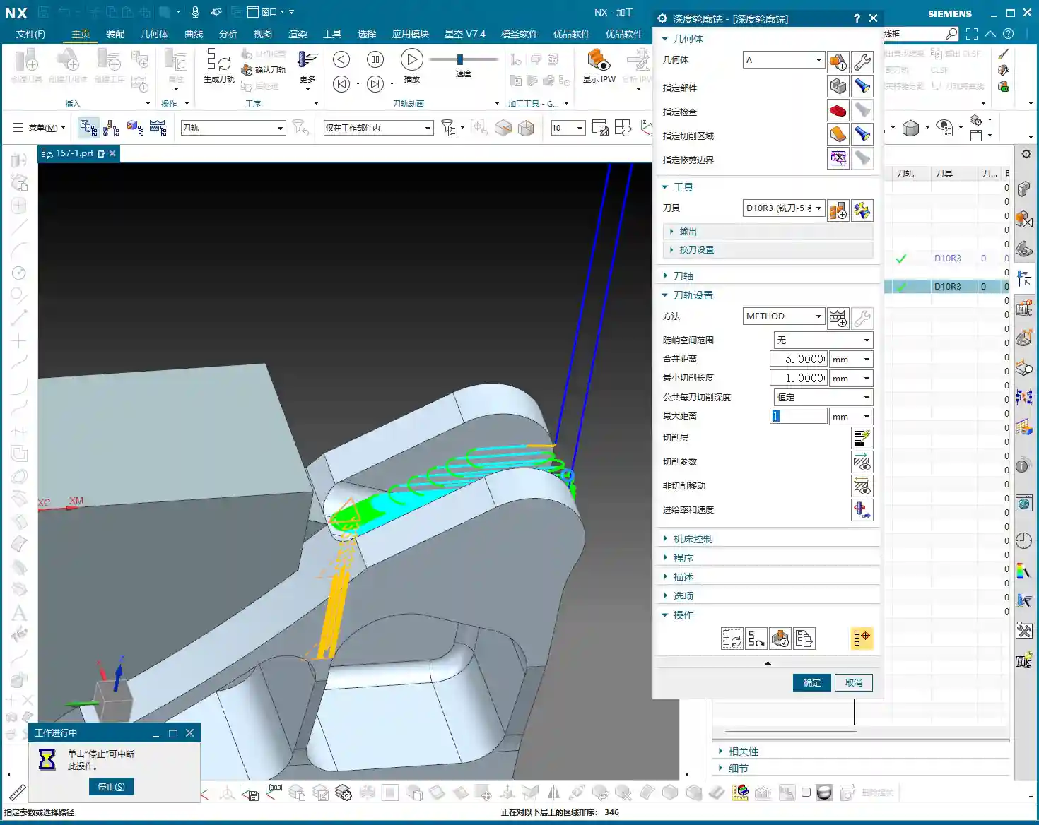
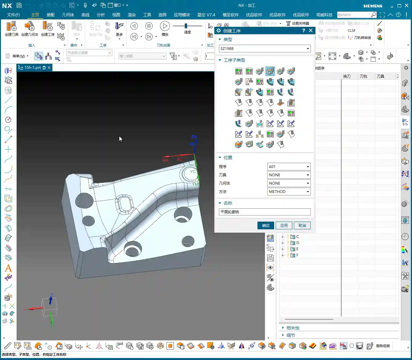
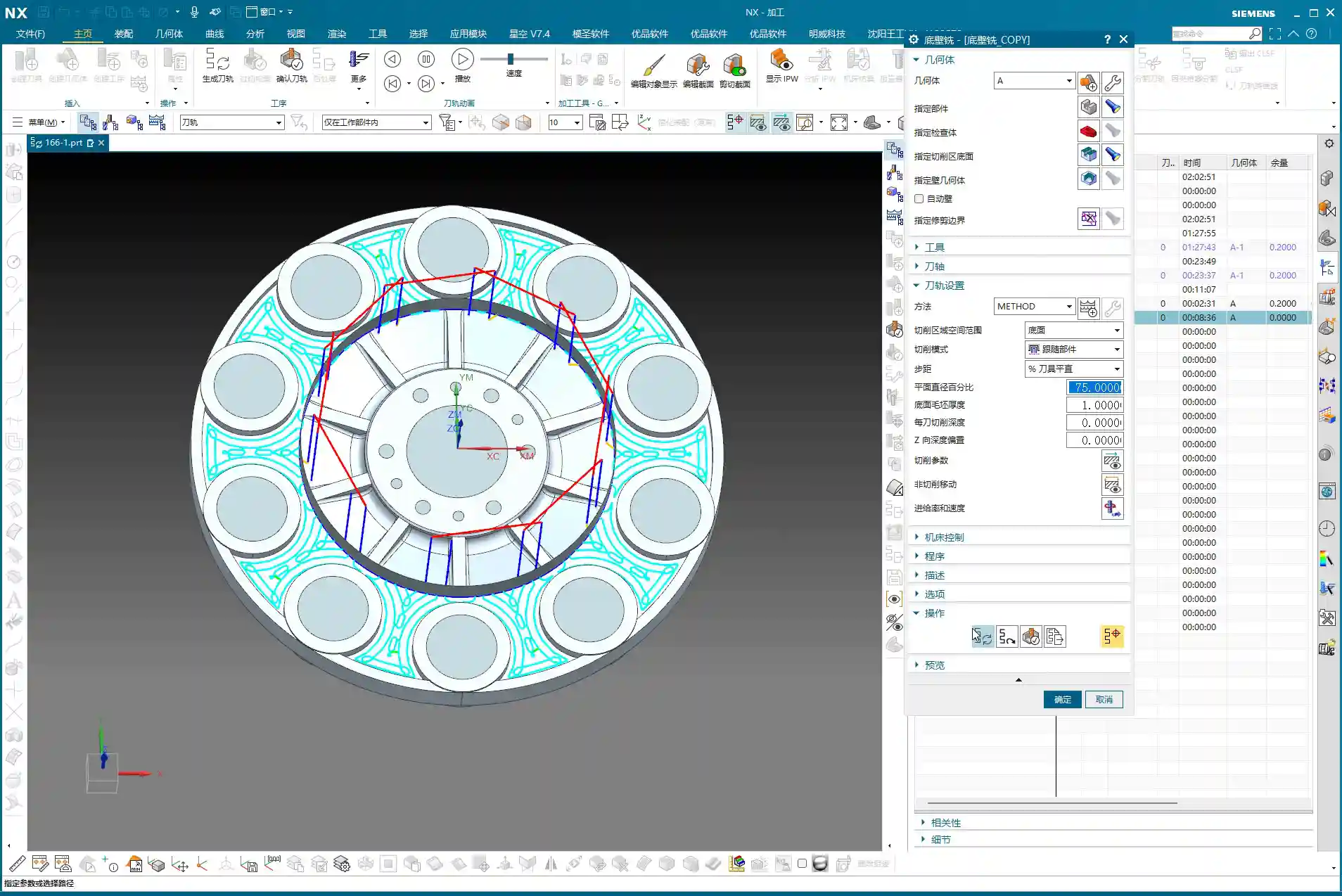
Contour Milling: Achieving a Fine Surface Finish
For those curved and inclined surfaces, a flat end mill alone won’t get the job done. As mentioned earlier, some areas of this part require an R3 fillet. So, directly use a D6R3 ball end mill (meaning a tool with a 3 mm ball nose radius and a total diameter of 6 mm). Use it for Contour Milling these curved surfaces, which will ensure the required surface finish and fillet shape. As for small holes and chamfers, they’re too simple; just use a chamfer tool and a drill, we won’t go into detail about those today.
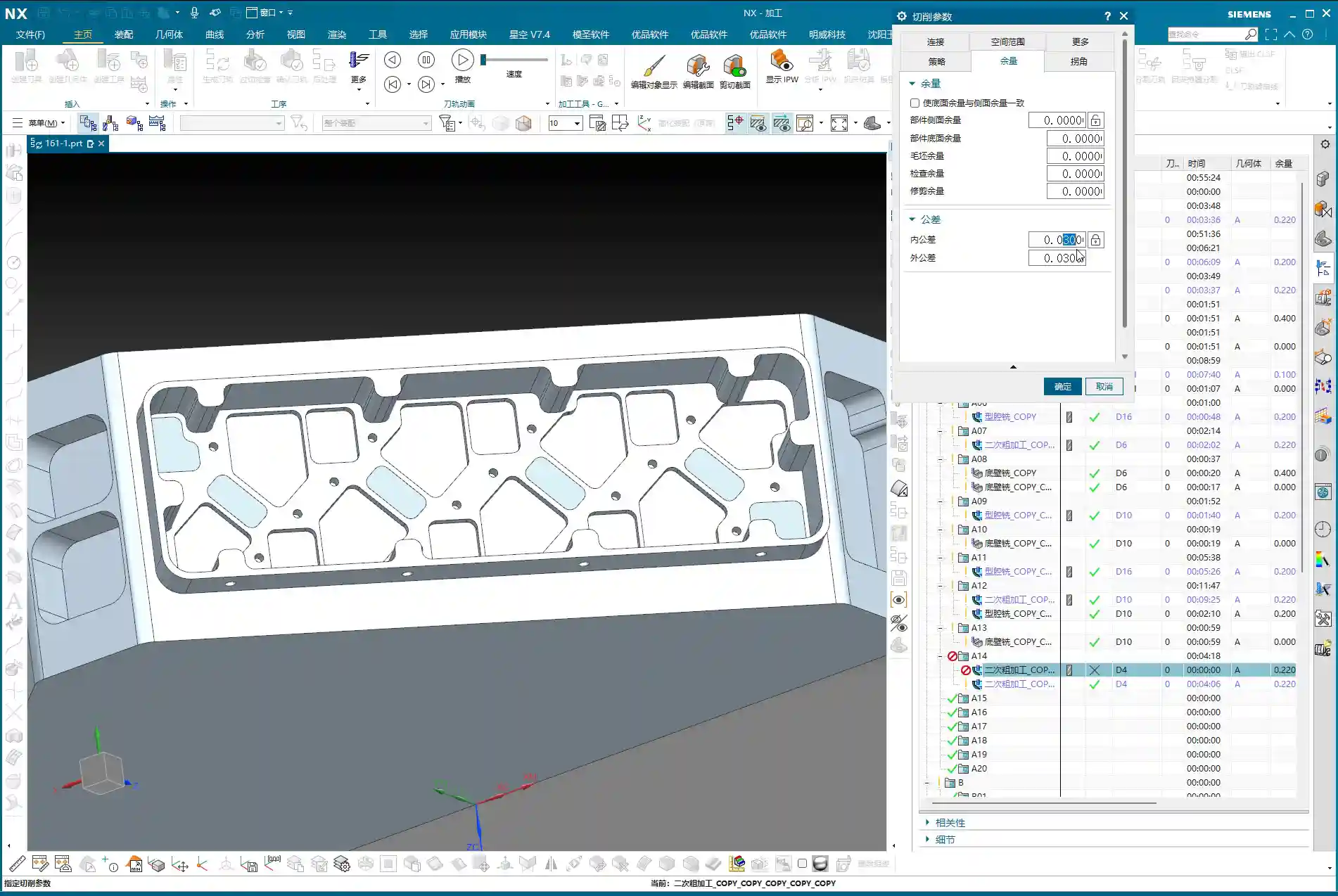
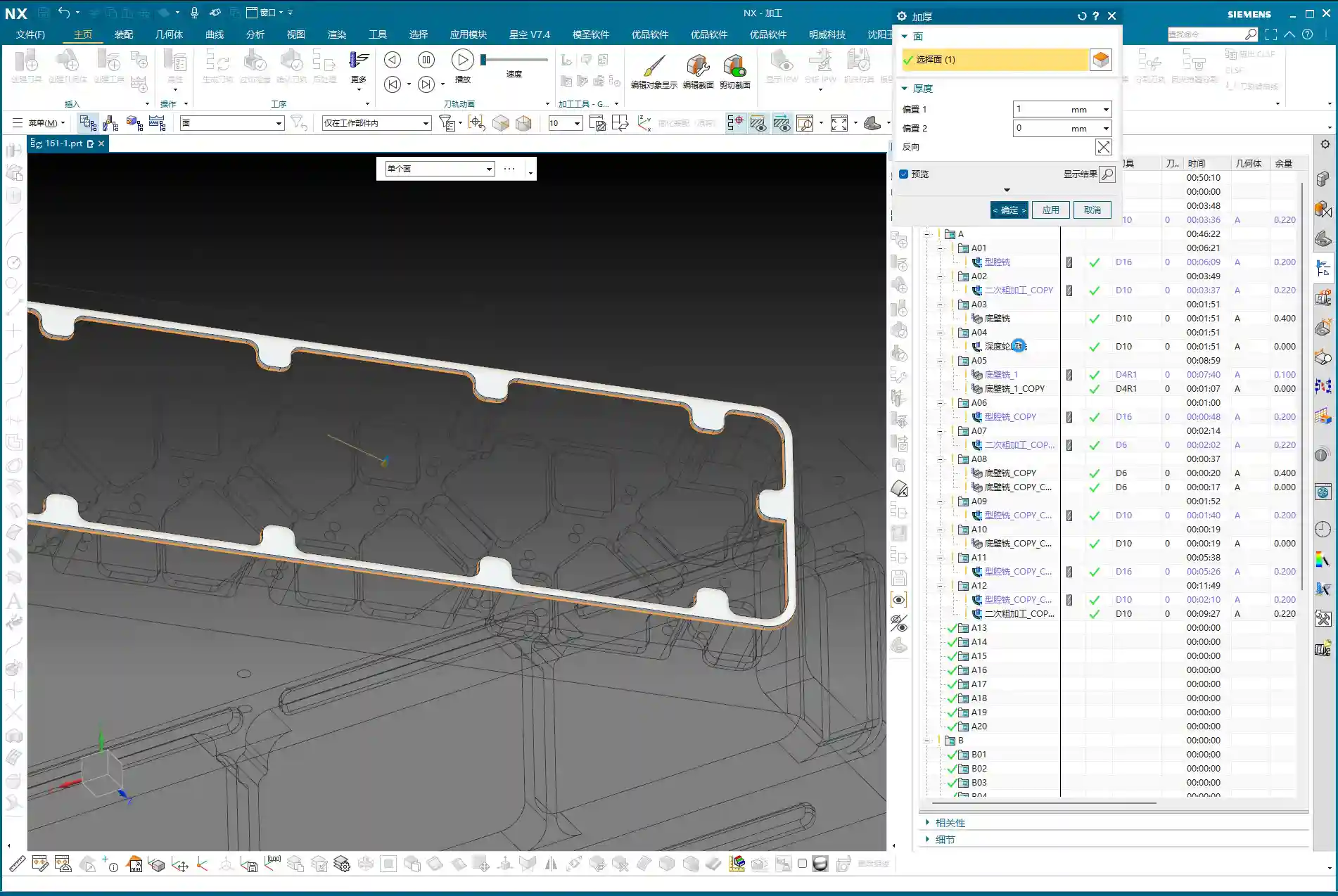
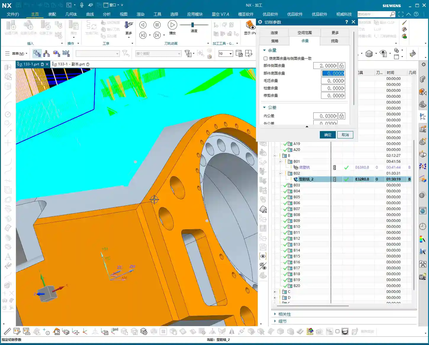
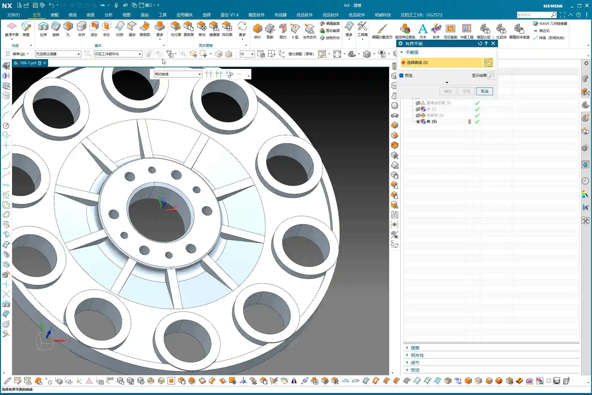
Step Four: Surface Patching and Model Modification – Practical Tips Not Found in Textbooks
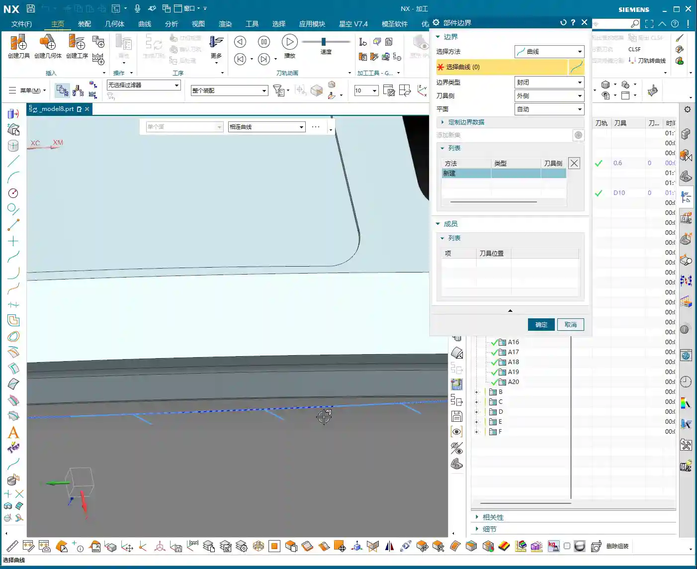
Before programming, a very important step is surface patching. Especially for cast parts or those designed simply, the model often has openings or discontinuous regions. If these areas are not addressed, the software will easily generate errors when calculating tool paths. Use Siemens NX’s “Patch Opening” function to seal up all these areas. Especially for some planar regions, patch them one by one to ensure the model’s integrity.
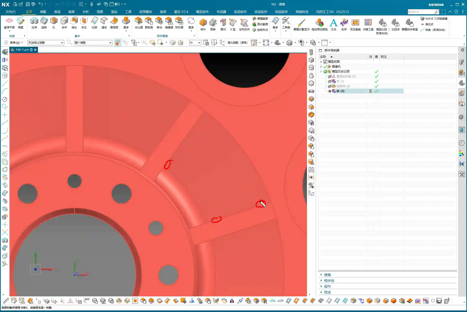
Why Modify the Model? In-Depth Considerations for Fillet (R-corner) Treatment
Here’s something critically important, listen up! There’s one area: if you directly use a D10 tool for semi-roughing and then a D6R3 ball end mill for Contour Milling, you’ll find that the resulting machined surface is not ideal. You’ll see “marks” or “overcuts”. This is because the internal corner left after the D10 tool’s Corner Cleanup is not a standard R3. When the R3 ball end mill then runs, the tool path might conflict. Therefore, you must manually change this area to an R3 fillet within Siemens NX!
If you don’t modify the model, after the D10 passes, that corner will be sharp or irregular. And you expect the D6R3 to “correct” it? Dream on! It will only follow the R3 dictated by the model, resulting in incomplete machining or noticeable tool marks. This kind of “model modification” experience is something gained from countless night shifts, meticulously observing cutting sparks and part burrs, figuring it out bit by bit. Textbooks certainly won’t teach you this!

Residual Material and EDM: An Unavoidable Strategy
Even if your tool selection is meticulous and your tool paths are perfect, some areas, like very deep and narrow root sections, a conventional end mill simply won’t fit, and will inevitably leave triangular residual material. This is normal, don’t get hung up on it. If the customer has extremely high Corner Cleanup requirements for these tight spots, the only solution is to use Electrical Discharge Machining (EDM). Therefore, assessing machining capabilities in advance and communicating effectively with the client is also our responsibility as skilled machinists. Don’t scratch your head in frustration only after the part is scrapped.
Summary: A Guide to Avoiding Pitfalls
Pre-Programming Analysis:
- Blank definition must be accurate: cylindrical, rectangular stock, dimensions, whether to leave material allowance – no step can be wrong.
- Geometric model must be thoroughly analyzed: Utilize Slope Analysis to identify planar, inclined, and curved surfaces, and pinpoint potential machining difficulties and tight corners.
- Fixturing strategy must be clear: Consider rigidity, stability, and ease of flipping to avoid secondary clamping errors.
Siemens NX Operations and Process Key Points:
- Standardize layer management: Blank, part, and fixture each in their designated layers to avoid confusion.
- WCS positioning must be precise: Especially for multi-sided machining, every WCS adjustment must ensure accuracy; this is one source of ±0.005mm level errors.
- Surface patching is a prerequisite before programming: Close up “holes” in the model to provide a clean model for tool path calculation, reducing errors and incorrect tool paths.
- Tool selection should be phased: Large tools for Roughing, medium/small tools for semi-roughing and Corner Cleanup, ball end mills for Contour Milling and Finishing pass. The D20 -> D10/D6 -> D6R3 logic must be clear.
Practical Model Modification and Handling Difficult Areas:
- Model modification is standard practice, especially for fillets (R-corners): If the design doesn’t provide them, but machining requires them, you must decisively “modify the model” to add the fillets. Otherwise, due to tool transition issues between semi-roughing and Finishing pass, tool marks or impressions will be left. This is a critical point in practical machining that is easily overlooked but significantly impacts finished part quality.
- For unmachinable areas, face them head-on: Traditional milling has its limits. For extremely small, deep, or specially shaped tight corners, if high precision is required, directly consider Electrical Discharge Machining (EDM). Don’t force it; that will only damage tools and waste time.
- Don’t just rely on software simulations; observe the cutting sparks: No matter how realistic software simulations are, they cannot replace actual conditions on the machine. Pay close attention to cutting sounds, sparks, and chip evacuation; the machine is “talking” to you, indicating whether your process is reasonable.
Alright, lads, that’s it for this session. This is all experience Master Wang has accumulated over 15 years on the front lines, navigating countless pitfalls. Next time, we’ll get hands-on and program the tool paths for this part step-by-step. Remember, when learning technical skills, you need to use your brain, but more importantly, have eyes that can spot problems and a heart dedicated to solving them!
👤 About the Author:
The author is a veteran CNC machining professional with 15 years of industry experience, specializing in UG NX programming. This article is an original work representing personal practical insights.
⚠️ Copyright Notice: Unauthorized reproduction or distribution without prior communication is strictly prohibited.