📝 Key Takeaways: Master Wang teaches you NX Fixed Contour Milling for non-steep regions, deeply analyzing the “Edit button” parameters. Learn stepover optimization, master the secrets of “On Component” and “First Plane” to avoid toolpath pitfalls, and improve machining efficiency and part accuracy.
Hello everyone, I’m Master Wang. Picking up where we left off, once the program is generated, it’s time for fine-tuning and optimization. Listen closely: in this machining industry, textbook theory is fundamental, but what truly allows you to make a living and produce quality work is the practical know-how and deep understanding of parameters that you won’t find in books.
Choosing Drive Methods and Avoiding Template Traps
As we’ve discussed before, after generating a machining program, some areas will require modification. Generally, we rarely touch the main program itself, as it’s often a very simple framework. So, what exactly do we modify? It’s nothing more than cutting parameters and non-cutting parameters. These two elements are crucial in determining the toolpath and the resulting machining quality.
Fixed Contour Milling: The Essence of Drive Methods
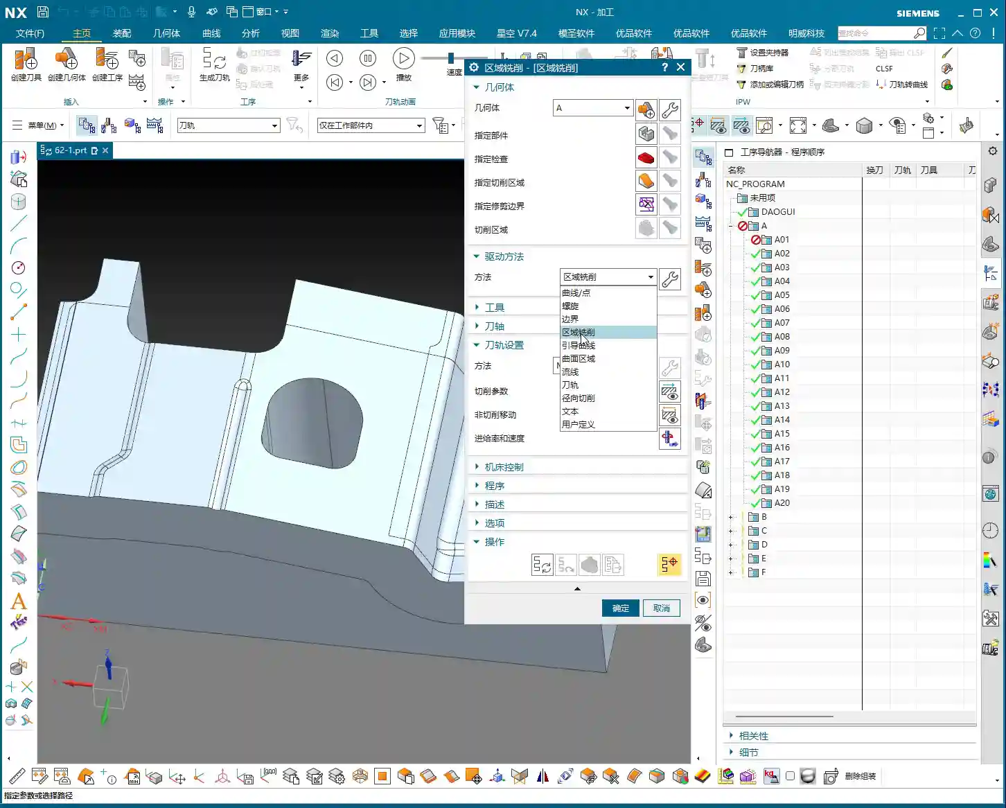
Today, we’ll focus on drive methods. The “Surface Milling” method we’re currently using is actually a type of “Fixed Contour Milling” in NX. Don’t underestimate it; Fixed Contour Milling has many intricacies. Things like “Curve Point,” “Boundary,” “Guide Curves,” and so on—these are all its “sub-methods.”

Template Rules: Do Not Alter Casually
Here’s a major pitfall you need to engrave in your mind: if you’re using the template I set up for you to generate programs, the drive method was already locked in during its creation—for example, it was specifically designed for “Surface Milling.” So, even if you see options in the parameter interface to change to other methods, such as “Curve Point” or “Guide Curves,” never change them arbitrarily!
Why? Because when I created the template, all parameters and logic within it were set up specifically for the “Surface Milling” method. If you change it, it might appear different on the surface, but all the underlying associated parameters will go haywire! At best, the toolpath will look messy; at worst, it will lead to a tool crash and scrap the part, leaving you with nothing but regret. Just remember: during the initial learning phase, if you want to use a specific method, directly select the corresponding operation for that method; don’t mess around with parameters in the dialogue box. Once you gain enough experience, become a master, and fully understand the internal logic of NX, then you can start experimenting on your own. Sharpening the axe doesn’t delay chopping wood; a solid foundation is essential for long-term success.
The ‘Edit’ Button: Your Parameter Adjustment Command Center
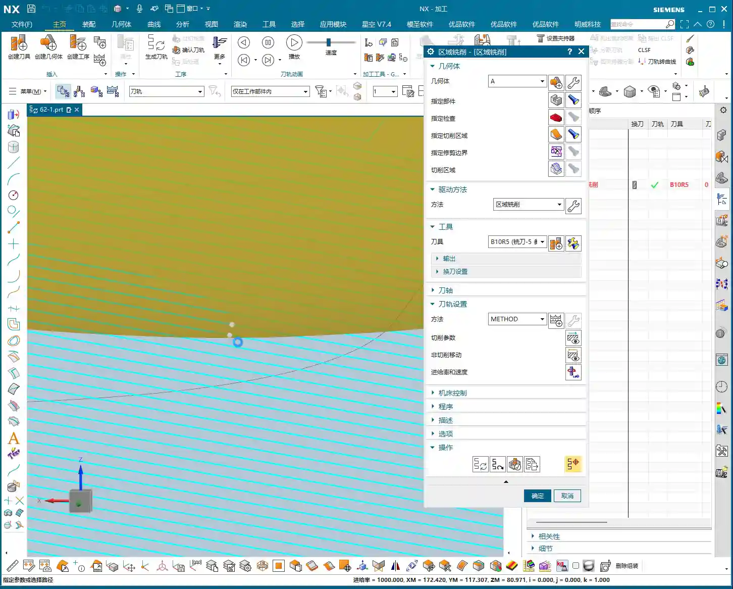
Now, let’s focus on the most important button—that “little white hand” (which is the “Edit” button). In all Fixed Contour Milling operations, whether “Surface Milling” or anything else, ninety percent of the critical parameters we need to change or adjust are located within this ‘Edit’ button. Consider it the “central brain” for machining this program; its every action directly impacts the final part quality and machining efficiency. As for other parameters, either the defaults are fine, or we’ve covered them previously, so I won’t elaborate further here.

The Machining Essence of Non-steep and Steep Regions
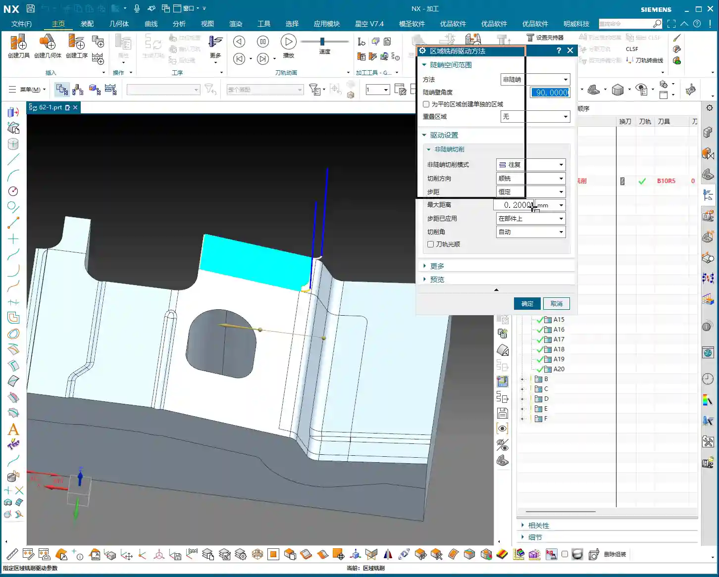
Clicking the ‘Edit’ button, the first thing you’ll see is ‘Method’. Currently, our template defaults to ‘Non-steep’. So, what exactly do ‘Non-steep’ and ‘Steep’ mean?
- Non-steep: Simply put, these are areas with gentle slopes, relatively flat regions. Imagine climbing a mountain where the incline isn’t too severe. In NX, if a surface has a small inclination angle, it’s considered a “Non-steep” region.
- Steep: Conversely, these are areas with very steep slopes, even nearly vertical regions. Like climbing a mountain’s sheer cliff face. In NX, if a surface has a large inclination angle, it falls into the “Steep” region category.
Since we’ve selected the “Non-steep” method, you can temporarily ignore the “Steep Angle” settings, as they are not relevant to our current chosen method. Later, we’ll delve into “Steep and Non-steep” machining and “Steep Machining.” Those are different modes; don’t get them confused for now.
Non-steep Machining Mode and Cutting Direction
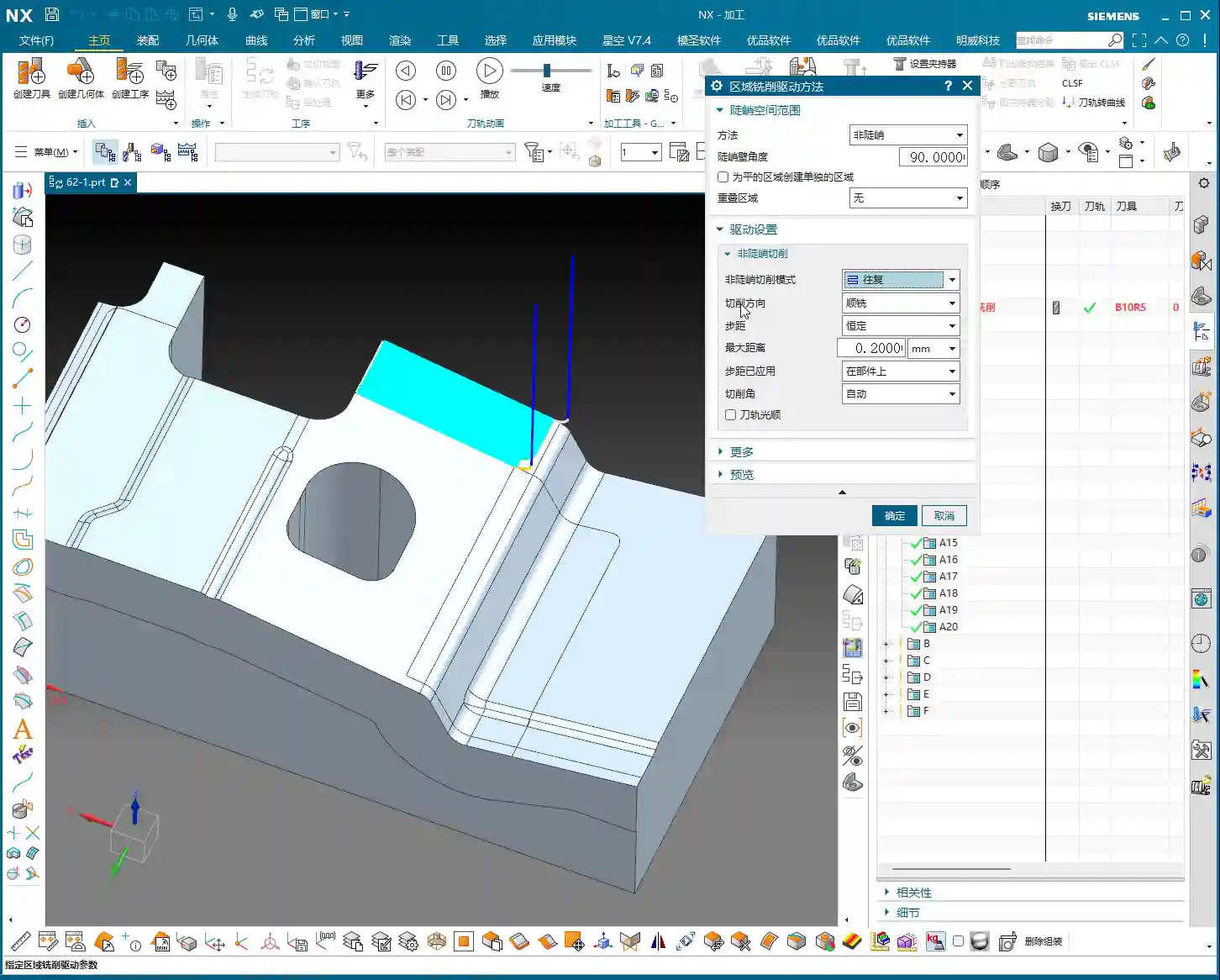
Within “Non-steep Machining Mode,” you’ll find several options: “Zigzag,” “One-way,” “Profile,” “Along Periphery,” and so on. While there seem to be many, only a few are commonly used. These modes determine the tool’s cutting path. We won’t go into detail on each today; let’s primarily discuss cutting direction.
Cutting direction offers two types: “Climb Milling” and “Conventional Milling.” In our “Contour Milling” scenario, truthfully, the difference in results between Climb Milling and Conventional Milling is minimal, unlike in Face Milling where the distinction is much clearer. Therefore, in general, just stick to the default; there’s no need to specifically change it. You won’t see much change if you do, so don’t waste time looking for trouble.


Practical Optimization of Stepover Parameters
Next up is the main event—Stepover. Stepover is the lateral distance the tool moves with each pass; it directly impacts your part’s surface roughness and machining efficiency. Our commonly used stepover type is “Constant” (i.e., fixed stepover).
So, what’s the appropriate setting for “Constant Stepover”? There’s no absolute value; it depends on your material, tooling, part accuracy, and surface finish requirements. However, based on my 15 years of experience, I can give you a practical range:

- For finishing passes, the stepover is generally set between 0.15mm and 0.3mm.
- If extremely high surface finish is required, it might need to be even smaller, for example, 0.1mm or less.
- If you’re roughing or the surface requirements aren’t strict and you just want to quickly remove material, then the stepover can be increased, for example, to 0.4mm or 0.5mm.
Remember this principle: The smaller the stepover, the smoother the machined surface, but the longer the machining time; the larger the stepover, the higher the machining efficiency, but the rougher the surface. You must learn to balance these factors based on the actual situation to find the optimal sweet spot. This is the true skill in machining!
Stepover Application: On Component vs. First Plane
Finally, let’s talk about the two options in “Stepover Application”: “On Component” and “First Plane”. At first glance, these two options might seem similar, but in practice, especially when machining complex surfaces, their impact can be significant!

- On Component: This is the default setting in NX and the one we use most frequently. It means the tool’s stepover is measured and applied directly on the actual surface of the part. The tool will follow the part’s surface as closely as possible, ensuring consistent stepover within the actual cutting area. In this mode, the toolpath adjusts according to the surface’s geometry, striving for uniform machining across the entire part surface.
- First Plane: This option is quite interesting. When you select “First Plane,” NX will prompt you to choose a plane, and then it will project the tool’s stepover onto this plane for calculation, rather than calculating it directly on the part’s surface. This can lead to a problem: on inclined or undulating surfaces, the actual stepover during cutting might deviate from your set value, potentially resulting in uneven toolpaths.
For instance: imagine you’re machining a wavy surface. If you use “On Component,” the tool will follow the undulations of the wave uniformly. But if you use “First Plane” and select a horizontal plane, the tool’s stepover will be uniform in the horizontal direction, but at the crests and troughs of the wave, the actual cutting distance might increase or decrease. While sometimes the toolpath differences aren’t obvious to the naked eye, these discrepancies will become apparent at the part’s edges, corners, or specific geometric features, affecting the final surface quality and potentially causing tool marks.
Therefore, my recommendation is that unless there are specific requirements, generally use “On Component”. If you absolutely must use “First Plane,” then you must very carefully inspect the toolpath, and even verify it through test cuts. Don’t just rely on the software’s flawless simulation; you need to observe the cutting sparks and feel the part’s surface—those are the real-world tests!


Summary: Pitfall Avoidance Guide
- Templates are paramount, do not alter methods: When using preset templates, do not arbitrarily change the drive method within the parameter dialogue box. During initial learning, directly select the operation corresponding to your desired method to prevent internal parameter conflicts.
- The ‘Edit’ button is key: All detailed parameters for Fixed Contour Milling are located within the “Edit” button. Mastering it means mastering the key to toolpath optimization.
- Non-steep is fundamental: Understand the characteristics of “Non-steep” regions. It is our default method for processing most part surfaces.
- Stepover requires fine-tuning: Based on part accuracy and surface roughness requirements, set the stepover appropriately (recommended 0.15mm-0.3mm), balancing machining efficiency and quality.
- ‘On Component’ vs. ‘First Plane’: The devil is in the details: Prioritize “On Component” to ensure the toolpath closely follows the actual surface. If using “First Plane,” thoroughly inspect the toolpath’s actual effect in complex geometric areas to avoid machining defects.
- Practical experience is paramount: Theoretical knowledge is foundational, but hands-on operation, observing cutting sparks, and inspecting part surface quality are the keys to improving your skills and solving real-world problems.
👤 About the Author:
The author is a veteran CNC machining professional with 15 years of industry experience, specializing in UG NX programming. This article is an original work representing personal practical insights.
⚠️ Copyright Notice: Unauthorized reproduction or distribution without prior communication is strictly prohibited.
Leave a Reply