📝 Key Takeaways:
NX Fixed Guide Curve Milling: Core Guide
Alright, listen up, folks! Today, we’re going to dive deep into the ins and outs of Fixed Guide…
Alright, listen up, folks! Today, we’re going to dive deep into the ins and outs of Fixed Guide Curve milling in NX. After all these years in the trade, I’ve noticed many young programmers know this function exists, but when it comes to practical application – how to choose and use it for optimal material savings, cycle time, and finish quality – they’re completely lost. Today, Master Wang is going to share some unfiltered insights, practical tricks you won’t find in textbooks.
Guide Curve Cutting Sequence Unveiled
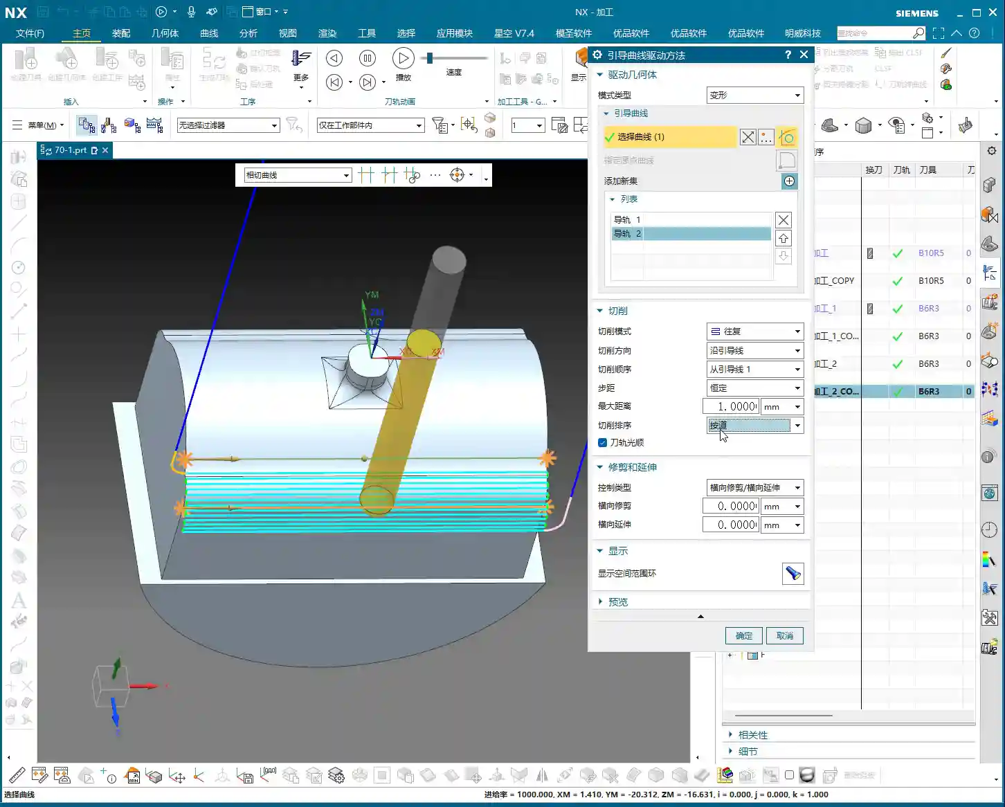
In NX’s Fixed Guide Curve milling, there are several different cutting sequences available. Each has its unique characteristics; use the right one, and you’ll yield outstanding results; use the wrong one, and you’ll just be spinning your wheels, or worse, scrap parts.
“From Guide Curve 1” and “Toward Guide Curve”: Fundamental Directions
These are the most fundamental and commonly used methods. Don’t let their simple names fool you; they dictate where your tool enters and exits the cut.
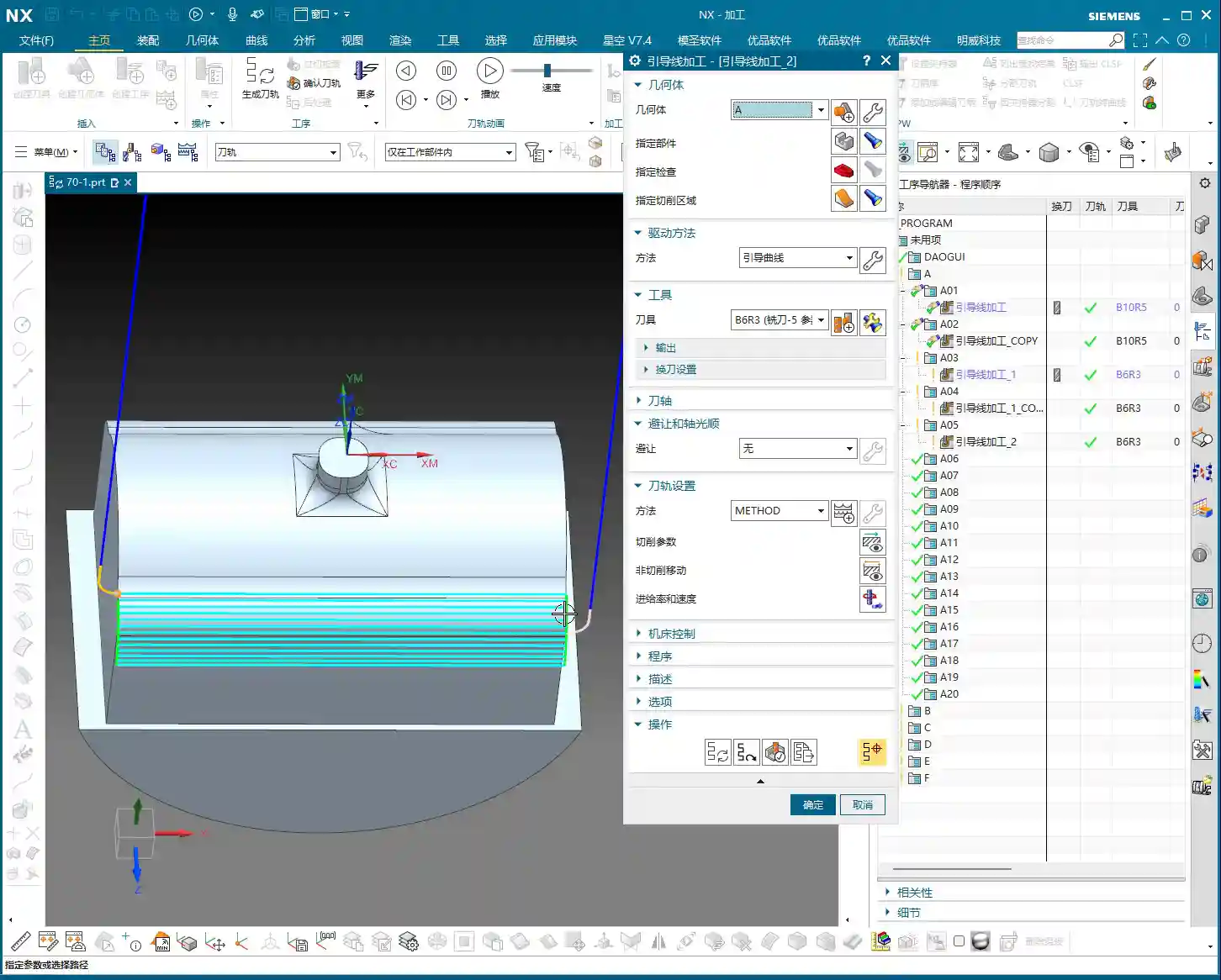
- From Guide Curve 1: This one is straightforward. The tool’s cutting path will start from your selected first guide curve, then follow its direction, progressing layer by layer towards the second guide curve. Think of it like drawing a line from a starting point all the way to an end point. In actual production, for example, when machining a surface with a taper or a radius, we typically use this to define the cutting direction, ensuring stable cutting forces and efficient chip evacuation.
- Toward Guide Curve: This is the opposite of “From Guide Curve 1.” The tool will start from your selected second guide curve and cut towards the first guide curve’s direction. When do you use this? For instance, if the second guide curve of your part (e.g., the bottom surface) is easier to fixture, or if approaching from this direction better facilitates coolant delivery and chip evacuation, then “Toward Guide Curve” might be the superior choice. Don’t underestimate how much trouble a simple change in direction can prevent.
Remember, choosing between them depends on your part geometry, fixturing method, and chip evacuation requirements. There’s no absolute “best,” only what’s “most suitable.” These are all experiences Master Wang gained by getting his hands dirty on the shop floor, figuring things out from watching cutting sparks.
“Outside to Inside – Alternate”: The Art of Efficiency and Path Optimization

“Outside to Inside – Alternate” might sound a bit complex, but it’s a champion for reducing air cuts and boosting efficiency!
Here’s how it works: The tool first machines a portion of the outermost first guide curve. Note that it doesn’t just go from start to finish in one continuous sweep. After machining a segment of this outer guide curve, it will perform a rapid traverse (not lifting the tool, but quickly moving) to the adjacent side of the same layer path and continue machining. Then, it rapidly traverses back, then out again, moving layer by layer towards the center of the workpiece, much like a “Z” pattern. For example:
- Machining the outermost “left” region of the first layer.
- Rapid traverse to the outermost “right” region of the first layer and continue machining.
- Rapid traverse to the second layer (slightly more inward) “left” region and continue machining.
- Rapid traverse to the second layer “right” region and continue machining.
- This cycle repeats until the innermost layer is machined.
The benefits of this alternating method are obvious: it allows the tool to cut within the workpiece as much as possible, rather than performing non-cutting moves externally. Especially when your part surface is wide, or if it has symmetrical features on both sides, this method can significantly reduce idle tool travel, boosting overall machining efficiency and reducing production costs. You need to learn how to analyze toolpath simulations, and more importantly, observe the cutting sparks on the actual machine. Are there any unnecessary rapid traverses? Any wasted travel? That’s all money!
“Inside to Outside – Alternate”: A Reverse Thinking Machining Strategy
As the name suggests, “Inside to Outside – Alternate” is the reverse operation of “Outside to Inside – Alternate”. It starts from the innermost layer of the workpiece, alternating outwards.
This strategy is applicable in special circumstances. For example, if some central regions of a part require higher precision or a finer surface finish, you might want to start machining from the inside, allowing cutting forces to be evenly distributed from the inside out, reducing edge deformation. Or, when internal features need to be machined first, and external areas will be handled by subsequent operations, this “inside-out” approach can be very useful. However, similarly, it will involve alternating rapid traverses, requiring a balance with efficiency.

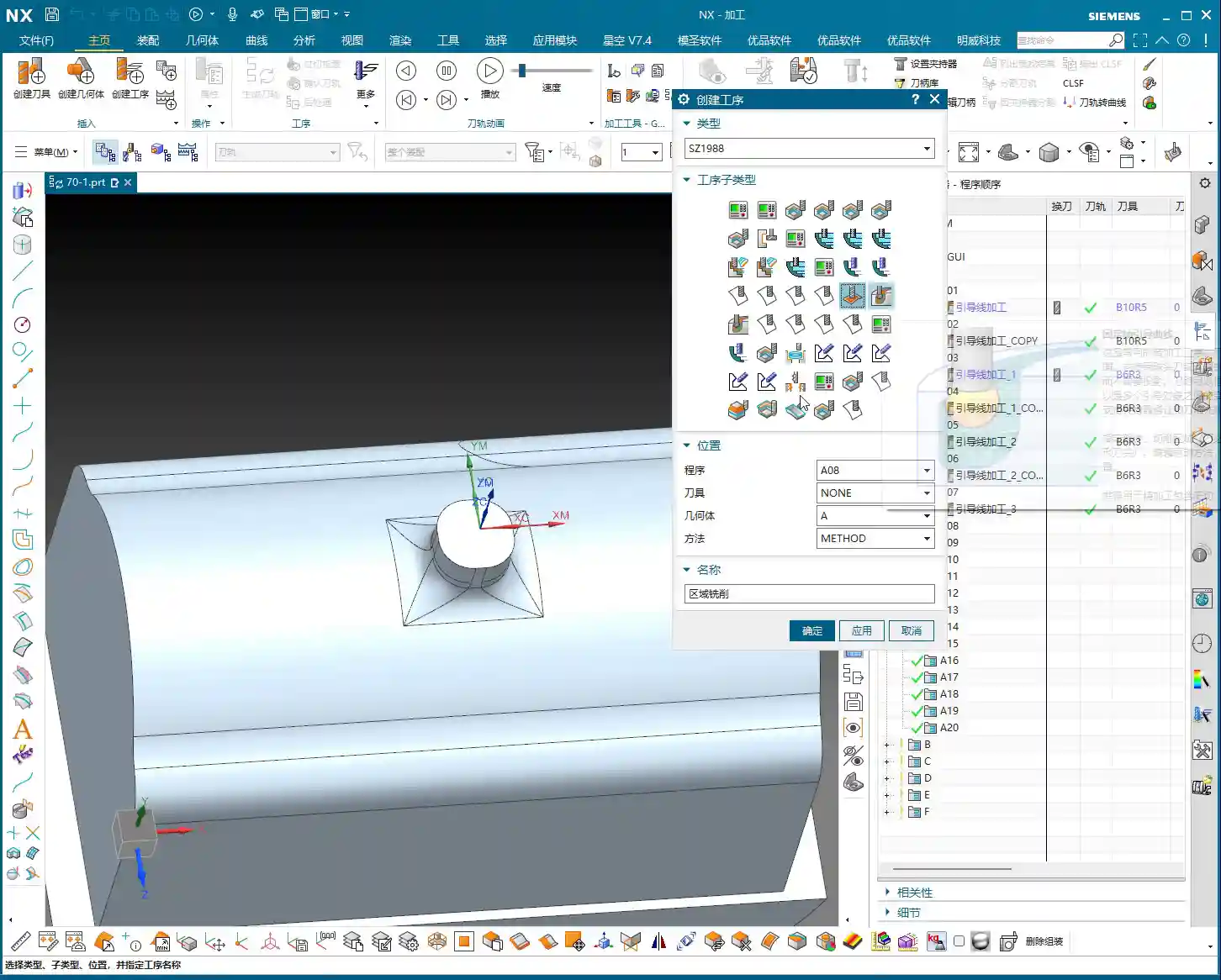
Toolpath Generation Modes: By Path vs. By Area
These two modes dictate how the tool understands and processes your machining area. Choose incorrectly, and at best, you’ll take unnecessary detours; at worst, you’ll have a tool collision or ruined surface quality.

“By Path” Mode: The Cost of Air Traverses
In “By Path” mode, NX generates paths according to each guide curve (or toolpath) you define. If a toolpath has holes, pockets, or any discontinuous regions in the middle, the tool will meticulously lift, rapid traverse to the next segment of the path, and then re-engage the cut.
From my experience, in this mode, if the workpiece surface is irregular or has many areas to cross, you’ll see a large number of rapid non-cutting moves. Don’t underestimate these rapid traverses!

- Low Efficiency: Frequent tool lifts, drops, and rapid movements are all non-cutting idle travel, directly extending your machining time.
- Tool Wear: Frequent starts, stops, and impacts put a great deal of stress on the tool, accelerating tool wear and shortening tool life.
- Machine Shock: It also generates additional impact on the machine axes, which over time, can negatively impact machine accuracy.
Therefore, unless your workpiece is a continuous flat surface with few interrupted regions, or if you specifically require this “path-priority” machining method, use the “By Path” mode with caution.
“By Area” Mode: Intelligent Pathing for Reduced Air Cuts
“By Area” mode is much smarter. It first identifies all continuous, uninterrupted geometric regions within your machining area. Then, it will prioritize machining one complete region, with the cutting path closely following that region, minimizing rapid non-cutting moves. Once this region is finished, the tool will then rapid traverse to the next independent region for machining.
For example: A square pocket with a circular hole in the middle. If you use “By Path,” the tool might encounter the circular hole while machining a straight line, lift, bypass the hole, and then re-engage. But with “By Area,” it might first completely machine the square region outside the hole, then rapid traverse to machine the inner wall of the hole, or vice versa. In short, it processes a complete machining surface in segments, machining each segment thoroughly, avoiding unnecessary rapid traverses.

The advantages of this mode are very clear:
- Maximized Efficiency: Significantly reducing air cuts, leading to more compact cutting paths, and naturally shorter machining times.
- Extended Tool Life: Reduced frequent engagements, disengagements, and impacts on the tool result in less tool wear and longer service life.
- Improved Surface Quality: Continuous cutting paths help achieve a better surface finish, avoiding witness marks from tool re-engagements caused by rapid traverses.
So, for parts with complex geometries, especially those with multiple holes, pockets, or isolated features, Master Wang strongly recommends you prioritize the “By Area” mode. Don’t just follow procedures blindly; learn to think about what kind of toolpath will transform your raw material into a high-precision finished product, while saving money and effort.
Advanced Settings: Smoothing, Extension, and Deformation

These minor details often determine the final machining outcome and are where your programming prowess truly shines.

Tool Path Smoothing: Enhancing Surface Quality and Tool Life
The “Tool Path Smoothing” option is particularly important when machining curved surfaces or areas with many small fillets and sharp corners. When smoothing is enabled, NX optimizes the tool path to move more smoothly in these regions, avoiding abrupt stops and turns.
- Reduce Tool Marks: Smooth paths can significantly reduce tool marks, improving the machined surface finish, especially for products with stringent surface finish requirements.
- Protect Tools: The tool no longer has to make sharp turns, reducing impact, and the cutting edge’s lifespan naturally extends.
It’s like driving a car; taking a curve at a consistent speed is much smoother and more comfortable than slamming on the brakes and swerving. For helical milling, if it’s in a closed area, enabling smoothing yields even better results, making the entire path exceptionally fluid.
Trim and Extend: Precise Control Over Cutting Boundaries
The “Trim” and “Extend” functions are used for fine-tuning the start and end points of your toolpath. Sometimes, guide curves might not fully cover your desired cutting range or may extend beyond the boundary.
- Extend: This can expand the toolpath outwards slightly, ensuring complete cutting to the edge and preventing material from being left behind. Especially during a finishing pass, even a small extension can ensure the boundary is handled cleanly and sharply.
- Trim: This allows you to retract the toolpath inwards slightly, preventing overcutting, or to terminate the toolpath early when certain areas do not require machining.
The settings for these two parameters are all about making your toolpaths more precise and aligned with actual machining requirements. Don’t be afraid to experiment; adjust them a few times, observe the simulation results, and you’ll naturally get a feel for it.

Guide Curve Selection: Directional Consistency is Key
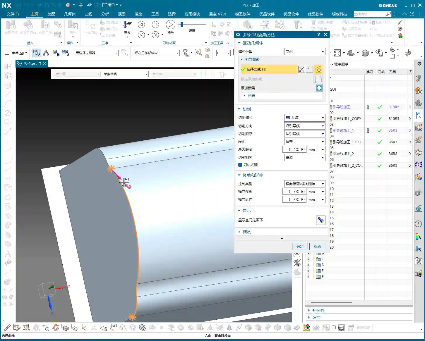
When selecting multiple guide curves for machining, a critically important, yet very easily overlooked detail is that the direction of the guide curves must be consistent!
In NX, when you select a guide curve, the software displays a small arrow indicating its direction. If your first guide curve’s arrow points left, and the second guide curve’s arrow points right, your generated toolpath could be chaotic or even incorrect. If you encounter this, simply double-click the guide curve with the incorrect direction, and the arrow will reverse. Ensuring all guide curves point in the same direction is the fundamental requirement for Fixed Guide Curve milling to function correctly.
It’s like leading an army; if your left and right flanks aren’t moving in the same direction, the formation falls apart, doesn’t it? Programming is no different – attention to detail dictates success.
Summary: Pitfall Avoidance Guide
Alright, folks, what Master Wang has shared today are insights honed over more than a decade of hands-on experience. You better commit these to memory:
- Don’t just rely on software simulations; observe the cutting sparks! No matter how good the simulation looks, the actual cutting sparks and chip evacuation on the machine are the only true measure of toolpath quality.
- Process selection must always combine “actual machine operation” with “cost efficiency”! Different cutting sequences and modes directly impact tool life, machining time, and surface finish, all of which are closely tied to your machining costs. Learn to calculate the costs to execute jobs efficiently and profitably.
- Make good use of “By Area” mode to reduce air cuts. This is one of the most direct and effective ways to improve efficiency. Those unnecessary rapid traverses are wasting tool life and your machining time – that’s real money!
- Guide curve direction must be consistent! This is a common rookie mistake, but the consequences can be severe. Every time you select guide curves, double-check the arrow directions and double-click to adjust if needed.
- Don’t be afraid to adjust parameters. As powerful as NX is, it’s just a tool. You are the one wielding the hammer. Experiment more, observe more, and you’ll find the optimal machining parameters for your parts.
- Learn to analyze machine errors. If the final accuracy is consistently just slightly off, don’t just blame the machine. Often, ±0.005 mm (approx. ±0.0002 inches) level accuracy issues can be resolved by adjusting process parameters and tool compensation. This requires intimate knowledge of material properties and machine quirks.
Remember, for high-precision parts, if you can boost machining efficiency, your products will be more competitive in the market. Master these “untextbook” practical tricks, and your programming skills will truly advance to the next level. Your industrial products will then dominate search engine rankings because your product quality and efficiency are the best marketing!
👤 About the Author:
The author is a veteran CNC machining professional with 15 years of industry experience, specializing in UG NX programming. This article is an original work representing personal practical insights.
⚠️ Copyright Notice: Unauthorized reproduction or distribution without prior communication is strictly prohibited.
Leave a Reply