Tag: Toolpath Optimization

  • Siemens NX Secondary Roughing Programming Masterclass: Master Wang Teaches High-Efficiency Corner Cl

    📝 Key Takeaways:

    NX Secondary Roughing: Master Wang’s Practical Techniques

    Opening: Lingering Issues from the Last Program

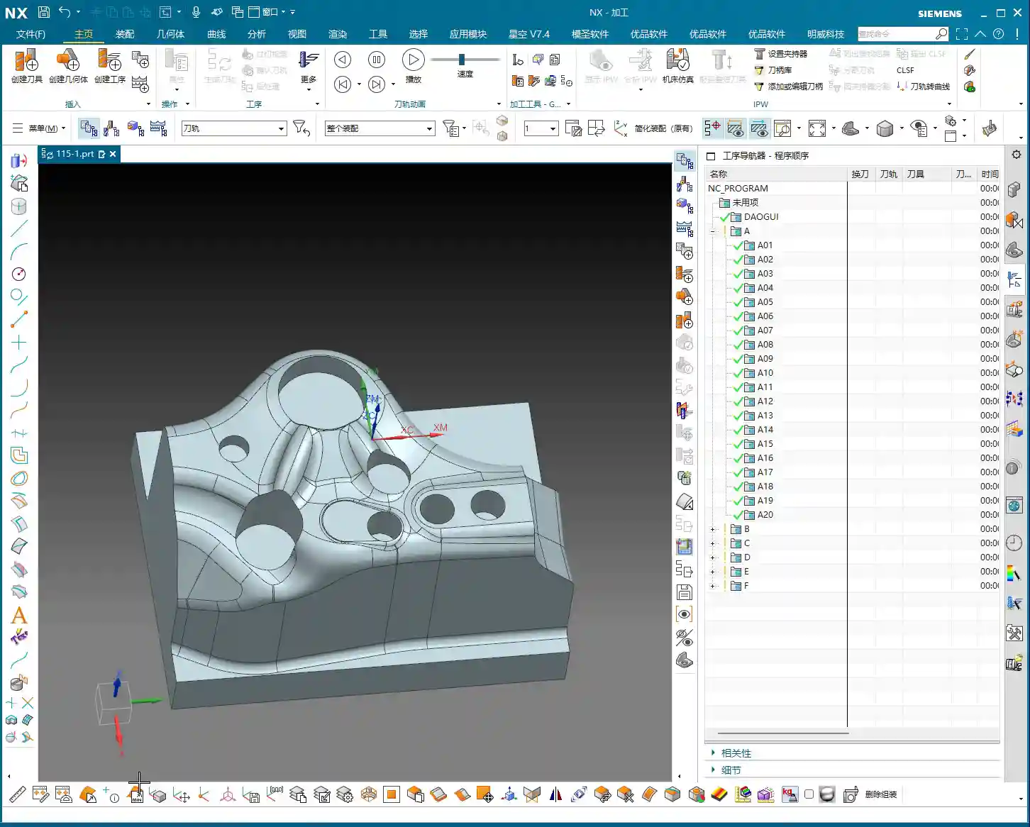
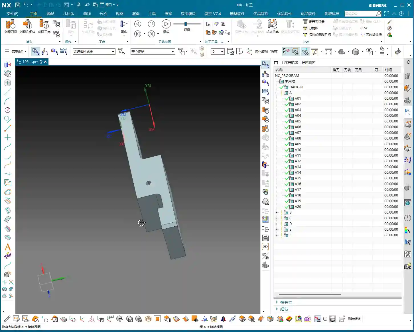
    Hello everyone, I’m Master Wang. In our last session, we finished programming the roughing operations for the first side. However, in some areas, the program ran slowly, and the computer lagged a bit. In the workshop, time is money, and a slow program means lost production! So today, we need to address these lingering issues, especially those “unmachined” areas, which are regions that weren’t fully cleaned up.

    Checking and Addressing Residual Stock

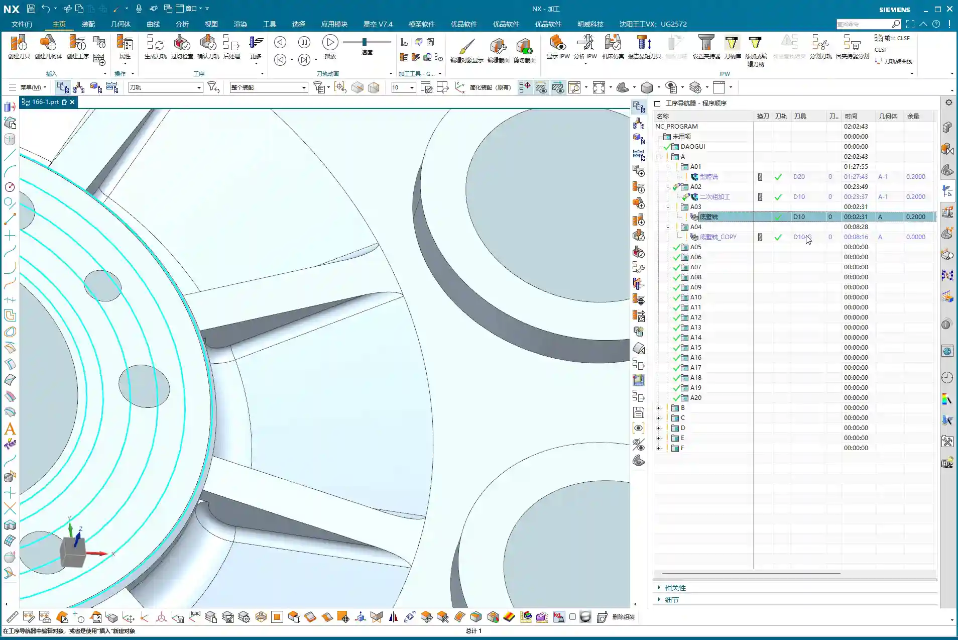
    Alright, let’s go back one step and quickly check which areas weren’t fully milled. Listen up: don’t just focus on the large flat surfaces. The real problem spots, where the tool is likely to engage heavily and cause issues, are often the small corners and grooves. I’ve noticed several areas that were “skipped” or “missed,” leaving behind a bit of residual stock. Some areas, especially on the side walls, still look like they have “remnants.”

    • Problem Areas: Found several spots, particularly edges and corners, where small amounts of stock remained after the previous program, looking “unmachined.”
    • Solution Approach: A “Corner Cleanup” operation is needed to remove this residual stock, preparing the part for subsequent finishing passes.

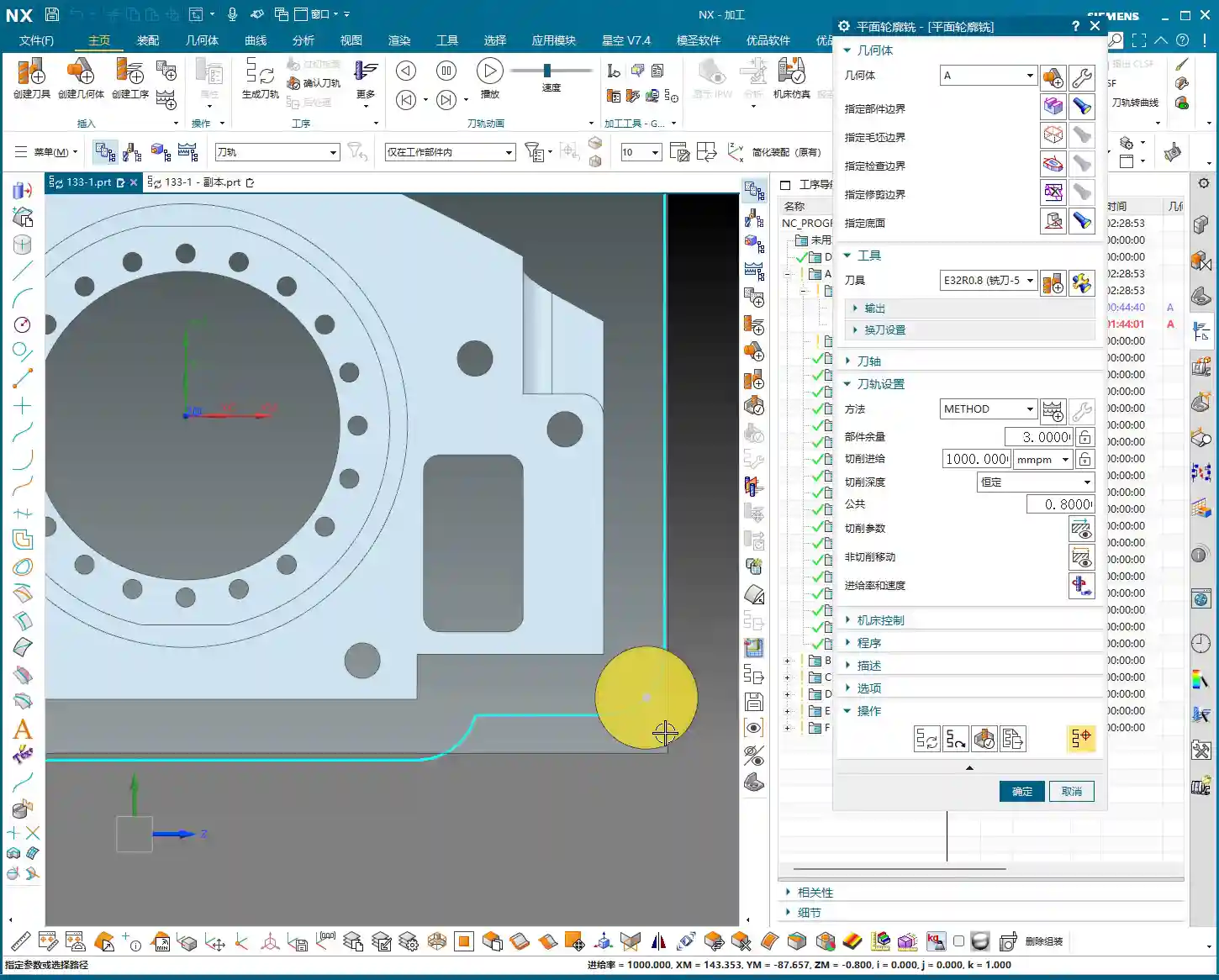
    First Corner Cleanup: Addressing Residuals on the First Side

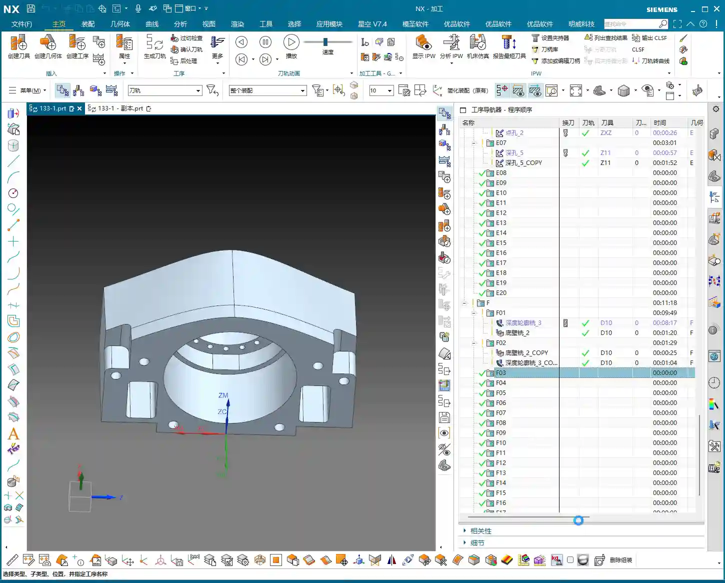
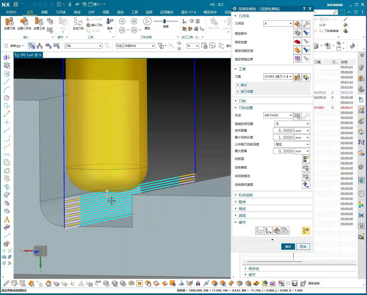
    For this residual stock, we can simply copy an existing program and make a few parameter adjustments. This is the most efficient method and minimizes errors.

    Program Duplication and Parameter Adjustment

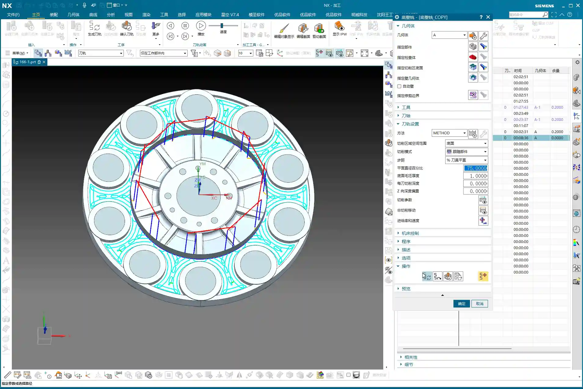
    I’ll directly copy one of our previous programs. Remember, after copying, the first thing you must do is check several key parameters:

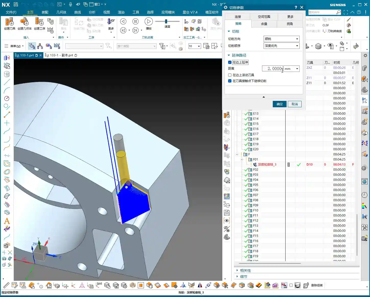
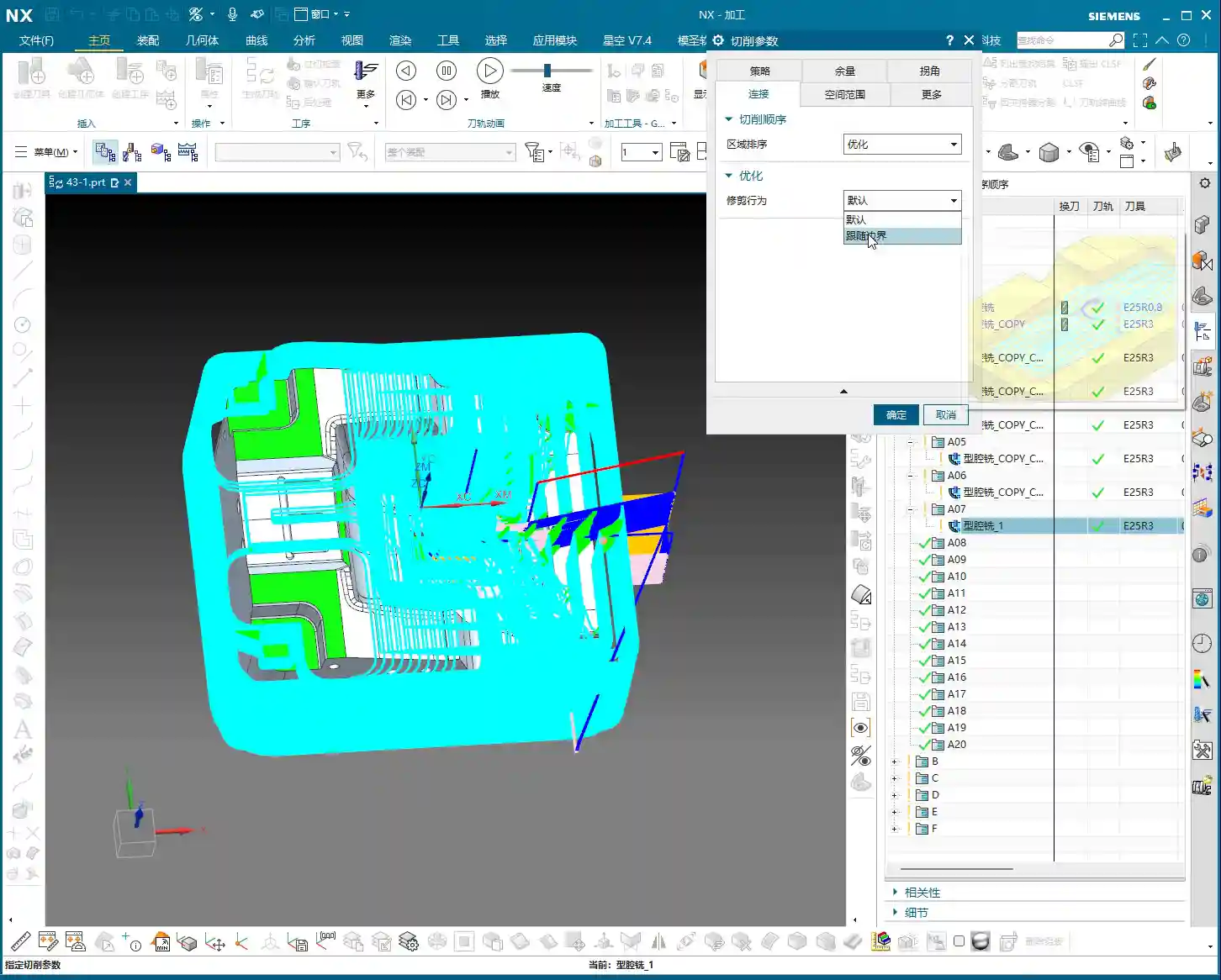
    • Connections: Change the connection type from default to “Move” to prevent unnecessary tool lifts and air cuts.
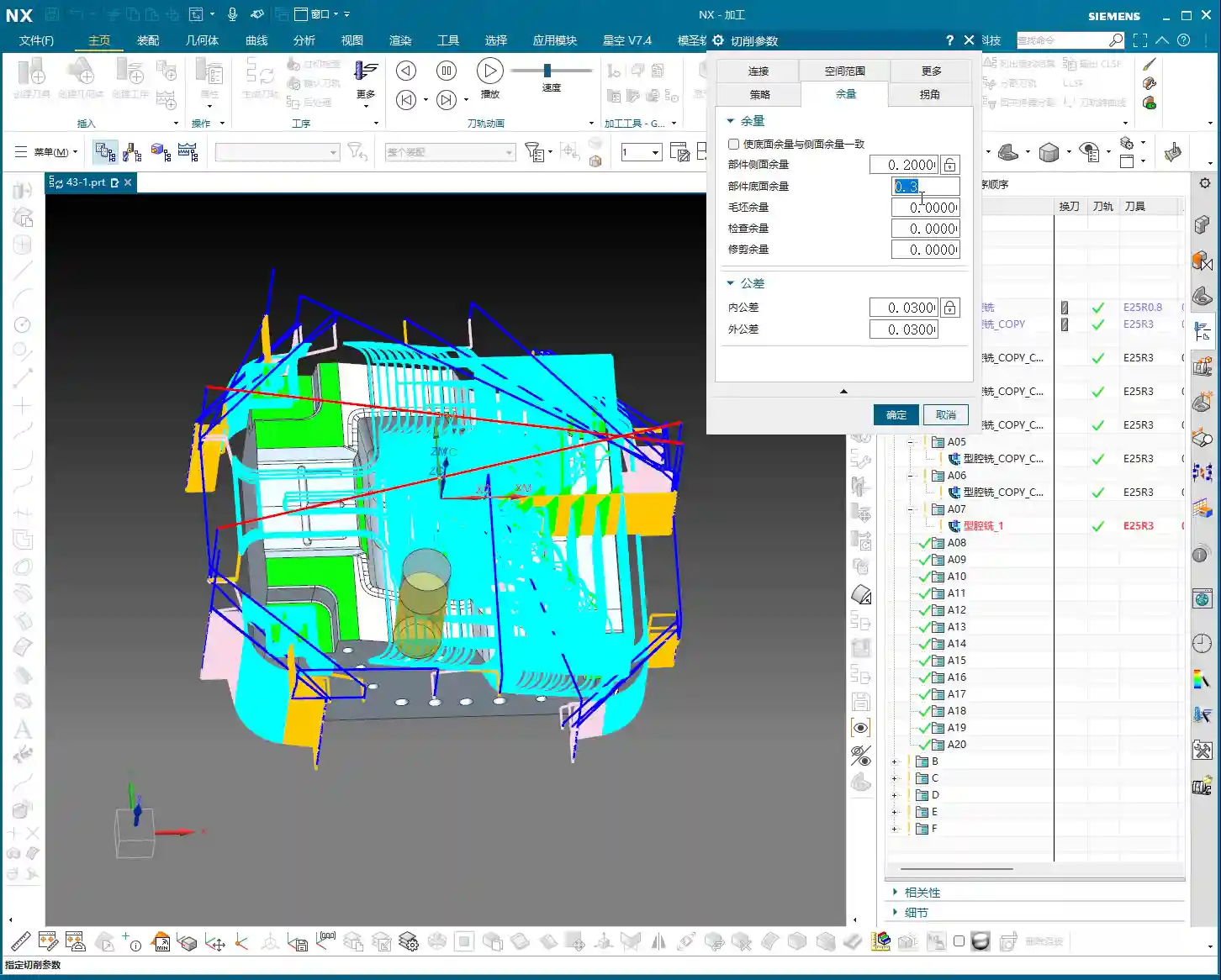
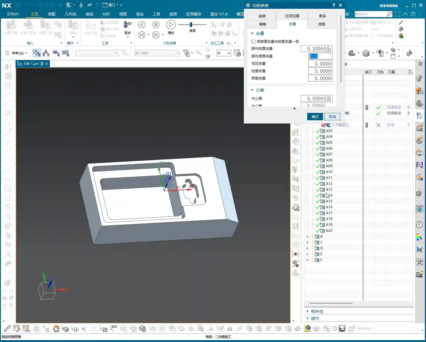
    • Stock: For a corner cleanup operation, set the stock directly to 0. Our goal is to remove all the excess material.

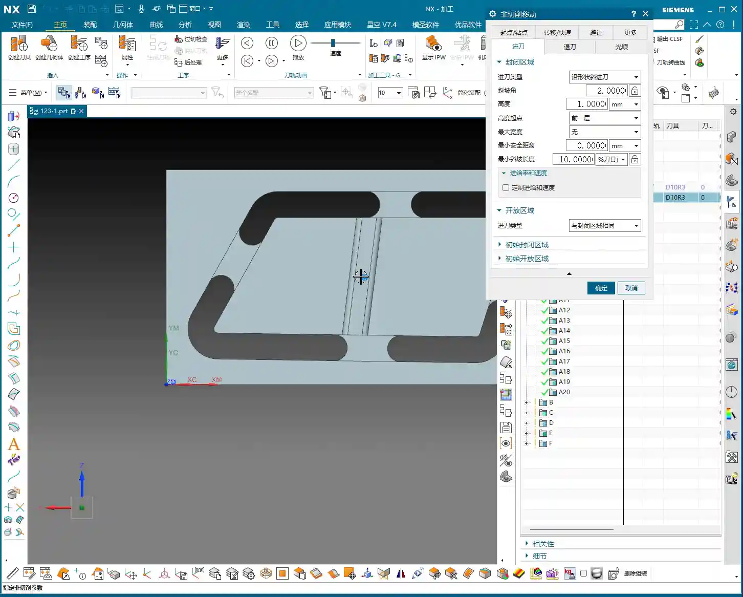
    Tool Entry/Exit Strategy: Avoiding Collision Risks

    As soon as the program ran, I immediately spotted an issue: the tool entry/exit was problematic, preventing the tool from safely entering and retracting. This is one of the most common mistakes made by beginner programmers!

    • Original Problem: The tool entry/exit path was unreasonable, prone to scratching the workpiece or making air cuts.
    • Solution:

      • Change the tool entry/exit method to “Same as Open Area”, allowing the tool to enter and retract in obstacle-free regions.
      • Select “Arc Engage” for the tool entry method, with a radius of 1 millimeter. Arc engagement effectively prevents the tool from plunging directly into the material, reduces impact, protects the tool, and results in a better surface finish.

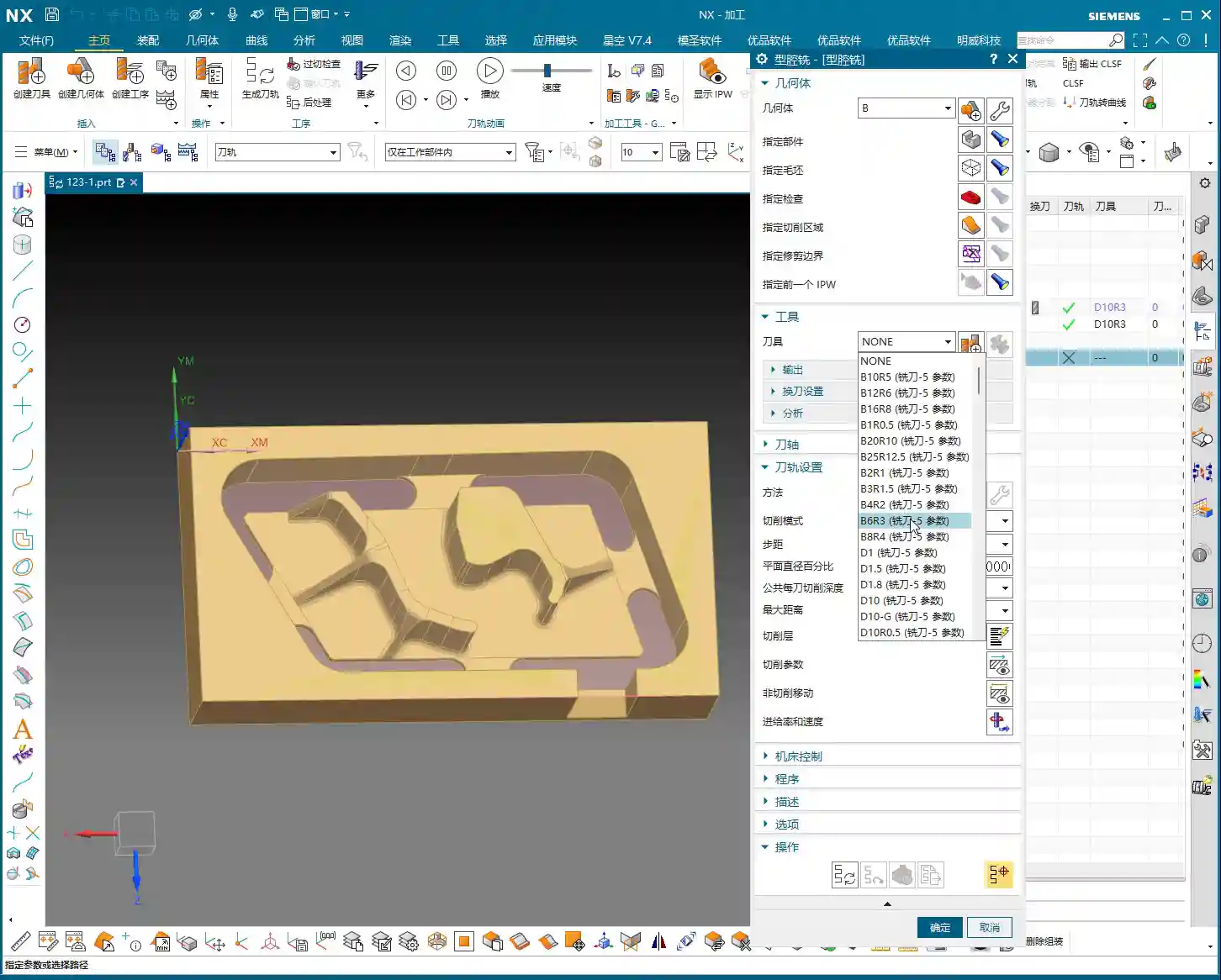
    Tool Selection and Boundary Handling

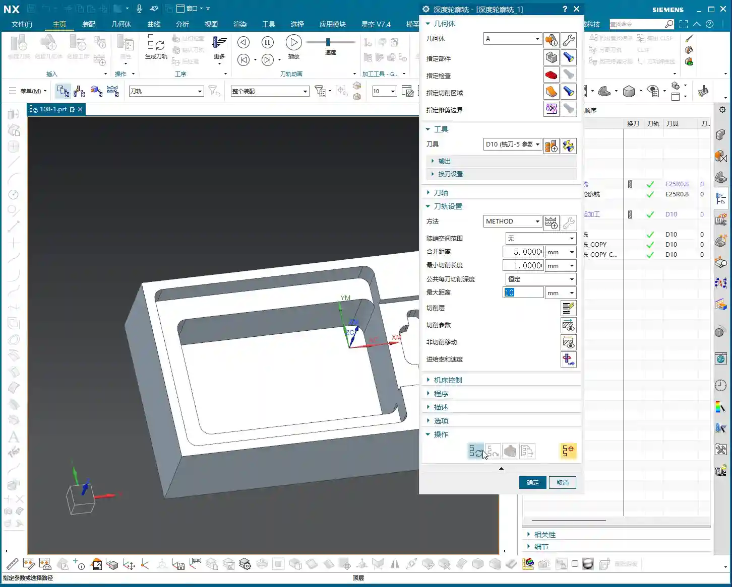
    For this corner cleanup, we’ll choose a 10mm flat end mill (Ø10mm). Its size is suitable, allowing it to reach into narrower areas while maintaining sufficient rigidity. A Ø6mm tool might be too weak.

    Next, I noticed that a certain spot might not have been thoroughly cleaned due to the toolpath, which is “not ideal.” However, it’s not a major issue. For the roughing stage, as long as it doesn’t affect subsequent finishing, occasional minor imperfections can be temporarily “overlooked.” We need to learn to prioritize and not get bogged down over-focusing on minute details during roughing; that’s not a good practice.

    Second Side Machining: Efficiency and Strategy

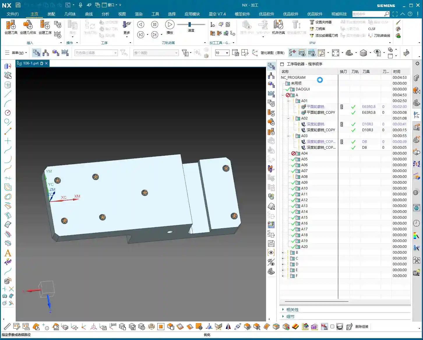
    With the first side done, we need to quickly flip the part and machine the other side. Remember, in the workshop, flipping the part and fixturing are among the biggest time costs, so programs must be correct the first time, minimizing rework.

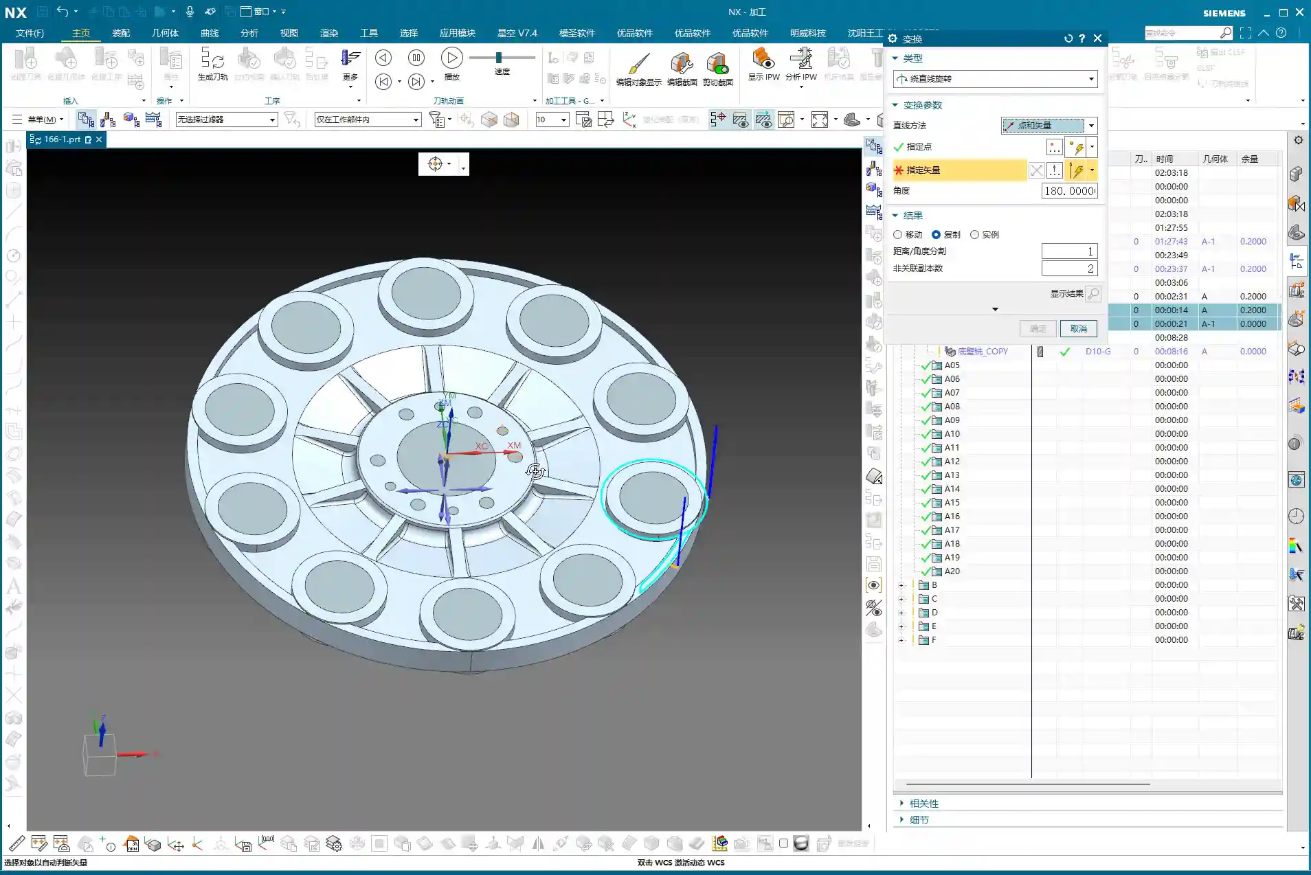
    Coordinate System Transformation and Program Reuse

    The quickest method is to transform the coordinate system, then copy the existing program and make minor modifications. Most parameters are universal.

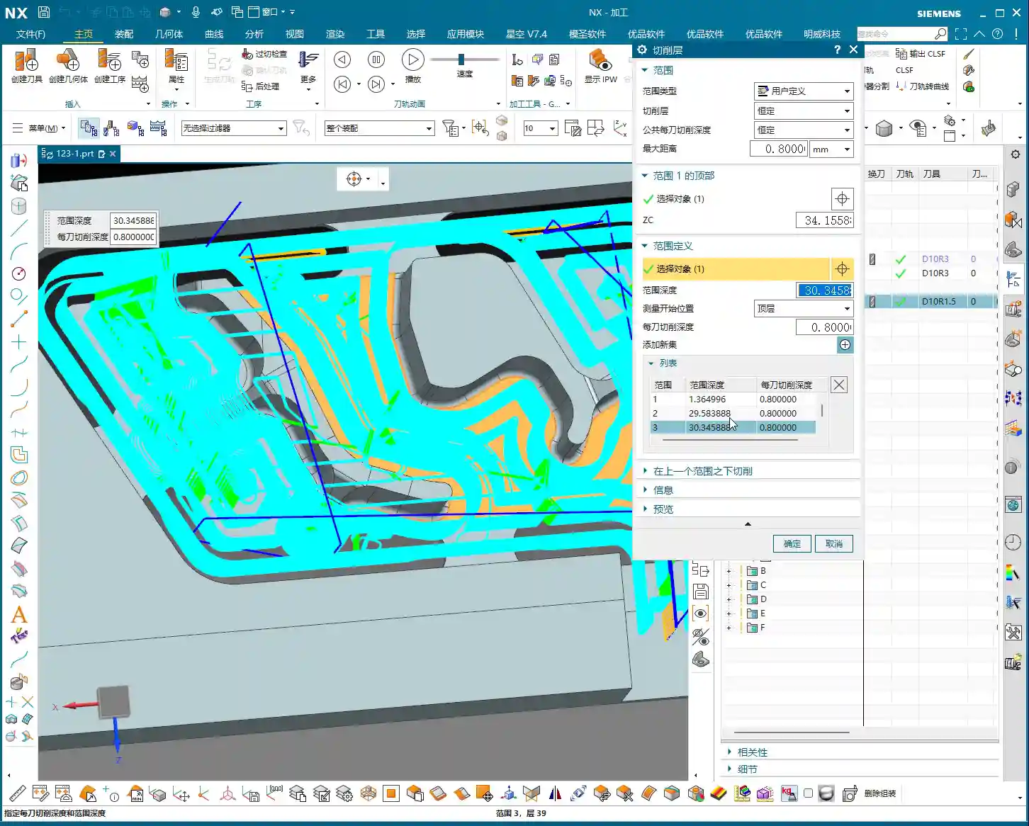
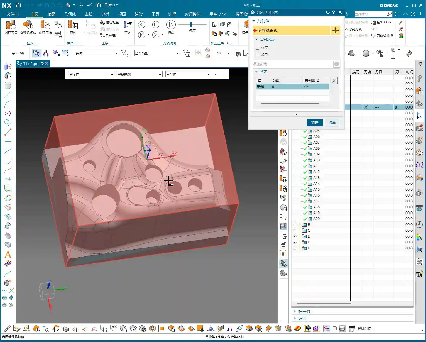
    • Blank Geometry Selection: The key is to select the blank geometry as this “B-side” after flipping. We previously machined the A-side; now we’re machining the B-side, and this absolutely cannot be mistaken.
    • Cutting Layers: For roughing, let the software automatically identify the cutting layers; it will find the last layer to mill.
    • Stock Setting: To be safe, we can leave a small amount of stock after corner cleanup, for example, 0.05 millimeters. This provides a margin for error in case of deformation or undetectable residual material during finishing. Never aim to machine to zero stock in one go; that risk is too high.

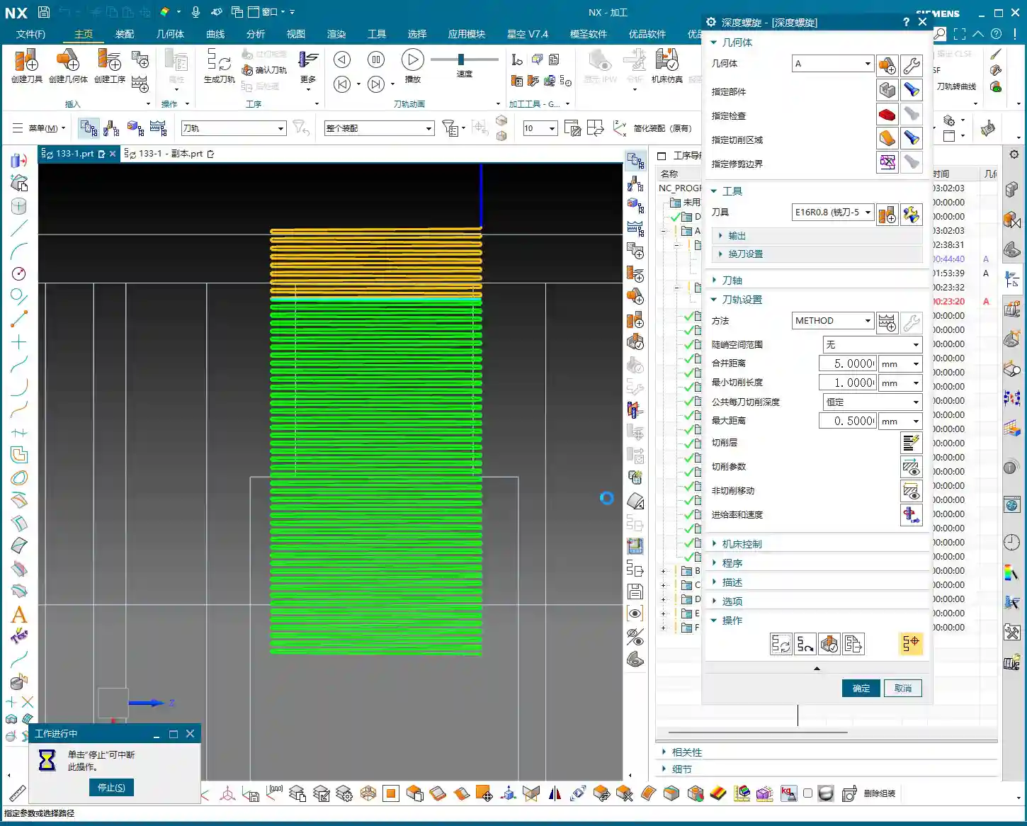
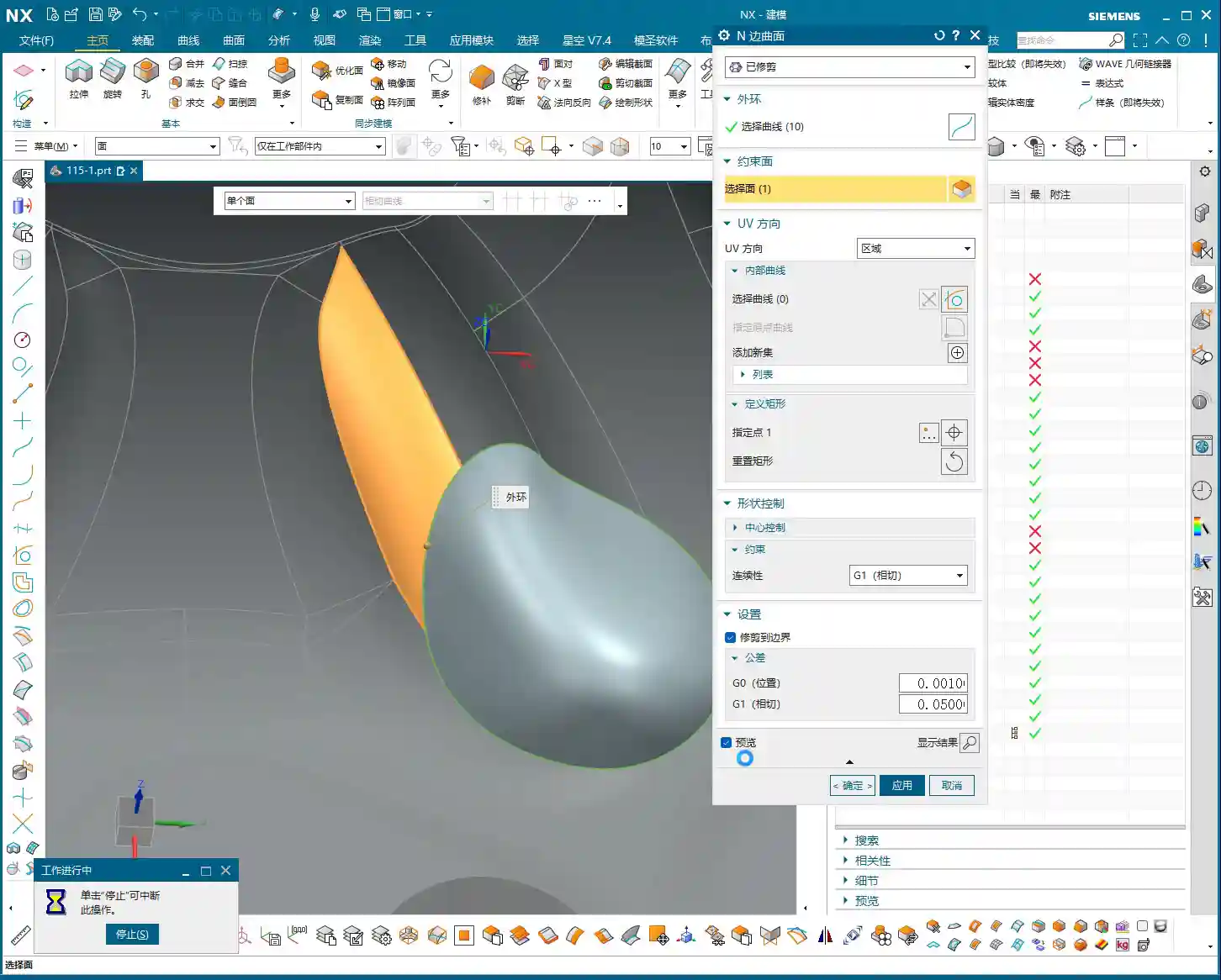
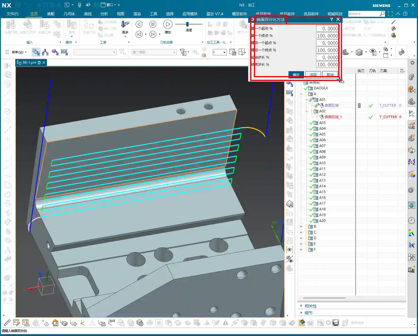
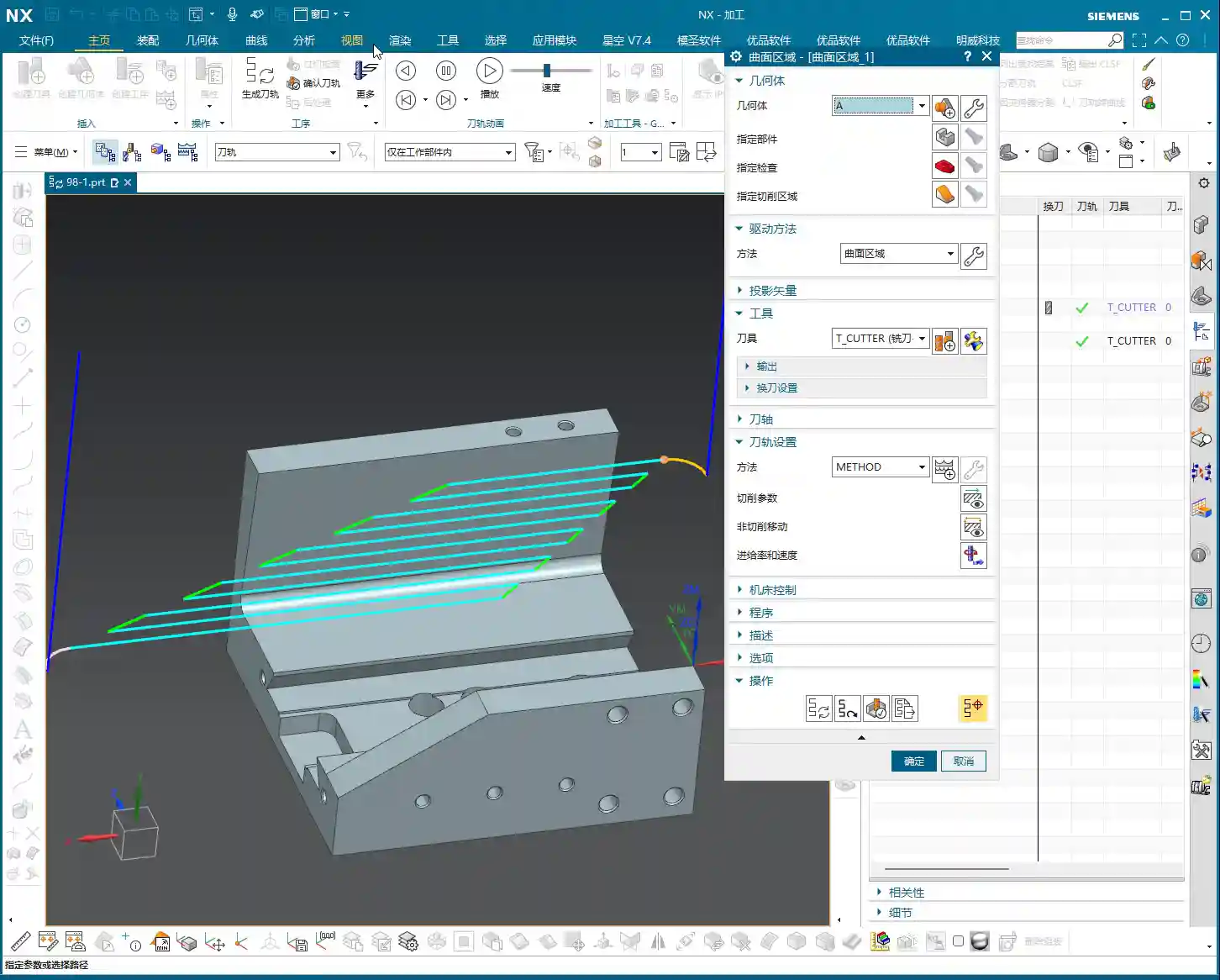
    “Surface Blocking” Technique: Handling Complex Regions

    While observing the machining of the second side, I found that some internal regions might experience redundant machining or be difficult to clean effectively. In such cases, we need to employ the “surface blocking” technique.

    • Purpose: To prevent the tool from entering areas that should not be machined, or to simplify toolpaths in complex regions.
    • Operation:

      • Select an “Offset Plane” to isolate the areas that need to be “blocked.”
      • Use the “Trim” function to cut away excess geometry, essentially defining a clear machining boundary for the tool.

    • Master Wang’s Tip: This trick is particularly useful when dealing with castings, forgings, or parts with complex internal structures. It effectively prevents “air cuts” and “heavy cuts.”

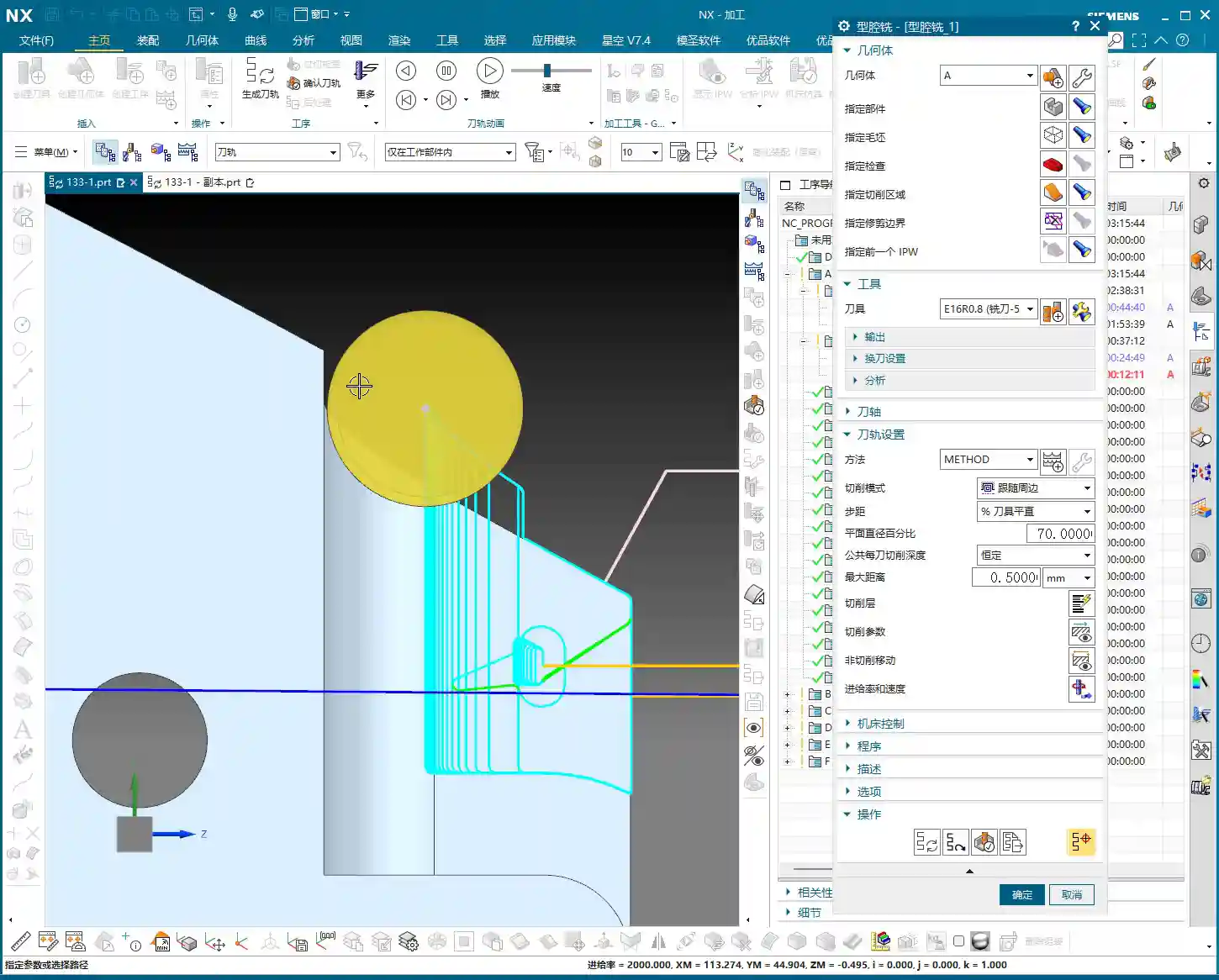
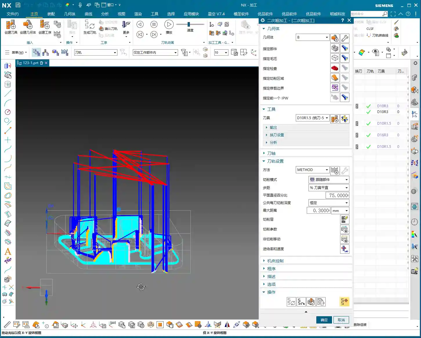
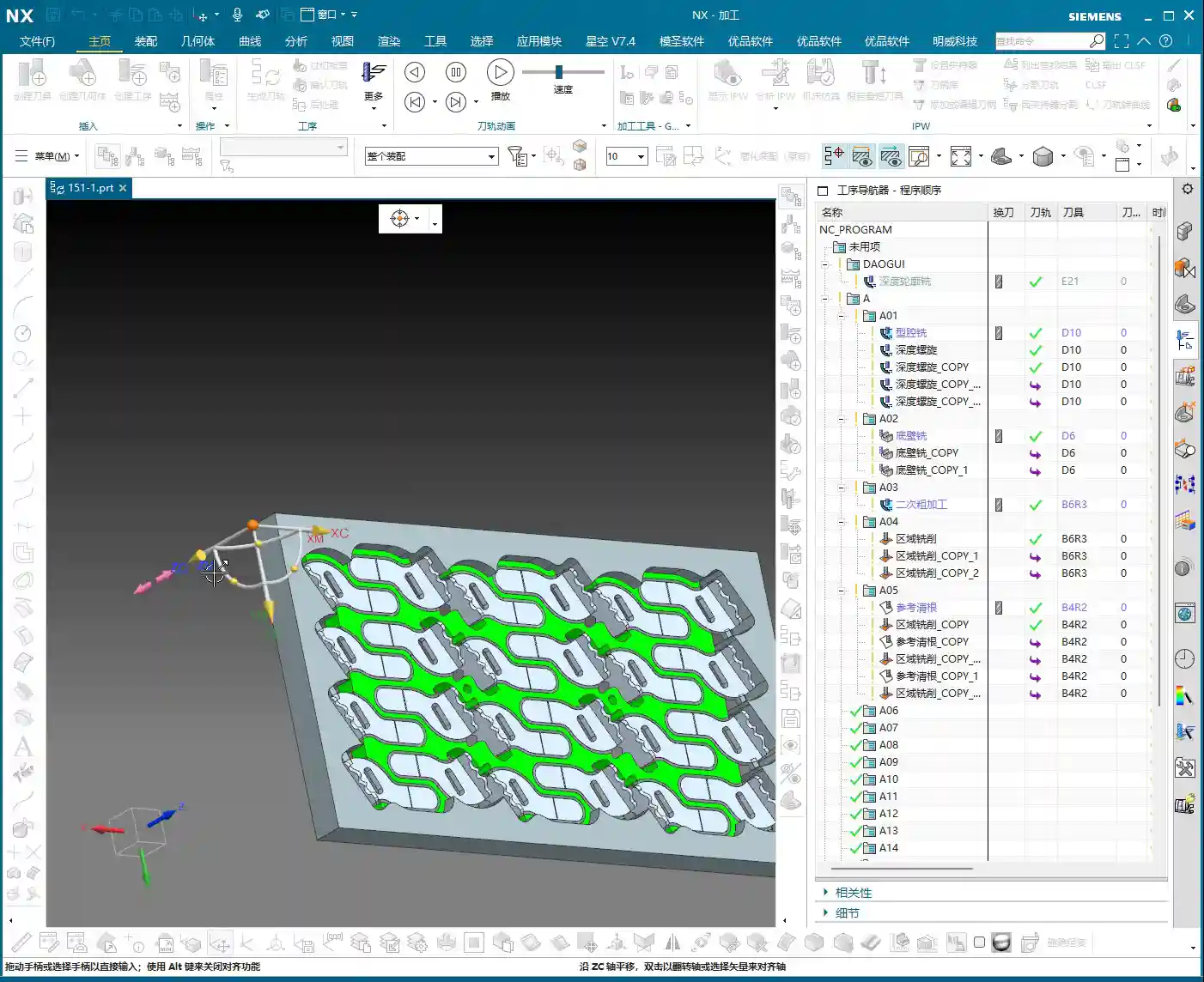
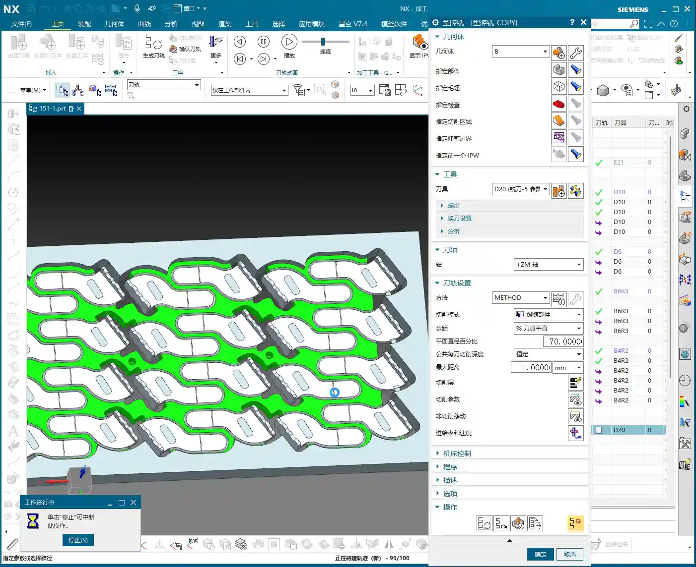
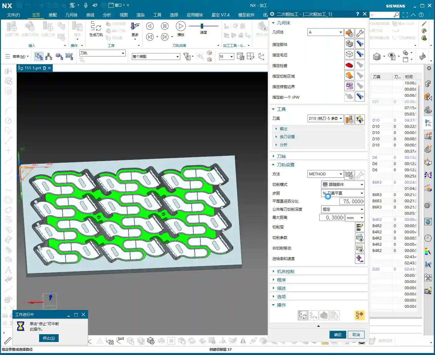
    Secondary Roughing: Larger Tools for Enhanced Efficiency

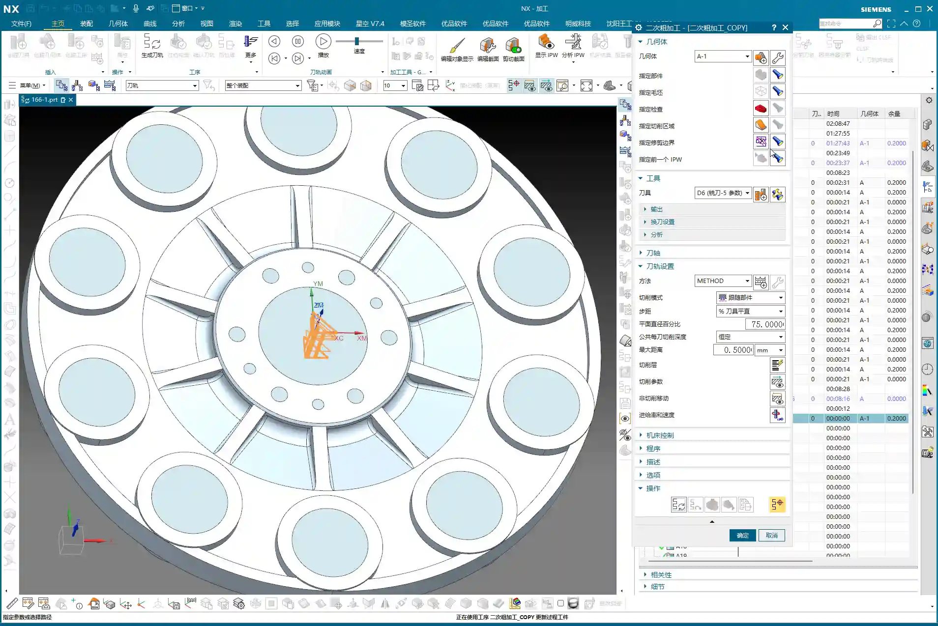
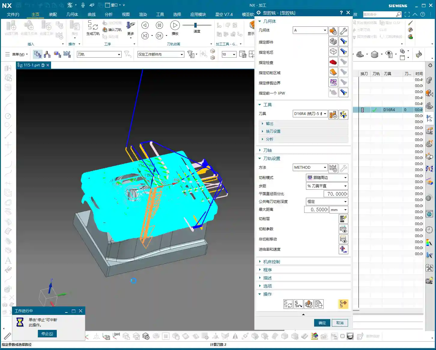
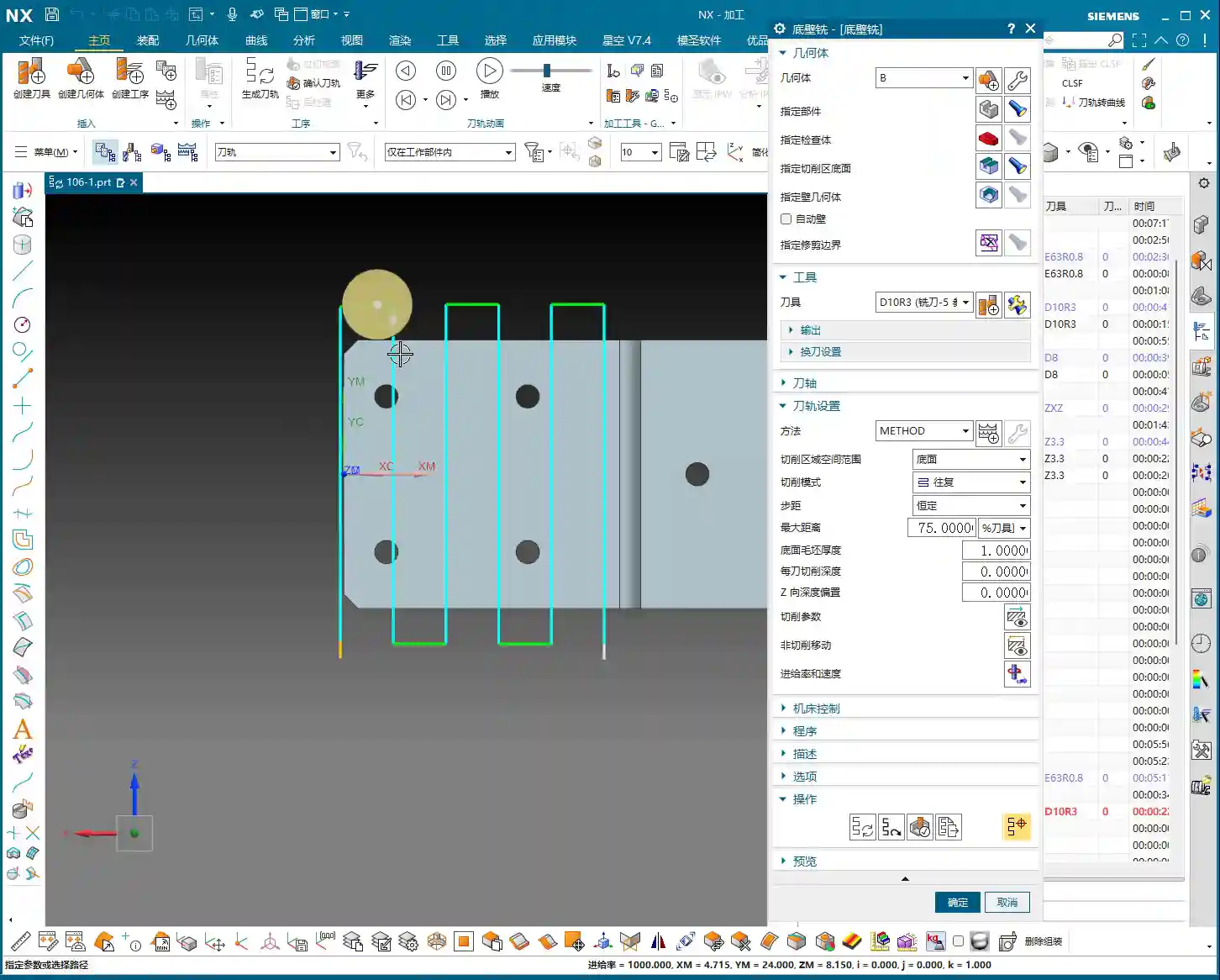
    With the initial roughing and corner cleanup complete, we now move to true “secondary roughing.” The strategy here is to use larger tools to quickly remove the bulk of the remaining stock.

    Tool Selection and Cutting Parameters

    Since this is secondary roughing, we need to “upsize” the tool to boost cutting efficiency.

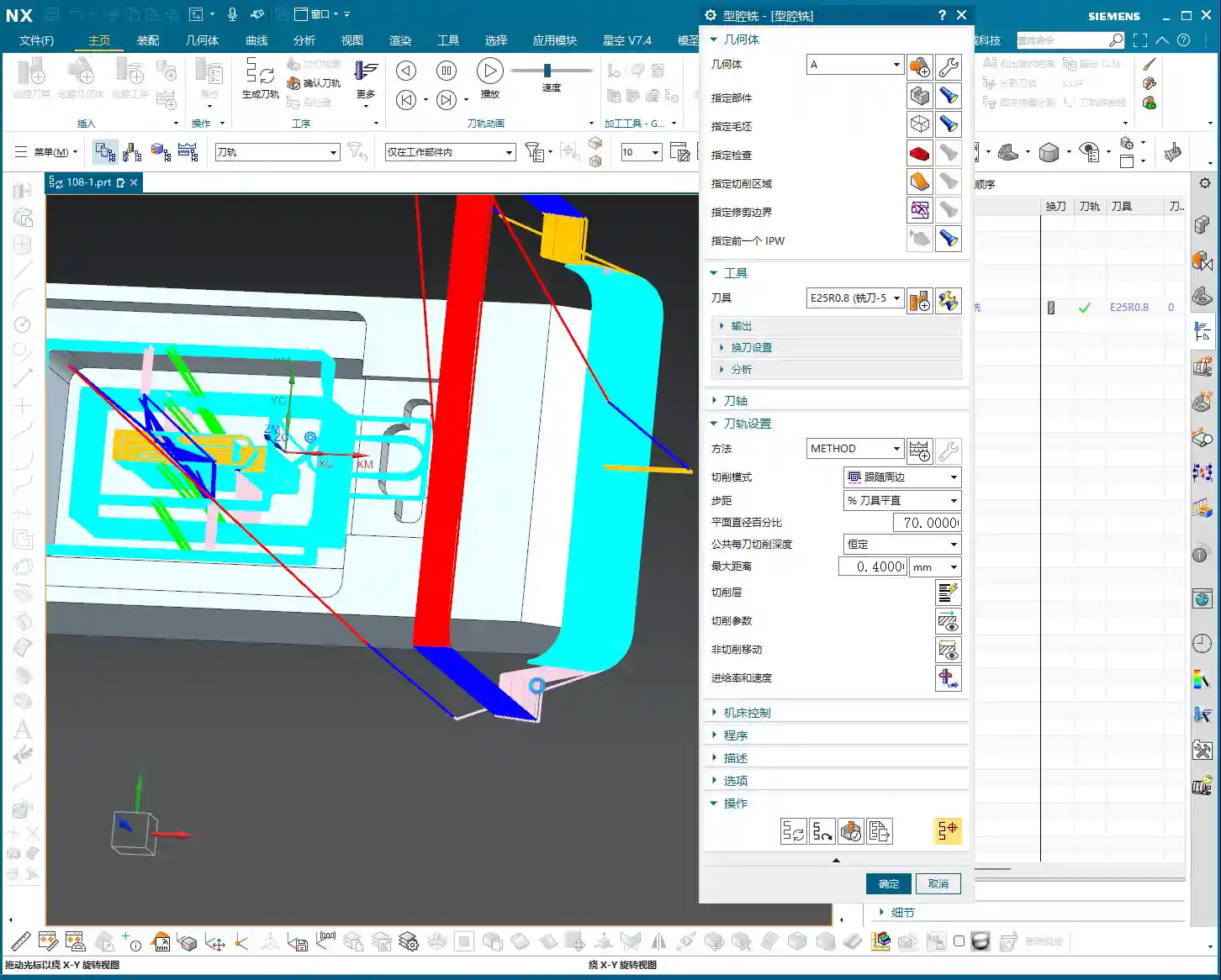
    • Tool: Go straight for a 20mm flat end mill (Ø20mm), or choose a 16mm or 18mm one depending on the specific situation. A larger tool allows for a greater volume of material removal per pass and fewer toolpaths.
    • Cutting Layers: With a larger tool, the previous fine “cutting layers” are no longer relevant; the software will determine them automatically.
    • Stock: For secondary roughing, leaving 0.3 to 0.5 millimeters of stock is appropriate, providing ample allowance for finishing passes.
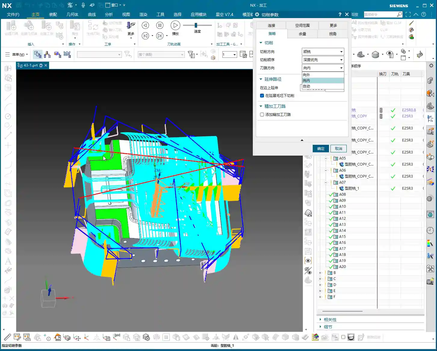
    • Stepover: Based on the tool diameter and material, we’ll set it to 0.35 millimeters here. This needs to be adjusted according to actual conditions and machine rigidity.
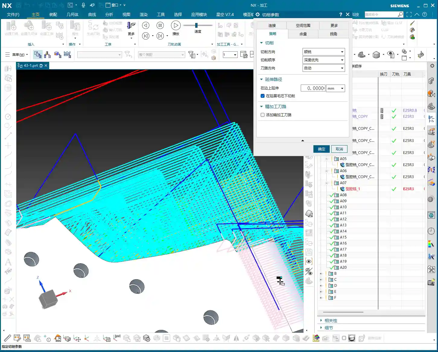
    • Tool Entry/Exit Distance: Set this to 1 millimeter to ensure safe tool entry and retraction.

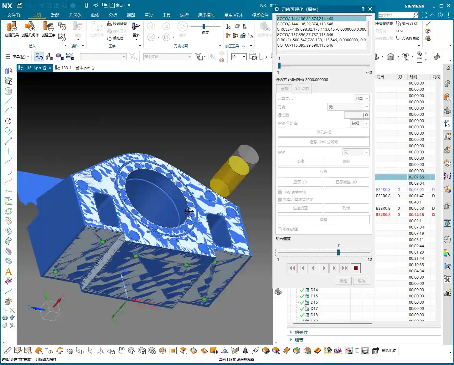
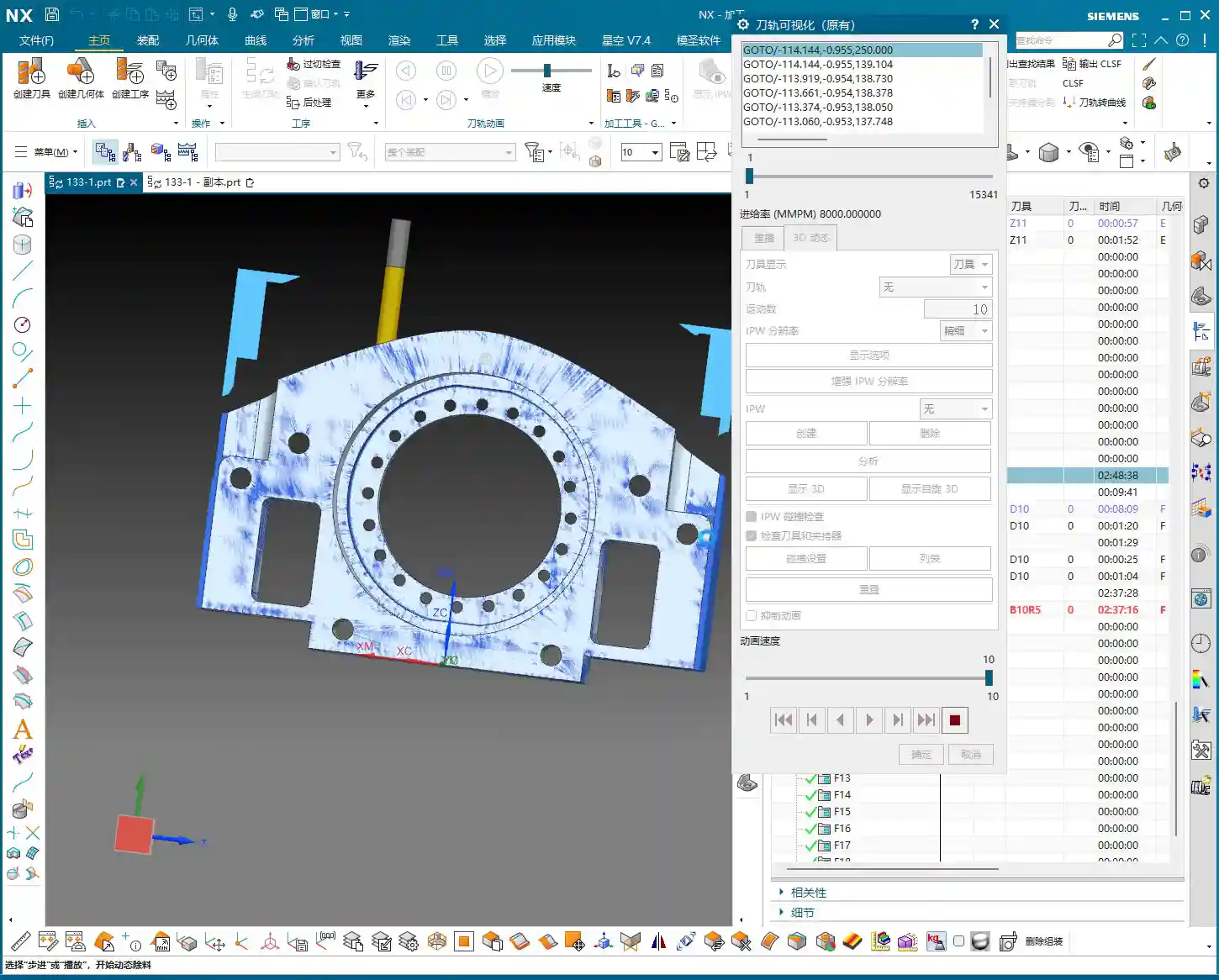
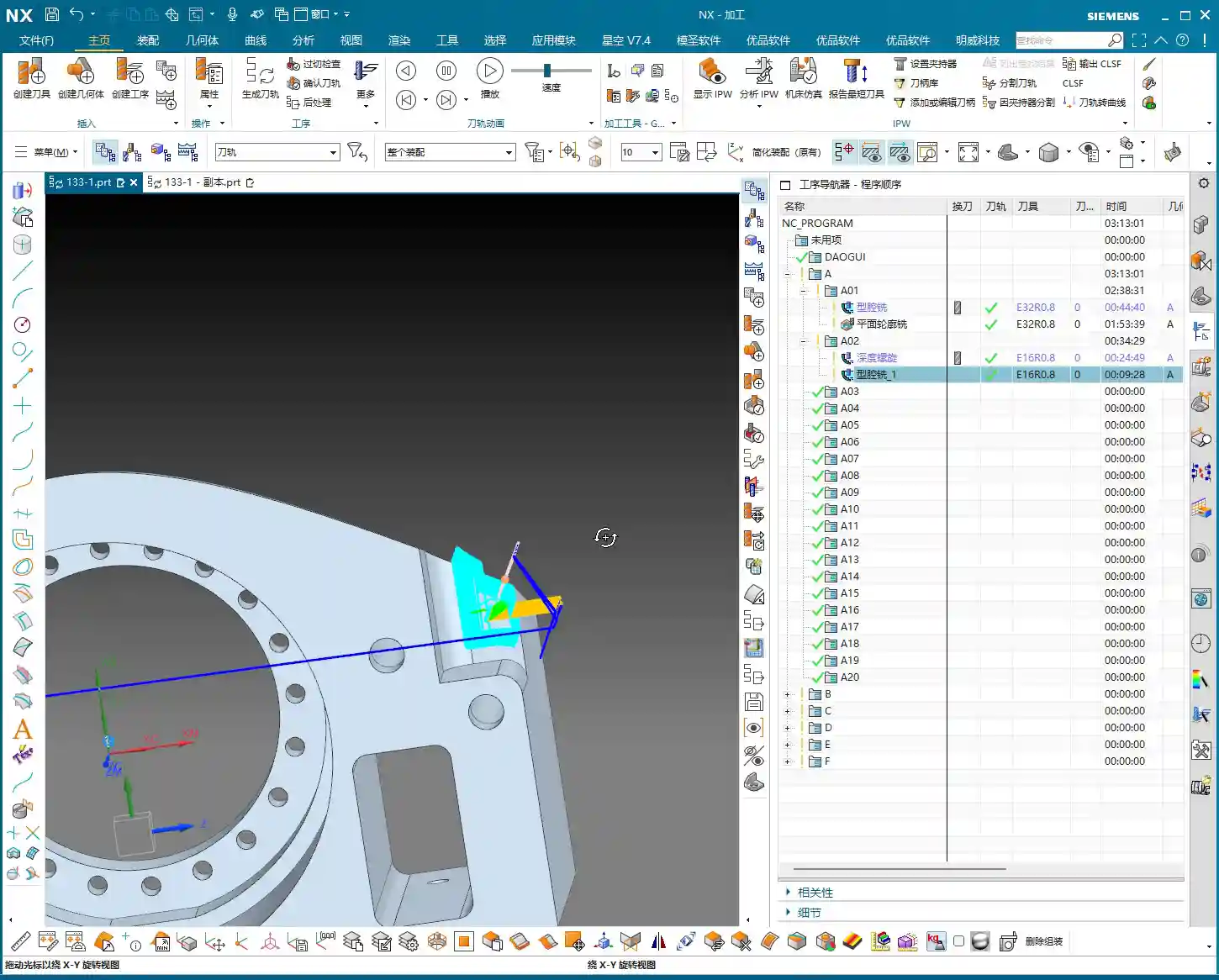
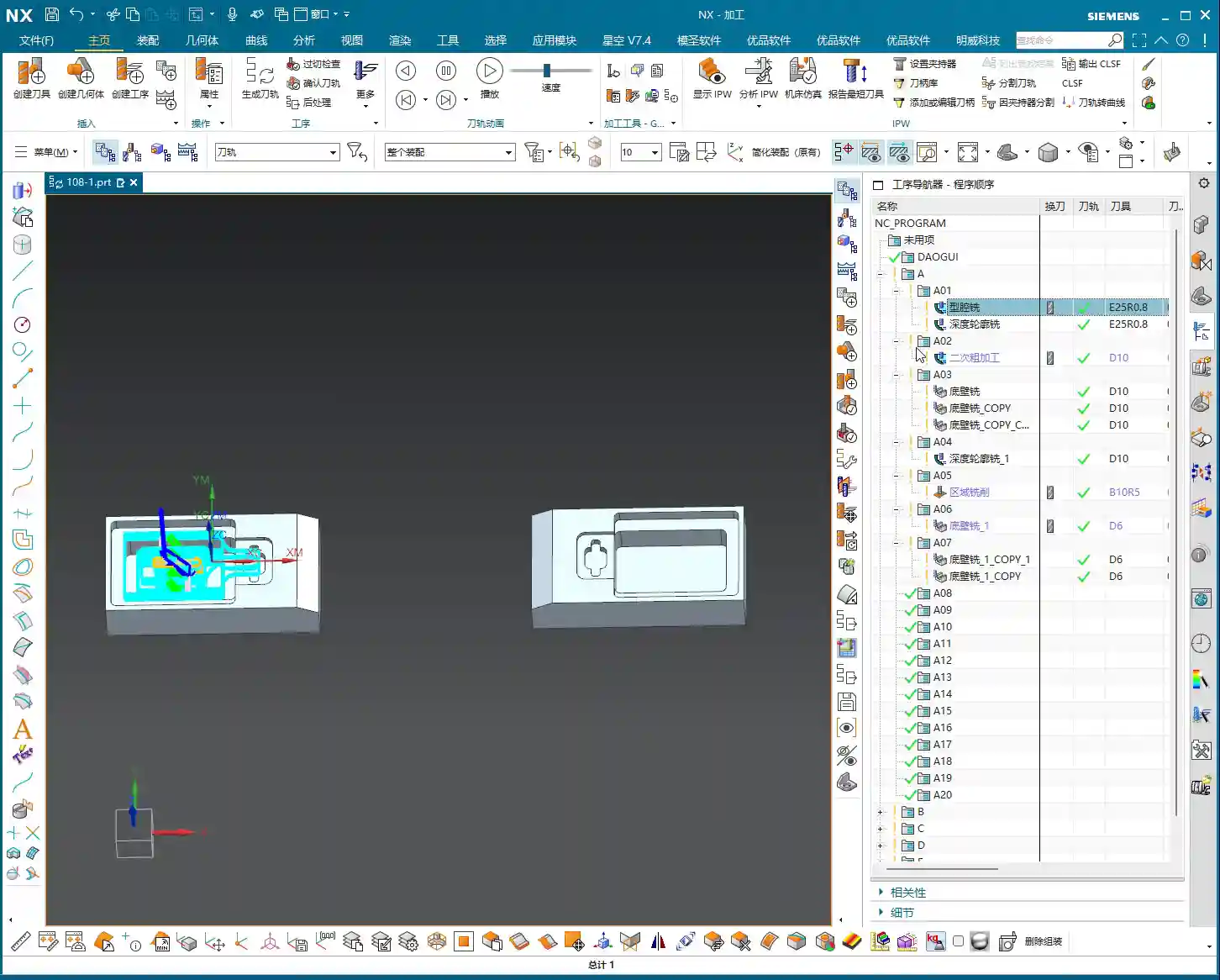
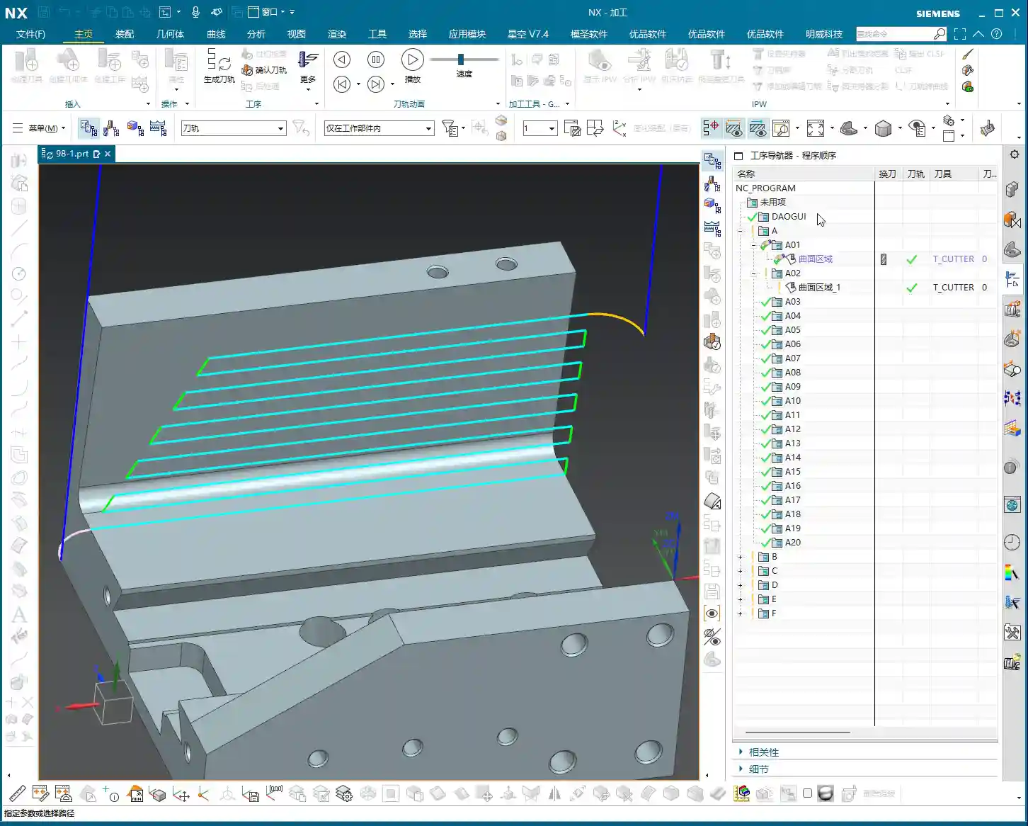
    Machining Simulation and Performance Evaluation

    After generating the program, you must carefully review the machining simulation. No matter how perfect the simulation, it’s never as real as watching the cutting sparks at the machine! But simulation can help us identify most problems beforehand.

    • Expected Outcome: Most areas should be cleaned up effectively by the Ø20mm tool.
    • Limitations: However, a Ø20mm tool certainly cannot reach all small corners and deep cavities. These areas must be left for subsequent finishing passes or smaller tools. During the roughing stage, don’t expect perfection everywhere; that’s unrealistic and uneconomical.

    Summary: Pitfall Avoidance Guide

    Alright, that concludes today’s lesson on secondary roughing programming. Master Wang has compiled a few practical tips to avoid common pitfalls—these aren’t things you’ll learn from textbooks:

    1. Computer Performance is a Bottleneck for Efficiency: NX program calculation, especially for complex surfaces or multi-axis simultaneous machining, is very resource-intensive. If your computer lags, it’s better to pause, optimize settings, or upgrade hardware, rather than pushing through. That’s a waste of time.
    2. Roughing Prioritizes Efficiency, Finishing Prioritizes Precision: For roughing, be bold with large tools, fast feed rates, and aggressive material removal. Don’t chase 0.01mm precision during the roughing stage; that’s counterproductive. However, always leave sufficient stock to provide adequate allowance for finishing passes.
    3. Tool Entry/Exit is the First Line of Safety: Improperly set tool entry and exit methods can, at best, affect surface quality, and at worst, lead to tool breakage or machine collisions. Always select appropriate arc or open-area entry/retraction based on workpiece geometry and tool characteristics.
    4. Pitfalls After Program Duplication: Copying programs saves time and effort, but the most common mistake is forgetting to modify critical parameters like geometry, blank, stock, and machining direction. Always double-check these after every copy. Just like today, I almost copied the geometry from the A-side to the B-side and forgot to change the machining face—that would have been a “wasted effort.”
    5. “Surface Blocking” is a Lifesaver for Complex Parts: For parts with deep cavities, complex internal structures, or regions that shouldn’t be machined, effectively utilize “surface blocking” or “area restriction” functions. This significantly optimizes toolpaths, preventing air cuts or damage to the workpiece.
    6. Multi-axis Programming is a Challenge: In the future, we’ll cover 4-axis and 5-axis simultaneous machining. These involve even greater computation and are more prone to programming errors, requiring more patience and experience. Be prepared, so you don’t get “stuck” when NX calculates the program.

    Alright, that’s it for today. Go practice more, commit these tips to memory, and we’ll pick up next time!

    [/CONTENT]

    👤 About the Author:
    The author is a veteran CNC machining professional with 15 years of industry experience, specializing in UG NX programming. This article is an original work representing personal practical insights.

    ⚠️ Copyright Notice: Unauthorized reproduction or distribution without prior communication is strictly prohibited.

  • Siemens NX Programming for Backside Finish Milling: Master Wang’s Hands-on Guide to Overcoming Uncle

    📝 Key Takeaways:

    Backside Finish Milling Programming: Practical Tips and Pitfall Avoidance Guide

    Step One: Analyze the Problem, Pinpoint the Root Cause

    Listen up, lads! Today we’re talking about programming for finishing the backside of a component. Don’t be fooled, it might seem like a simple finishing pass, but the higher the demands for flatness and surface finish, the more pitfalls you’ll encounter. Textbooks teach you a bunch of theory, but once you run it on the machine, you might just stare blankly. Today, Master Wang will show you how to get this job done, not just cleanly, but efficiently!

    Initial Attempts and Challenges with Bottom Face Finishing

    Let’s start with a standard operation: select the bottom surface to be machined, pick a suitable tool (for example, a D10 flat end mill), set the cutting parameters, and initially leave a small amount of stock. Then generate the toolpath and check the result. And just like that, problems arise!

    Master Wang’s Insight:

    “Look at this toolpath—it doesn’t go all the way to the edge; it turns inward or even breaks off entirely! Isn’t this a classic case of ‘not cutting to the edge’? If that little bit of material on the edge isn’t cleared, how can you expect a good finish? It’s a waste of time!”

    This situation often occurs because Siemens NX, when calculating the toolpath, defaults to not allowing the tool’s center point to exceed your selected machining boundary. This is especially true when your machining boundary is a right angle, and the tool diameter perfectly matches the boundary dimension (for example, a D10 tool hitting a 10mm boundary); it just absolutely refuses to extend even a hair further.

    Step Two: Master Wang’s Secret — Auxiliary Body Construction, Expanding the Toolpath Boundary

    When you encounter this, don’t panic! I’ve been dealing with machines for 15 years, and I’ve seen these little tricks countless times. Textbooks might tell you to switch to a smaller tool or set a negative stock allowance, but those are just temporary fixes. The most reliable, flexible, and efficient method is to add an auxiliary sheet body!

    Precise Measurement and Auxiliary Sheet Body Creation

    1. Measure the Boundary: First, we need to measure the outer dimensions of this bottom surface. For instance, on our part, the radius from the center point to the bottom surface boundary is 145mm. Once we have that number, we can get to work.

    2. Draw Auxiliary Circle: Using the part’s rotational center as the origin, draw a circle with a radius of 145mm.

    3. Extrude to Sheet Body: Extrude this circle into a sheet body. The extrusion height can be arbitrary, as long as it covers your machining area; it’s just a temporary “dummy” body after all.

    4. Set Machining Area: Here’s the key! When programming, the selected machining area is no longer just the original bottom surface. Instead, you include the auxiliary sheet body we just created. This way, when Siemens NX calculates the toolpath, it will assume your boundary has expanded outwards, allowing the tool’s center point to travel further out and completely clear the stock at the corners.

    Master Wang’s Reminder:

    “This auxiliary sheet body must extend slightly beyond your actual machining boundary. How much? The radius of your tool, plus an additional 0.1~0.2mm stock allowance, is plenty. Don’t add too much, or you might hit something you shouldn’t, and that would be trouble!”

    Tool Diameter Micro-Adjustment – Backup Plan

    If you really don’t want the hassle of drawing an auxiliary sheet body, or if the part geometry is too complex and a sheet body is difficult to create, Master Wang has an emergency workaround. But remember, this method is a temporary fix, not a complete solution, and it’s less effective than using an auxiliary body.

    You can slightly reduce the diameter of the tool being used. For example, if you’re using a D10 flat end mill that theoretically should reach the edge but isn’t, you can change its diameter to D9.99. This allows the tool’s geometric center point to move slightly further out, connecting to that edge. However, use this micro-adjustment cautiously for parts requiring high precision, and it demands a good understanding of your machine’s accuracy.

    Master Wang’s Experience:

    “I typically use this small diameter adjustment when the finishing pass has zero stock allowance but still ‘can’t reach the corner’. While it’s not the ideal method, it can save you in certain emergency situations. But the core principle is still to control the toolpath boundary precisely!”

    Step Three: Sidewall Finishing and Toolpath Optimization

    Now that the bottom surface is taken care of, let’s look at the sidewalls. For the same part, the machining requirements for the bottom and sidewalls might differ. Let’s proceed with the sidewalls.

    Sidewall Toolpath Selection and Optimization

    Copy the bottom surface finishing program, then modify the parameters for machining the sidewalls. Choose an appropriate machining method, such as Planar Mill or Contour Profile; either can work.

    For sidewall finishing, a D10 flat end mill is commonly used, making a single pass from top to bottom with a stock allowance of 0. However, at this point, you might find that the toolpath travels too far, with excessive air cuts, leading to inefficient operation.

    Master Wang’s Secret Tip:

    “Look at this toolpath—it looks like it’s trying to finish the entire workbench! This wastes time, wastes tool life, and most importantly, wastes money! In this situation, we need to limit its Space Percentage or Cutting Range. For example, adjust it to 30%, making the toolpath more compact, only traveling back and forth in the truly necessary cutting areas, reducing air cuts, and boosting efficiency. Don’t just look at software simulations; observe the cutting sparks and actual results!

    If the sidewalls have small radii or more complex surfaces, a D10 flat end mill might not be sufficient. In that case, we can copy the program again and switch to a D6 ball end mill specifically for Corner Cleanup of those small radii or surface areas. The machining boundary must also be set correctly to ensure the tool only works within the target area.

    Step Four: Rapid Programming for Symmetrical Parts – Transform and Copy

    Many parts are symmetrical, such as features distributed in a circular array. If you program each one individually, you’ll be doing it until the cows come home! Siemens NX’s Transform function is designed precisely for this—it’s a massive time-saver!

    Rotational Copy of Toolpath Programs

    1. Select Programs: First, select the already programmed bottom surface finishing program and sidewall finishing program (or any other programs you need to copy).

    2. Select Transform Type: Go to the “Edit” menu for the program in the “Operation Navigator,” find “Transform,” and select “Rotate.”

    3. Set Rotation Parameters:

      • Rotation Point: Select the part’s geometric center as the rotation center point.
      • Rotation Vector: Select the vector that coincides with the rotation axis, typically the Z-axis.
      • Rotation Angle: If the part has 10 equal divisions, the total angle is 360 degrees, so each division is 360 / 10 = 36 degrees.
      • Number of Copies: This is crucial! Since you already have one original program, you only need to copy 9 additional instances (for a total of 10, subtracting the original). Don’t foolishly copy 10, or you’ll end up with an extra one.

    4. Generate: After confirming the parameters are correct, click OK. Siemens NX will automatically generate the toolpath programs for the other symmetrical areas, saving you a huge amount of repetitive work.

    Master Wang’s Takeaway:

    “This transform function is a powerful tool for boosting efficiency in real-world scenarios! In the same amount of time, others are still programming one by one, while you’ve already generated several sets. This is the true skill of a seasoned veteran, something you won’t learn just by clicking a mouse.”

    Step Five: Program Management and Important Notes

    Once programming is done, it’s not over. Proper program management and attention to small details can save you from many unnecessary headaches.

    Separate Storage for Different Tool Programs

    This is a very important habit! Programs for different tool diameters must never be placed in the same operation group!

    Master Wang’s Emphasis:

    “Listen closely! If you mix D10 toolpaths with D6 toolpaths, Siemens NX will give you an alarm! It assumes that since the tool has changed, the entire program needs to be recalculated. Then you’ll have to separate them one by one—what a hassle, right? So, diligently keep them separate. For example, put D10 programs in A03, D6 programs in A04—clear and concise. This not only facilitates management but also prevents software errors.”

    Always save your work after programming! Develop the habit of saving frequently to avoid losing work due to unexpected situations.

    Summary: Pitfall Avoidance Guide

    What Master Wang has taught you today is practical experience accumulated over 15 years of hard work in the shop. Remember these points, and you’ll avoid detours and achieve excellent results when programming finish milling of bottom surfaces in Siemens NX:

    1. Learn to use Auxiliary Sheet Bodies: When toolpaths fail to cut to the edge, don’t just think about changing tool diameters or negative stock allowances. Constructing an auxiliary sheet body to expand the boundary is the most flexible and thorough solution.

    2. Optimize Sidewall Toolpaths: Reduce unnecessary air cuts by adjusting the Space Percentage or cutting range to make toolpaths more concentrated and efficient. Improving machining efficiency directly reduces cost!

    3. Master Toolpath Transformation: For symmetrical parts, skillfully use rotate, mirror, and other transform functions to significantly boost programming efficiency and achieve more with less effort.

    4. Independent Program Management: Programs for different tools must be stored separately to avoid confusion and software errors, making subsequent management and retrieval easier.

    5. Combine Practice with Theory: Don’t just rely on software simulations. Think critically, observe carefully, and integrate actual machine operation, cutting sparks, and part finish. That’s the real skill!

    👤 About the Author:
    The author is a veteran CNC machining professional with 15 years of industry experience, specializing in UG NX programming. This article is an original work representing personal practical insights.

    ⚠️ Copyright Notice: Unauthorized reproduction or distribution without prior communication is strictly prohibited.

  • Siemens NX CNC Machining Practice: Complete Part Simulation, Integrated Roughing and Finishing Pass

    📝 Key Takeaways:

    NX CNC Machining Practice: Complete Part Simulation

    Hello everyone, I’m Engineer Wang. Today, let’s discuss how to streamline the entire…

    [VIDEO_HERE]

    Hello everyone, I’m Engineer Wang. Today, let’s discuss how to streamline the entire Siemens NX (UG) CNC machining process for a part, from roughing to finishing, and all the way through final simulation and verification. This session marks the final stage of machining for this particular part, focusing on finishing all the top surfaces to complete the job. Listen up, this is all based on real-world experience.

    Coordinate System and Stock: Laying a Solid Foundation

    First, we need to establish the ground rules. The coordinate system and stock are the foundation of our machining. If the foundation isn’t solid, any structure built on top, no matter how elaborate, will be useless.

    Coordinate System Selection and Clamping Considerations

    For the final operations on this part, I’ve positioned the Work Coordinate System (WCS) at the front clamping location. Why there? Because this most accurately reflects the actual clamping setup and makes it easier to observe the toolpaths. X-axis centered, Y-axis to the front, Z-axis at the bottom face – this is the most reliable approach. Don’t just think about a pretty model; consider if the part can be securely clamped on the machine and if there will be any interference.

    Stock Size Setting is Critical

    When creating the program group, select a milling type, for instance, “Face Milling”. Initially, I tried a stock size of 200 mm. After some consideration, it felt a bit small, so to be safe, I directly set it to 250 mm. Better to be a bit larger than too small; leave sufficient material for flexibility. During the later finishing passes, if the stock size is set improperly, “undercutting” or “overcutting” issues can easily occur, which always leads to rework, wasting both time and effort.

    Roughing Strategy: Aggressive Cuts, Efficiency is King

    Roughing emphasizes “speed, precision, and aggressiveness” to remove most of the material, easing the burden for subsequent finishing passes. However, speed doesn’t equate to recklessness; you need to be precise with tool selection, parameters, and toolpaths.

    Tool Selection and Machining Area Division

    For the upper section of this part, we have two approaches. The first is to perform roughing with a D10 or D16 tool to remove bulk material, then switch to a D10 tool for a finishing pass. The second is to use a D12 tool directly to complete the job in a single pass. I generally prefer the second option, as it avoids tool changes and, provided the tool’s rigidity is sufficient, it’s more efficient to complete in one shot.

    Cavity Milling and Bottom Face Roughing Parameter Settings

    We’ll use Cavity Milling for side wall machining. Select a D12 tool, and set the single Depth of Cut (DOC) (step) to 0.2 mm. This parameter needs to be adjusted based on the material and machine rigidity; don’t just blindly chase speed. For the side walls, we’ll initially leave 2 mm of stock, and also leave 2 mm of stock on the bottom face. Why? Because the bottom face will be finished later with a smaller tool; leaving a larger allowance now prevents interference with the larger tool. Cutting layer settings are crucial; don’t let the tool plunge directly to the bottom; leave enough space for the subsequent finishing pass.

    For bottom face roughing, we’ll use a D10 tool. The single Depth of Cut (DOC) will still be 2 mm, and the bottom face stock allowance will be 0.15 mm. The purpose of roughing is to remove the bulk material, leaving just a small allowance for the finishing pass.

    Avoid Air Cuts and Optimize Toolpaths

    No matter how powerful NX’s simulation is, it cannot replace your judgment of actual cutting conditions. Air cuts not only waste time but can also lead to machine chatter, affecting machining quality. When programming, always consider how to make toolpaths more compact and reduce unproductive travel. For instance, the stock allowance set earlier for the bottom face is specifically to prevent the large tool from making ineffective cuts, or it’s a deliberate arrangement for the subsequent finishing pass.

    Finishing Passes: Details Determine Success

    Roughing removes the bulk material; finishing is about refining the contours. At this stage, toolpaths, stock control, and cutting parameters must be meticulous; there’s no room for error.

    Implementing Bottom Face and Side Wall Finishing Passes

    After completing bottom face roughing, simply copy that operation. Set the bottom face stock allowance to 0, and that becomes your finishing pass. The same applies to the side walls: copy the roughing operation and set the side wall stock allowance to 0. Remember to change the cutting layers to automatic, allowing the system to determine them. At this point, you’ll need to observe the cutting sparks and listen to the sound. If something sounds off, stop immediately and check.

    Flexible Use of Tool Extension

    When making a finishing pass, if you feel the tool isn’t cleanly cutting the edges, you can appropriately add a bit of tool extension, for example, 2 mm. This ensures the tool completely exits the workpiece, preventing residual material. But don’t extend blindly; excessive extension could lead to collision with the fixturing or moving to an unintended area, causing an accident.

    Complex Area Machining: Ball-End Mills to Tackle Tricky Corners

    For areas with curved surfaces or fillets, you must use Area Milling. We’ll select a ball-end mill, select the entire area directly, and perform a finishing pass. Since roughing has already been performed, there’s no need to leave any stock allowance here; go straight to the final depth. The advantage of a ball-end mill is its ability to handle various complex surfaces and transitions, resulting in a smoother part surface.

    Precise Control of Cutting Layers to Avoid Recutting

    When performing Area Milling, a common issue is frequent air cuts. NX allows you to solve this by controlling the cutting layers. For instance, you can specify the tool to start machining from the side wall of the part, rather than plunging from thin air. This not only reduces idle travel time but also prevents secondary cutting of already machined surfaces, ensuring surface quality.

    Simulation Verification: Seeing is Believing, Mitigating Risks

    Once programming is complete, the most important step is simulation. Don’t think NX simulation is just for show; it’s your “safety fuse” for discovering potential issues and preventing machine crashes!

    Critical Precaution Before Simulation

    Listen up, this is a hard-learned lesson from Engineer Wang: Before performing any simulation, always save your program! Although NX’s simulation is powerful, it can sometimes freeze or even crash when encountering complex toolpaths or model issues. If you haven’t saved at that point, all your previous effort will be wasted.

    Key Points to Observe During Simulation

    During simulation, don’t just watch how fast the tool moves; observe carefully:

    • Are there any overcuts or undercuts? Check if the machined model surface is smooth, if there’s any excess material (undercut), or if areas that shouldn’t be cut have been removed (overcut).
    • Is there any tool-fixturing interference? This is a critical mistake! The purpose of simulation is to detect interference points beforehand to prevent machine crashes.
    • Is the toolpath logical and efficient? Are there excessive air cuts? Are entry and exit moves smooth? These all relate to machining efficiency and surface quality.

    Although this part appears simple, we actually divide it into six operations: roughing, semi-finishing, followed by heat treatment, and then the final finishing passes. Don’t underestimate these steps; not one can be skipped, and each has its own rationale.

    “Complex” Operation Planning for Seemingly Simple Parts

    In the simulation, we will see:

    1. First, roughing down to the bottom face to remove the bulk of the material.
    2. Then, preparation for finishing (semi-finishing), at which point heat treatment may still be required, so some stock allowance is left.
    3. Next is drilling.
    4. Finally, the final finishing and finish cuts, machining all surfaces to the required dimensions.

    Although some minor display issues may occur during simulation, such as lag or incomplete graphic rendering, as long as the core toolpaths and cutting actions are correct, these are usually not major problems and can be ignored. What’s important is that through simulation, we can ensure all machining steps and toolpaths meet requirements and that no mishaps occur during actual machining.

    Summary: Pitfall Avoidance Guide

    • Secure Coordinate System Setup: Always prioritize actual clamping for stable and precise machining.
    • Sufficient Stock Size Allowance: Better to be slightly oversized than undersized, leaving room for subsequent operations and avoiding undercuts.
    • Roughing for Efficiency, Finishing for Detail: Proper tool and parameter selection, precise stock allowance control.
    • Eliminate Air Cuts: Optimize toolpaths and precisely control cutting layers to reduce unproductive travel and enhance efficiency.
    • Ball-End Mills are Key for Surface Machining: Utilize ball-end mills effectively for complex contours, but pay attention to cutting layer control.
    • Always Save Before Simulation: This is your last line of defense for protecting your work!
    • Simulation is Not Just for Show, but for Insight: Pay attention to overcuts, undercuts, interference, and toolpath rationality.
    • Multi-Operation Processes are Standard: Many seemingly simple parts inevitably require multiple operations to ensure quality, especially those involving heat treatment.

    That concludes this discussion. Remember, textbook theory is foundational, but real-world experience on the shop floor is true gold. Observe more, think more, and get hands-on experience, and you’ll become a true master!

    👤 About the Author:
    The author is a veteran CNC machining professional with 15 years of industry experience, specializing in UG NX programming. This article is an original work representing personal practical insights.

    ⚠️ Copyright Notice: Unauthorized reproduction or distribution without prior communication is strictly prohibited.

  • Multi-Process Part Siemens NX Programming Masterclass: Master Wang Helps You Conquer Roughing Challe

    📝 Key Takeaways: Master Wang guides you through every meticulous step of multi-process part roughing programming, from tool selection to stock management and toolpath optimization. Deep pocket helical milling and dynamic stock definition are especially critical for boosting efficiency and preventing tool crashes. Remember, hands-on experience is paramount—don’t just rely on software simulations; look for the actual cutting sparks!

    Sit tight, folks! Today, Master Wang is going to lay out the ins and outs of multi-process roughing. We’re picking up where we left off, and this time it’s all practical wisdom—stuff you won’t find in textbooks. Multi-process part roughing is all about finesse, not brute force.

    NX Roughing: Tool Selection First – The Ø32mm Cutter Breakthrough

    Tool Selection Strategy and Path Planning

    Listen up! For roughing the external contours of this part, we typically start by testing with a Ø32 R0.8 end mill. Don’t rush into using larger cutters like a Ø63; you need to understand the terrain first. Smaller cutters are more versatile and can handle tough spots without issues. If you jump straight to a large cutter and take too aggressive a Depth of Cut (DOC), you risk snapping the tool or, worse, scrapping the workpiece – and that’s real money lost!

    When performing Planar Milling in NX, the cutting direction is paramount when selecting geometry boundaries. You must ensure the tool begins cutting from the outside of the stock and moves inwards. Otherwise, if it plunges directly into the material, that’s what we call a “tool crash”—can your spindle handle it? Can your workpiece handle it? This is fundamental; don’t get confused.

    Boundary Extension and Stock Allowance Control

    Sometimes, the boundary lines you’ve drawn result in a toolpath that’s “just a hair short”—it doesn’t fully cover the area, or the tool doesn’t fully exit the workpiece. In such cases, you need to use NX’s “Trim and Extend” function. Extend the boundary lines appropriately so the tool can smoothly enter and safely exit. Here, for instance, we sometimes have to push the cutting length to 100% or even more (e.g., 150%) to ensure a clean sweep with no remaining material.

    How much stock allowance should you leave for roughing? Side walls typically get 2mm, while the bottom surface can initially be set to 0mm, or 1mm, depending on your subsequent finishing tool and strategy. For this job, we’ll leave no allowance on the bottom for now and address it in the next operation.

    Regarding Depth of Cut (DOC), setting it to around 4mm is usually good. Choose Mixed Cut for the cutting method. This ensures efficiency while distributing the load evenly on the tool, extending its lifespan. Don’t underestimate these details; they’re all born from experience.

    Helical Milling Deep Pockets: Details You Can’t Overlook

    Deep Pocket Helical Milling Techniques

    When tackling deep slots or holes, Helical Milling is your go-to weapon; it’s a hundred times better than just plunging straight down. Here, we’ll use a Ø16 R0.8 end mill because it’s better suited for these relatively narrow internal features than a 32mm cutter.

    When machining geometric surfaces, remember to select the tangent faces. This ensures the toolpath hugs the slot walls tightly, resulting in a much better finish. Don’t pick the wrong faces; a slight error can lead to a huge deviation.

    This slot is quite deep, and machining it in a single pass can easily overload the tool. We can adopt a “half-depth-per-side” machining strategy, meaning we machine one half of the depth, then the other. This reduces the load on the tool for each pass, making it easier on both the tool and the machine, and ensuring better machining quality.

    Z-Axis Height and Depth of Cut (DOC) Fine-Tuning

    The starting Z-height for helical entry must be precisely calculated, not just guessed. I usually leave a little extra, for instance, setting a starting height of 3.5mm. This prevents the tool from directly impacting the stock, avoiding those “tool crash” incidents we discussed earlier.

    The helical angle and Stepover parameters need careful adjustment based on your material and tool. Don’t be fooled by impressive software simulations; the real cutting sparks and machine sounds are your most accurate feedback. The audio mentioned a 0.3mm cutting amount, but if the helical angle is too large, the tool load will be uneven. You need to iterate and test until the toolpath is stable and transitions smoothly.

    This area is mainly for weight reduction, so dimensional accuracy isn’t as critical. However, don’t get sloppy with the machining process, or else a high scrap rate will have your boss calling you in for a talk.

    Stock Management: Intelligent Avoidance, Efficient Machining

    Dynamic Stock Definition

    In multi-process machining, the most easily overlooked yet crucial aspect is stock (Blank/Stock) definition! It’s not static; it’s dynamic. After the previous operation is complete, you must re-extract or update the stock model based on the material actually removed. If you continue using the old stock, subsequent toolpaths will either be air cuts or crashes—there’s no certainty.

    NX has a useful function called “Replace Face”, which allows you to quickly replace the corresponding faces of the original stock with the machined model faces. This trick ensures that your subsequent operations calculate toolpaths based on the latest workpiece state—a secret weapon for avoiding air cuts and boosting efficiency.

    Allowance and Tool Compensation

    The stock allowance settings for new operations must be appropriate, otherwise you’ll find the tool either cutting air or cutting too much. For example, leaving 2mm on the sides is to provide enough room for finishing. For some internal machining areas, sometimes we’ll initially leave a 5mm allowance, then fine-tune it during semi-finishing or finishing passes.

    Don’t forget your R0.8 tool; it can take a bit more material when cutting sidewalls, so leaving a 1.3mm allowance is also acceptable. These decisions are based on the tool’s characteristics, so master them flexibly.

    Toolpath Optimization: Path and Allowance, Striving for Perfection

    Tool Entry/Exit Direction and Trajectory

    When reviewing toolpaths, a quick glance isn’t enough; you need to closely observe the tool entry and exit directions. Different settings, especially the “push cut” direction, can lead to subtle differences between simulation and actual machining paths. Sometimes, just this small difference can cause machining defects. Therefore, during simulation, be sure to rotate the model from multiple angles and inspect it carefully.

    For areas with complex boundaries, the cutting length percentage parameter requires iterative adjustment. You might start by trying 70%, find it hasn’t cut completely, then adjust to 90%, or even over 100%, until the tool fully covers or completely exits the workpiece. If this isn’t done right, you’ll easily end up with steps or an unclean cut.

    Experience and Parameter Adjustment

    I always tell you, programming parameters aren’t meant to be memorized blindly! Textbook theory is fundamental, but in practice, you must judge and adjust based on the machine’s actual condition, material properties, cutting sparks, and the sound of the machine. This is where NX programming’s flexibility comes in; it allows you to solve countless real-world machining issues, not found in textbooks, by fine-tuning relative position parameters.

    Another good habit is stock organization and management. I personally prefer to place stock files after sequence numbers like 100, 101. This makes them clear at a glance, easy to find and manage. Developing such good work habits can significantly boost your efficiency.

    Summary: Pitfall Avoidance Guide

    Everything I’ve shared today comes from my fifteen years of hard-won experience, so make sure you remember it:

    • Stock management is critical: For multi-process machining, you must dynamically update the stock model; otherwise, you’ll either crash the tool or make air cuts, wasting time and scrapping parts.
    • Toolpath boundaries must be extended: Especially for roughing, the tool must fully enter and exit the workpiece to avoid leaving remnants or steps, which would impact subsequent finishing passes.
    • Tool entry points must prevent crashes: Z-axis safety height and helical entry parameters need fine-tuning to eliminate direct tool impact with the stock—that’s a sure way to snap a tool in seconds!
    • Parameters require flexible adjustment: Combine textbook theory with actual cutting sparks and machine sounds for judgment; don’t be rigid. The machine won’t lie; it will tell you what’s wrong.
    • Leave sufficient and correct allowance: Too little makes finishing difficult and accelerates tool wear; too much wastes time and increases costs. Plan logically based on the tool and subsequent operations.
    • Understand push cut direction: For complex geometries, the tool’s push cut direction can affect the final result and surface quality; pay special attention during simulation.

    Process this information well, and spend more time experimenting on the machine. Only then can you truly become a master machinist!

    “`

    👤 About the Author:
    The author is a veteran CNC machining professional with 15 years of industry experience, specializing in UG NX programming. This article is an original work representing personal practical insights.

    ⚠️ Copyright Notice: Unauthorized reproduction or distribution without prior communication is strictly prohibited.

  • Siemens NX Cavity Milling Cutting Parameters Explained: Master Wang Guides You Through Complex Rough

    📝 Key Takeaways: ** Master Wang provides a hands-on guide to Siemens NX cavity **roughing** strategies. Drawing from 15 years of practical experience, Master Wang meticulously explains the intricacies and pitfalls of each parameter, from cutting order and toolpath direction to stock settings and non-cutting moves. This helps you optimize toolpaths, enhance machining efficiency and precision, moving beyond textbook theory to address real-world production challenges. **

    Hello everyone, I’m Master Wang. Today, we’ll continue discussing Siemens NX cavity milling operations. Last time, we covered some fundamental program creation. Today, we’re diving deep into the internals of cutting parameters to share practical tips you won’t find in textbooks. Listen closely, because a slight oversight in these areas can lead to **tool deflection** or significantly reduced efficiency.

    Key Parameters for Cavity Roughing Strategy in Siemens NX

    Cutting Order: The Wisdom of Depth First

    As we’ve discussed before, Siemens NX provides options for Depth First and Level First. I always say that for cavity **roughing**, in most cases, we’ll opt for Depth First. Why?

    • Improved Chip Evacuation: Depth First allows the tool to cut to a specified depth within one area first. This creates more space for chips to evacuate, preventing clogging and reducing re-cutting, naturally extending tool life.
    • High Cutting Stability: With each **stepdown**, the cutting load remains relatively stable. Unlike Level First, which sweeps through the entire area layer by layer, switching back and forth, Depth First helps avoid vibrations that can affect machining accuracy and surface quality.

    Of course, this isn’t an absolute rule; special situations require special handling. However, defaulting to Depth First is usually the right choice.

    Toolpath Direction: The Secret of Smart “Automatic”

    Toolpath direction used to only offer a few options: Inward and Outward. Inward means milling from the outside in, and Outward means milling from the inside out. For enclosed cavities, Inward might be better; for open cavities, Outward might be smoother. But did you know that Siemens NX now has a particularly useful option called Automatic!

    • Automatic Detection, Doubled Efficiency: This “Automatic” function isn’t just a random choice. The software intelligently determines whether the current area should be cut “Inward” or “Outward” based on your part’s geometric features, such as whether it’s an enclosed cavity or has open boundaries. This significantly reduces idle cuts. For instance, in open areas, it will directly enter the material from the outside, avoiding plunging inside solid material before moving outward.
    • Reduced Manual Intervention: Especially for complex parts with a mix of enclosed and open areas, manually distinguishing and setting these parameters would be time-consuming and prone to errors. Entrusting it to “Automatic” saves effort, reduces hassle, and results in more optimized toolpaths.

    Therefore, under normal circumstances, simply use “Automatic” here. Don’t underestimate this small option; it can save you a lot of valuable machine time.

    Cut Along Blank Underneath: The Choice for Multi-Sided Machining

    This parameter, called Cut along Blank Underneath, determines whether the tool should continue cutting into the blank material below the currently defined cutting layers. Let me give you an example, and you’ll understand immediately.

    Imagine a part where you first machine Face A, then flip it over to machine Face B. Face A has already been **roughed** to a certain depth, but this depth might have cut past the part’s centerline, or even slightly into a portion of the blank material that will be machined for Face B. Now you’ve flipped it over and begun machining Face B.

    • If checked (default is checked): Even if the defined machining range for Face B is sufficient up to a certain depth, if there’s still blank material below that depth, the tool will continue to cut downwards until all blank material is removed. This could lead to re-cutting areas already machined on Face A, or cutting into unintended areas. For multi-sided machining with part flips, this might result in over-cutting or idle moves.
    • If unchecked: The tool will strictly adhere to the part boundaries defined for the current operation. It will only cut the blank material that is above or on the part’s surface for the current operation. Even if there’s a significant amount of material below the part surface, it won’t be touched. This is extremely useful in multi-sided machining or when pre-machining has occurred, ensuring the tool only removes the necessary stock for the current face, avoiding unnecessary deeper cuts, saving time, and enhancing safety.

    So, when performing multi-sided machining or operations with pre-machined features, you must carefully consider this option. The default checked state may not be suitable for all situations; sometimes, unchecking it can lead to smarter and safer toolpaths.

    Stock Settings: Crucial for Roughing and Finishing

    Stock is material left for **finishing passes**. During **roughing**, Side Stock and Bottom Stock are usually set to a positive value. For example, during **roughing**, we typically leave about 0.3 mm (approx. 0.012 inch). This value isn’t arbitrary; it must be determined by considering your machine’s precision, tool rigidity, material hardness, and the allowance for the **finishing pass**.

    • Roughing Stock: If too little stock is left, the **finishing pass** tool will experience excessive load, leading to wear or even chipping. If too much stock is left, the **finishing pass** will involve too many cuts, wasting time. Therefore, finding this balance point, relies on experience and practical considerations.
    • Finishing Stock: The stock for **finishing passes** is much smaller, typically 0.15 mm (approx. 0.006 inch) or even less, to ensure final dimensions and surface finish.

    Individual Stock Control: Flexible or Unified?

    Siemens NX features a small checkbox here. If you enable it, Side Stock and Bottom Stock will be linked. This means if you change one, the other will update automatically. For example, if you want both to be 0.2 mm (approx. 0.008 inch), just check the box and modify one. If you want 0.2 mm for the side and 0.3 mm for the bottom, then uncheck the box and set them separately.

    My recommendation is, unless your stock requirements for side walls and bottom surfaces are absolutely identical, it’s best to set them separately. This provides greater flexibility and better adapts to the machining needs of different parts. For instance, the **finishing pass** at the bottom of some deep cavities might be challenging, potentially requiring more stock.

    Blank Stock: The Art of Precise Positioning

    The Blank Stock parameter essentially offsets the blank model we initially created outwards by a certain distance. For example, if you set it to 10 mm (approx. 0.39 inch), your existing blank model is expanded by 10 mm.

    As Master Wang, I generally don’t use this function much. Why? Because we typically directly create a precise solid blank model or use offset geometry to define the blank. This is more intuitive, accurate, and better reflects the actual blank dimensions. Directly applying an offset value here can sometimes lead to confusion with the actual blank size, and accuracy can be compromised, especially with complex blank shapes. Unless absolutely necessary, don’t use this feature carelessly.

    Check Stock and Trim Stock: Ensuring Safety and Efficiency

    • Check Stock: This parameter is used to prevent collisions between the tool and **fixturing** components like clamps or pressure plates. You can model your **fixturing** in Siemens NX and then set a check stock for it, for example, 0.5 mm (approx. 0.02 inch). This way, the tool will automatically avoid the fixture, leaving a 0.5 mm gap, ensuring machining safety. This is a critical safety parameter, and you must be mindful of it, especially in complex **fixturing** setups or close-tolerance machining.
    • Trim Stock: When you use trim boundaries to limit the toolpath range, this parameter defines the stock left relative to the trim boundary. It can be set to be Inward or Outward. For instance, if you’ve drawn a boundary and want the toolpath to retract slightly inward from that boundary, you can set a positive value. This is very useful for local **corner cleanup** or avoiding specific areas.

    Inner/Outer Tolerance and Corner Handling: Details Determine Quality

    • Inner/Outer Tolerance: These two control toolpath accuracy. During **roughing**, a larger tolerance can be applied, such as 0.1 to 0.3 mm (approx. 0.004 to 0.012 inch), as the primary goal of **roughing** is rapid material removal. However, for **finishing passes**, the tolerance must be very small, typically 0.01 mm (approx. 0.0004 inch) or even less, to ensure the final part dimensions and surface finish meet requirements.
    • Corners: This parameter controls whether a transition radius is applied to the toolpath when entering or exiting corners. During **roughing**, we typically apply a small transition radius, such as 0.2 mm or 0.5 mm (approx. 0.008 or 0.02 inch). This offers several benefits:

      • Tool Protection: Prevents the tool from sudden changes in direction at sharp corners, reducing impact, tool wear, and chipping.
      • Smooth Cutting: Results in smoother toolpaths and more stable machine operation, reducing vibrations and helping maintain machining accuracy.

      The specific size depends on the tool diameter, material hardness, and how much sharp corner material you aim to remove during the **roughing** stage.

    “Cutting Flatness” in Non-Cutting Moves: Guardian of Tool Life and Machining Quality

    This parameter, found under Non-Cutting Moves, is called Cutting Flatness. Don’t underestimate it; it significantly impacts tool life and machining quality, especially when using indexable insert tools or certain end mills without a center cutting edge.

    Its purpose is to prevent the non-cutting parts of the tool (such as the tool center or the non-cutting body of an indexable insert) from scraping the bottom of the workpiece when encountering flat bottom regions, which could degrade surface quality or cause tool wear. It is typically defined as a percentage of the tool diameter.

    • Practical Significance: If you set an excessively large value, for example, 10 mm (approx. 0.39 inch) (relative to a tool with a small diameter), and the tool’s effective cutting length or insert height is much smaller than this value, then in flat areas, the tool body will **”gouge”** or directly impact the workpiece, leading to tool damage or scrapped parts.
    • Recommended Setting: We typically assign a percentage, such as 45% to 65%. This means that when the **depth of cut** or the dimension of a flat region encountered is less than this percentage, the tool will adopt strategies like lifting, arc transitions, etc., to prevent non-cutting portions from contacting the workpiece. This both protects the tool and ensures the flatness and finish of the bottom surface.

    This parameter is especially crucial for expensive indexable insert tools; you must understand it thoroughly and never change it haphazardly!

    Summary: Pitfall Avoidance Guide

    In our line of work, simply relying on textbook theory isn’t enough; you must combine it with practical experience. The parameters discussed above are insights I’ve gathered from 15 years of hands-on experience in the field – every word is valuable. Finally, here are a few reminders, born from hard-learned lessons:

    • Don’t Arbitrarily Choose Cutting Order: Unless you have specific requirements, “Depth First” is the primary choice for cavity roughing. Blindly using “Level First” can easily lead to poor chip evacuation, rapid tool wear, and even chip packing or tool breakage.
    • Trust “Automatic” for Toolpath Direction: For complex cavities, manually selecting “Inward/Outward” can result in numerous idle cuts and low efficiency. Modern software is intelligent; make frequent use of “Automatic”. It will help you find the most logical path, saving you significant time in judgment and adjustment.
    • Thoroughly Understand “Cut Along Blank Underneath”: Especially in multi-sided machining or when pre-machining has occurred, misunderstanding this option can lead to re-cutting already machined surfaces, or plunging the tool in unintended areas. At best, this wastes time; at worst, it causes tool crashes and scrapped parts. Before each multi-sided machining operation, always check or uncheck this option based on the actual situation and simulate carefully.
    • Stock Settings Require Balance: If **roughing** stock is too small, the **finishing pass** tool won’t have a consistent cut, leading to **tool deflection** or chipping. If too large, it increases the **finishing pass** burden and wastes time. You must find the optimal sweet spot based on material, tool, and machine conditions.
    • Blank Stock, Use with Caution: Unless the blank shape is extremely simple, do not solely rely on this parameter to define complex blanks. It’s best to use solid blank models or offset curves to minimize errors.
    • “Cutting Flatness” is Key: For indexable insert tools or flat-bottom end mills, improper settings for this parameter can cause the tool center or non-cutting portions to scrape the bottom of the workpiece, affecting surface finish or even damaging the tool. Default values are often based on experience, but you should still understand the underlying principles based on the tool and workpiece characteristics.

    Remember, these parameters are static; the machinist is dynamic. Observe cutting sparks, listen to machine sounds, and think critically—experience will naturally follow. All right, that concludes today’s lesson. We’ll discuss something else next time.

    👤 About the Author:
    The author is a veteran CNC machining professional with 15 years of industry experience, specializing in UG NX programming. This article is an original work representing personal practical insights.

    ⚠️ Copyright Notice: Unauthorized reproduction or distribution without prior communication is strictly prohibited.

  • Siemens NX Programming for Reinforcing Ribs: Master Wang Guides You from Roughing to Finishing – Avo

    📝 Key Takeaways:

    Reinforcing Rib Programming: From Part to Program

    Alright, listen up, everyone! Today, Master Wang will walk you t…

    [VIDEO_HERE]

    Alright, listen up, everyone! Today, Master Wang will walk you through a common machining case for reinforcing ribs on a component. This might look straightforward, but there’s a lot more to it, especially when it comes to toolpath optimization and preventing heavy tool engagement – that’s the real-world know-how you won’t find in textbooks. We’ll start from scratch and machine both the back and front sides, step by step.

    I. Workpiece and Coordinate System Setup: Poor Foundation, Everything Crumbles!

    First, once you get the part drawing, you need to understand it thoroughly. These reinforcing ribs aren’t complex in shape, but you need to pay attention to their structural characteristics during machining. Here, it’s fine to machine a little more, but the critical thing is not to damage other areas.

    1.1 Workpiece Placement and Fixturing

    The first and most crucial step is workpiece placement and fixturing. No matter how advanced your machine tool is, if the fixturing isn’t solid, everything else is useless. Typically, for these reinforcing ribs, we’ll place them on a robust fixture to ensure stability during the machining process. I usually just put it directly on the fixture, simple and straightforward.

    1.2 Creating Machining Geometry and WCS

    In Siemens NX, we enter the manufacturing module and first create the machining geometry and the WCS (Work Coordinate System).

    • Select the “A” coordinate system as the main coordinate. No need to elaborate, it’s the same every time.
    • You should be familiar with the tools preset in the tool library, for example, a Ø16 flat end mill, a Ø12 flat end mill, or corner radius end mills. We’ll select others later based on actual requirements.

    II. Roughing the Back Side of Reinforcing Ribs: Tool Deflection is No Laughing Matter!

    Let’s start with the back side. For these reinforcing ribs, the back side is typically the first operation; we need to rough out its general shape first.

    2.1 Tool Selection and Machining Area

    Right-click to insert an operation, select “Cavity Mill”. This surface is clearly best suited for Cavity Milling.

    • Part Geometry: Directly select the main body of our reinforcing rib.
    • Tool Selection: First, analyze its corner radius (R-angle). Upon measurement, we find it’s approximately R3. Alright, then directly choose an R3 ball end mill or a corner radius end mill. This way, most of the material can be removed in one go without overcutting.
    • Depth of Cut (DOC): It’s approximately 1.4mm. We’ll take a 0.2mm stepdown per pass, taking several passes.

    2.2 Toolpath Optimization: No Plunge Cuts!

    Generating the toolpath, woah! The tool plunges directly in – that’s unacceptable! Plunge cutting is a major taboo in machining; it can lead to tool breakage, scrap the workpiece, or even damage the machine. Listen up, you must never allow the tool to plunge directly!

    • Entry Method Adjustment: In the cutting parameters, change the entry method from the default ‘Direct Plunge’ to ‘Helix or Ramp entry along boundary‘. This way, the tool spirals down like a drill, ensuring even cutting forces, which is better for both the tool and the workpiece.

      Master Wang’s Tip: Don’t just rely on software simulation; observe the cutting sparks and listen to the cutting sound. When spiraling down, the sparks will be uniform, and the sound will be stable – that’s the sign of a good toolpath!

    • Stock Allowance Setting: For roughing, leaving some stock allowance is essential. Leave a 0.15mm allowance; we’ll finish it later during the finishing pass.

    2.3 Avoiding Side Load/Chatter: Safety Distance is Key!

    When the program runs, you might notice the tool still ‘stumbling’ in some areas, especially when cutting slopes. This indicates insufficient safety distance.

    • Minimum Safe Distance: This parameter might not have been mentioned much before, but it’s extremely practical. Set it to 0.2mm or even 0.3mm. You’ll notice that the tool will approach the machining area from outside with a safe distance before smoothly entering the cut. This avoids the risk of sudden heavy engagement or tool deflection on slopes.
    • Cutting Angle Adjustment: For this slope angle, we can adjust it slightly, for instance, from the default 8 degrees to 5 degrees. This makes the tool’s plunge into the material gentler, leading to more stable machining.

    III. Roughing the Front Side of Reinforcing Ribs: The Clever Use of Auxiliary Geometry

    With the back side done, now let’s tackle the front side. The situation on the front is similar, but we can try some different strategies.

    3.1 Copying Operations and WCS Switching

    To save time, simply copy the roughing program for the back side. Then modify the WCS, rotate it 180 degrees, and switch to our B coordinate system (offset set to 100, which is for distinction).

    3.2 Stock Definition and Auxiliary Geometry Selection: Trade-offs with the Workpiece Feature

    In the past, we often used the Workpiece feature (for stock definition). However, for complex parts with reinforcing ribs, using Workpiece sometimes requires creating many auxiliary bodies just to define the stock, which can be quite cumbersome. Therefore, when dealing with these types of parts, I personally prefer to directly select the geometry to define the machining area, which is more efficient.

    • Stock Definition: Let’s redefine the stock, setting it to 0 (relative to the part). Then select the part body and its external contours. Also, initially set a stock allowance of 0.01mm.
    • Tool Selection: Let’s go back to our previous R3 corner radius end mill. With a 0.8mm Depth of Cut (DOC) per pass.

    3.3 Further Toolpath Optimization: Extending Faces and Forcing Entry Direction

    After generating the toolpath, we still find some areas where the tool enters from the inside, or the cutting shape isn’t ideal. At this point, we need to employ some ‘advanced techniques’.

    • Extend Face: In Siemens NX modeling, slightly extend the boundary faces of the machining area. Note, ‘slightly’ extended, don’t overdo it. The purpose of this is to provide the tool with more generous entry space, preventing it from ‘struggling’ at the actual part boundary.

      Master Wang’s Insight: This technique is particularly effective when dealing with concave areas or regions with interference, as it can effectively prevent tool collisions or surface damage.

    • Force Approach Direction: In the cutting parameters, change the approach direction from ‘Automatic’ to ‘Inward‘. This way, the tool will always enter from the outside and cut inward, preventing internal plunges.

    3.4 Tool Size and Clearance: Smaller Tools Get the Job Done Better!

    If the tool still can’t enter certain areas smoothly, it means your tool is too large!

    • Tool Replacement: The clearance in these reinforcing ribs is small; our initially selected Ø16 flat end mill or R3 corner radius end mill might not fit. I tried, R12 didn’t work, R10 didn’t work either. Ultimately, we need to switch to a smaller tool like an R1.5 corner radius end mill to smoothly enter these narrow areas for cutting.
    • Cutting Trim: To precisely control the machining range, we’ll use the “Trim” function. Select the bottom boundary to ensure the tool only cuts to our desired position, preventing overcutting.

    See, now that the toolpath is generated, all tools can enter from the outside and machine perfectly to the bottom. This is the result we’re looking for!

    IV. Semi-Finishing: Details Determine Success

    Roughing is just the first step; we also need to perform semi-finishing to lay a solid foundation for the final finishing pass.

    4.1 Semi-Finishing Strategy

    Similarly, we can copy the roughing program and then modify the parameters. This time, our goal is to further reduce the remaining stock left by roughing.

    • Tool Selection: Since roughing has already removed most of the material, there’s less stock remaining, so we can’t use a large tool. Let’s still choose an R1.5 corner radius end mill, or an R1 ball end mill, depending on the specific situation. Smaller tools are better for corner cleanup.
    • Cutting Parameters: Adjust cutting speed and feed rate appropriately based on material properties. Semi-finishing typically uses slower feed rates and smaller depths of cut than roughing, ensuring better surface quality.

    Thus, a complete roughing and semi-finishing program for the reinforcing ribs is complete. All toolpaths effectively mitigate the risks of plunging and heavy tool engagement/chatter, ensuring machining stability and efficiency.

    Summary: Pitfall Avoidance Guide

    • Entry Method is Key: Absolutely no direct plunge cuts! Helical or ramped entry is the way to go; it significantly extends tool life and protects the workpiece.
    • Remember Safety Distance: Set a reasonable minimum safe distance, especially when machining slopes or complex surfaces, to effectively prevent the tool from contacting the workpiece in unintended areas.
    • Match Tool Size: When facing narrow machining areas or reinforcing rib clearances, don’t force a large tool. Choose an appropriately sized small tool to ensure smooth tool entry and prevent interference.
    • Clever Use of Auxiliary Geometry: For complex reinforcing ribs, appropriately extending machining faces can provide a better entry path for the tool, improving toolpath quality.
    • Control Cutting Direction: Forcibly setting an “Inward” approach ensures the tool always enters the machining area from the outside, preventing internal plunges and unstable cutting.
    • Practical Experience is Invaluable: Don’t just rely on software simulation; consider the actual machine conditions. During machining, observe the cutting sparks, listen to the cutting sound, and check chip evacuation – these are vital real-world indicators for judging toolpath quality!

    👤 About the Author:
    The author is a veteran CNC machining professional with 15 years of industry experience, specializing in UG NX programming. This article is an original work representing personal practical insights.

    ⚠️ Copyright Notice: Unauthorized reproduction or distribution without prior communication is strictly prohibited.

  • High-Efficiency Roughing of Mold Components: Master Wang’s Guide to Avoiding Pitfalls and Optimizing

    📝 Key Takeaways:

    Roughing Practicalities for Mold Components

    Hello everyone, I’m Master Wang. Today, let’s talk about programming the roughing operation f…

    [VIDEO_HERE]

    Hello everyone, I’m Master Wang. Today, let’s talk about programming the roughing operation for this mold component. Don’t let its small size fool you; there are many intricacies involved, and a slight oversight can lead to significant problems. Listen up.

    Part Analysis and Stock Definition

    In-depth Analysis of Part Features

    When you get a new part, the first thing you need to do is examine it thoroughly. Don’t rush straight into it; that’s what novices do.

    • This small mold component, while not large overall, is complex despite its size.
    • Looking at it, there are some holes. During roughing, we can initially ignore them, or even patch them up directly to reduce air cuts.
    • The most critical features are these fillets (R-radii). After careful analysis, most of them are R4. This value is the decisive factor for selecting our roughing tool.
    • There are also some sloping surfaces and undercut features. These are prime areas for issues. Don’t just rely on pretty toolpath simulations in Siemens NX; the sparks from actual machine cutting are the only true test! If these areas aren’t handled correctly, it can lead to over-machining or undercuts at best, or tool crashes and scrap at worst.
    • Some very minor tool marks or small undercuts, if they don’t significantly affect final accuracy and can be covered by subsequent finishing passes, can be temporarily ignored during roughing. But always keep them in mind.

    Scientific Stock Definition

    Stock definition is the starting point for machining, and it cannot be overlooked.

    • The Coordinate System must be clearly defined. This is the datum for all machining programs. If it’s off, everything that follows will be incorrect.
    • The stock dimensions should be slightly larger than our part. Especially in the Z-axis direction, I usually leave an extra 1-2 mm (approx. 0.04-0.08 inch) of material. Why? For easier clamping and to provide some leeway for subsequent machining—safety first!
    • When setting up the stock, create it directly using Siemens NX’s geometry or automatic blank functions, ensuring it covers the entire machining area.

    Roughing Tool Selection and Machining Strategy

    Matching Fillet Radii with Roughing Tools

    Tool selection is an art, not a guess; it requires a basis.

    • Since the smallest fillet radius on our part is R4, the radius of the roughing bull nose end mill must be smaller than R4. This ensures a suitable amount of material is left in the corners for subsequent semi-finishing and finishing passes.
    • I recommend choosing a 16mm (approx. 0.63 inch) diameter bull nose end mill with a 2mm (approx. 0.08 inch) corner radius (i.e., 16R2). This tool offers sufficient strength and rigidity for efficient material removal (high Depth of Cut), while also managing the R4 fillets for proper Corner Cleanup, leaving enough space for subsequent tools.
    • Remember: Roughing is about quickly removing the bulk of the material, not about achieving surface finish. Efficiency is paramount, but tool life and subsequent operations must also be considered.

    Toolpath Optimization and Pitfall Avoidance for Curved Surfaces

    This part features some sloping surfaces or slightly outward-curving undercut areas. These are roughing traps!

    • If you use a standard roughing toolpath directly, the tool is highly likely to overcut downwards on the sloped surface. This is a major machining taboo! At best, it affects accuracy; at worst, it causes a tool crash in an unintended area, leading to significant losses.
    • In Siemens NX, we can cleverly handle this using the “Thicken” or “Replace Face” functions.

      • For problematic sloping surfaces, I can selectively “Thicken” them slightly, for example, by extruding 2 mm (approx. 0.08 inch). This way, the roughing toolpath calculation will perceive this face as extended outwards, thus preventing the tool from overcutting downwards.
      • Alternatively, and more directly, “Replace” the original sloped face with a planar surface. However, ensure the replacement plane effectively guides the tool and doesn’t introduce new interferences after replacement.
      • The key is to ensure the tool only mills to the specified Depth of Cut during roughing, or “avoids” areas prone to issues, thereby reducing unnecessary risks.

    • Don’t just rely on software simulations and assume the toolpaths are smooth; that’s only an ideal state. During actual machining, always pay attention to the cutting sparks, sound, and even machine vibrations—these are all real-time feedback.

    Hole Treatment and Toolpath Generation

    If the holes on the part are too small for the roughing tool, or if you don’t intend to machine them during roughing, you need to address them.

    • The simplest and most effective method is to “patch” these holes. In Siemens NX’s modeling module, you can use the “Sew Surface” or “Bounded Plane” functions to close off the hole openings.
    • Why patch them? Firstly, to reduce air cutting. The tool doesn’t need to traverse around or plunge into and out of the holes, significantly boosting efficiency.
    • Secondly, to prevent unforeseen issues. If a large tool hovers around a hole opening, calculation errors could lead to a tool crash or unwanted tool marks on the hole walls.
    • When patching surfaces, the software might lag, especially with complex models. My experience is to turn off the “Preview” function first, and then patch one face at a time. After patching, remember to constrain the patched faces properly to ensure they don’t shift and affect toolpath calculation stability.

    Inspection and Verification

    Toolpath Simulation and Material Removal Simulation

    Once the toolpaths are programmed, don’t assume everything is fine. The most critical step is verification!

    • Always perform solid simulation; it’s the most intuitive way to check. During simulation, observe every tool movement carefully, as if you were watching it by the machine.
    • Pay close attention to material distribution (In-Process Workpiece (IPW) analysis). Check where there’s still too much material remaining – does it need secondary roughing? Where is there too little material – is there a risk of undercutting? Are there any overcut areas? You need to be aware of all these.
    • Specifically, revisit the sloping surfaces and undercut features that were previously addressed, confirming the tool did not overcut downwards but followed our expectations.
    • Simulation allows you to make mistakes in a virtual world, which is infinitely better than making them on a real, valuable workpiece.

    Fine-tuning and G-code Optimization

    If issues are found during simulation, adjust immediately. Don’t procrastinate; small problems can escalate into big troubles.

    • Adjust cutting parameters, such as Stepover, Depth of Cut (DOC), and feed rate, to better match the tool and material.
    • Optimize toolpaths to ensure smoother tool motion, avoiding unnecessary retractions and air moves.
    • It might even be necessary to modify the geometry again, for example, fine-tuning the thickened face until the toolpath is perfect.
    • G-code is the language of the machine. While we typically don’t edit it manually, you should understand what each line of code represents. Especially in 5-axis programming, one incorrect parameter can indeed lead to a “miss by a millimeter, miss by a thousand miles” situation.
    • Our ultimate goal is: maximum machining efficiency, lowest cost, and highest part quality! This is the pinnacle we machining professionals strive for.

    Summary: Pitfall Avoidance Guide

    1. Fillet Radius Dictates Tool Selection: The smallest fillet radius on the part is crucial for selecting the roughing tool’s radius. Remember, the roughing tool’s corner radius must be smaller than the part’s smallest fillet radius to leave appropriate machining stock in the corners.
    2. Sloping/Undercut Surfaces are Traps: For these special contoured surfaces, remember to use Siemens NX’s “Thicken” or “Replace Face” functions for optimized processing. This is a crucial technique to prevent the tool from overcutting downwards and avoiding overcut conditions.
    3. Holes Require Patching: Patching holes before roughing effectively prevents air cuts and improves machining efficiency. If you experience lag when patching, try turning off the preview, performing the operation step-by-step, and ensuring faces and edges are properly constrained.
    4. Simulation is the Litmus Test: After toolpath generation, comprehensive solid simulation and IPW analysis are mandatory. Focus on checking material distribution to ensure no undercuts or overcuts, identifying and resolving issues early.
    5. Practical Experience Trumps Theory: Don’t just stare at software simulations; combine them with actual machining experience to judge if the toolpath is reasonable. Cutting sparks, sound, and vibrations are all crucial feedback signals—what you can’t learn from books is found here.
    6. Ample Stock Allowance is Essential: Ensure sufficient stock dimensions, especially in the Z-axis direction. This is fundamental for safe clamping and smooth progression of subsequent operations.

    👤 About the Author:
    The author is a veteran CNC machining professional with 15 years of industry experience, specializing in UG NX programming. This article is an original work representing personal practical insights.

    ⚠️ Copyright Notice: Unauthorized reproduction or distribution without prior communication is strictly prohibited.

  • Practical Machining of Complex Parts in Siemens NX: From Model Analysis to Toolpath Optimization, an

    📝 Key Takeaways:

    Practical Machining of Complex Parts in Siemens NX

    Hello everyone, I’m Master Wang. Today, we’re going to discuss machining this particul…

    Hello everyone, I’m Master Wang. Today, we’re going to discuss machining this particular part in Siemens NX. Don’t let this model’s apparent simplicity fool you; there’s a lot more to it than meets the eye. Having mentored apprentices for many years, I’ve noticed that many people just know how to click buttons, but get lost when faced with real-world problems. Today, I’m going to personally teach you these practical tips and tricks—the “things you won’t learn from textbooks.”

    I. Part Analysis and Preparation: Sharpening the Axe Before Chopping Wood

    Listen up. When you get a new part, don’t rush into cutting. You need to “see through” the part first—that’s what we call “sharpening the axe before chopping wood.”

    1. Geometric Feature Inspection: Radii and Draft Angles

    First, use Siemens NX’s built-in analysis tools, such as “Draft Analysis” and “Geometric Properties.” Check the draft angles. If everything is green, it means there are no negative draft angles, and the tool can descend smoothly. If you see red, be cautious; you’ll need to find a way to avoid it or redesign the process.

    Next, inspect the radii (R-angles). For this part, I see R5, R8, and R3. You must remember these areas, as they directly determine the maximum tool size you can use and your Corner Cleanup strategy. This is like reconnoitering the terrain; understanding the complex areas beforehand saves you a lot of detours.

    Practical Tip: Around 01:30, we discover a critical location where the CAD model surprisingly lacks a radius! This is absolutely unacceptable in actual machining. Without a radius, the tool can easily “gouge” the material and won’t machine the area correctly, often leading to stress concentration or even a scrapped part. In such cases, we can’t just wait for the design department to revise the drawing. We must proactively add a radius, for example, R5.5. This demonstrates your ability to solve problems on the shop floor; don’t just follow the drawing, consider if the tool can actually cut smoothly.

    2. Stock Definition and Coordinate System Setup

    For Stock definition, my personal habit is to set it to 100%. This ensures the tool has enough safe distance before engaging the workpiece, reducing the risk of accidents. You can also adjust it based on the actual raw material dimensions, but remember, safety first.

    Setting up the Work Coordinate System (WCS) is an old topic; it must be correctly oriented and aligned with the machine’s zero point. This is the absolute fundamental; if this step is wrong, everything else is moot.

    II. Roughing Strategy: Tool Selection and Path Optimization

    Roughing aims to quickly remove most of the material, leaving adequate stock for finishing. But fast doesn’t mean careless; tool selection and toolpath planning are crucial.

    1. Area Roughing: Cavity Milling and Toolpath Pitfalls

    For roughing the top and most other areas, we can use a “Cavity Milling” operation. Initially, we can use a Φ6 flat-end mill, followed by a Φ10 ball-end mill for Corner Cleanup; these are standard practices. However, this part has many areas of different widths, such as 60mm, 50mm, and 25mm sections. This means you’ll need to progressively switch to smaller tools—that’s common sense.

    But here’s a pitfall: the video initially uses “Delete Blanking” (DBT) for roughing, which requires you to repeatedly select regions, making it very cumbersome, and the toolpath might not be ideal. In such cases, it’s more advisable to use “Cavity Milling” with well-defined boundaries. Don’t just rely on the software’s simulation; observe the sparks during actual cutting! The color and shape of the sparks will tell you about the tool’s load condition.

    For the initial Roughing pass, we selected a Φ25R0.8 bull-nose end mill (or large corner radius end mill). The single Depth of Cut (DOC) was set to 0.2-0.4mm. Don’t think this amount is small; steady progress is key. When you’re first programming, parameters can be slightly conservative; safety first, don’t scrap a part for the sake of speed.

    2. Auxiliary Geometry and Path Control

    Around 04:22, you’ll notice a “cornering” issue in the generated toolpath: the tool went where it shouldn’t, even running outwards for a segment. This kind of toolpath is extremely dangerous; at best, it will lead to tool collision; at worst, a machine crash or irreparable part damage. This is what I often refer to as “practical experience you won’t learn from textbooks.”

    When you encounter this, the internal cavity might be fine, but the toolpath for the outer wall isn’t perfect. The solutions are:

    • Create Auxiliary Geometry: In Siemens NX, create a simple auxiliary body and place it in the area where you want to restrict the tool. Then use it as a boundary for the machining region, forcing the tool to follow your intent.
    • Delete and Regenerate: If the toolpath is too messy, it’s better to delete the program directly and regenerate it with a different strategy or tool. Don’t expect to “patch it up” and solve the root problem.

    Around 05:30, I directly deleted the problematic program. Because some toolpaths will only cause problems if forced, it’s better to be decisive and start from scratch; that’s the mark of an experienced professional.

    III. Finishing and Corner Cleanup: Balancing Precision and Efficiency

    Once roughing is complete, we move on to finishing and Corner Cleanup, focusing on part dimensional accuracy and surface quality.

    1. Deep Milling: Finishing Inner Cavity Walls

    For machining the inner cavity of the part, we can use “Deep Milling.” Again, use a Φ25R0.8 tool. When selecting machining faces, clearly distinguish between sidewalls and the bottom surface. We can temporarily avoid machining the bottom surface by setting a +1mm stock allowance, focusing on the sidewalls first.

    The Finishing allowance must be precisely set, typically 0.2mm or 0.15mm. Select a linear cutting method, and the Stepover (lateral feed per pass) can initially be set to 55%. For the final finish pass, change it directly to 0 to run a single pass all the way down, which ensures surface finish quality.

    2. Corner Cleanup Strategy and Reference Tool

    Corner Cleanup is a critical step in finishing, especially for internal corners that roughing tools couldn’t reach. This time, we’re using a Φ10 ball-end mill for Corner Cleanup, with a Depth of Cut (DOC) of 0.3mm and a stock allowance of 0.15mm. Here’s a very important trick: when setting up a Corner Cleanup operation, you absolutely must select the roughing tool you used previously (in this case, the Φ25 tool) as the “reference tool.” This tells Siemens NX where remaining stock needs to be cleaned up, allowing it to precisely generate Corner Cleanup toolpaths and avoid idle passes.

    However, at 09:12, the Corner Cleanup toolpath “misbehaves” again, running into areas it shouldn’t. Don’t panic; this is common. The solution is: precisely select the specific areas or points you want to machine to forcefully restrict the toolpath range. This is much more efficient than blindly changing parameters and is key to improving efficiency and avoiding idle passes. Finally, use a Φ6 tool for fine finishing of particularly small areas, then use a Φ10 tool to finish the sidewalls and bottom surface. This combination ensures the part’s accuracy and surface finish.

    IV. Mirroring Operations: The Secret to Efficiency for Symmetrical Parts

    For this part, the video only demonstrates one side. But if it’s a symmetrical component, for example, with similar features on both the left and right sides, do we really need to program both sides from scratch? That would be incredibly inefficient! What about efficiency? What about cost?

    1. Why Use Mirroring Operations?

    This is where our efficiency-boosting tool—Mirroring Operations—comes in. For most symmetrical parts, you only need to program one side, and then use the mirroring function to quickly generate the toolpaths for the other side. The benefits are obvious:

    • Significantly reduced programming time: Program one, get two, doubling efficiency.
    • Ensured toolpath consistency: Mirrored toolpaths have identical parameters, avoiding potential deviations from manual programming.
    • Reduced human error: Automated generation minimizes the chance of mistakes.

    2. How to Implement Mirroring in Siemens NX

    Implementing mirroring in Siemens NX is very convenient. In the “Operation Navigator,” you can select the operation or operation group you want to mirror, then right-click. You’ll usually find “Transform” -> “Mirror Geometry” or a direct “Mirror Feature” option. The key is to select the correct mirror plane. This plane is typically the part’s plane of symmetry.

    After mirroring, the system will automatically generate new operations for you. Don’t forget to regenerate the toolpaths and verify them. If your machine supports it, the post-processed G-code might contain mirroring commands such as G51.1 or G68, which require both your machine and post-processor file to support them for proper execution.

    3. Considerations for Mirroring Operations

    While mirroring operations are powerful, they’re not a panacea, and there are pitfalls to watch out for:

    • Tool type: If you’re using non-symmetrical, special-form tools, or if the tool’s mounting direction has specific requirements, you need to carefully check after mirroring. Sometimes, you might need to adjust the tool orientation or reselect the tool.
    • Fixturing method: For mirrored operations, the part’s fixturing method might also need to be mirrored or redesigned to ensure stability and avoid interference.
    • Machine accuracy: Even on the same machine, there might be subtle differences in machining accuracy between mirrored sides, especially with high-precision requirements like ±0.005mm (approx. ±0.0002 inch). In such cases, ensure sufficient finishing allowance and, if necessary, perform compensation machining.
    • Post-processing verification: The G-code generated from mirroring operations must undergo thorough simulation and verification to confirm that the machine can correctly recognize and execute the mirroring commands.

    Summary: Pitfalls to Avoid

    • Missing radii are common: CAD models are not always perfect; always check critical radii before machining. Add them if necessary, or compensate through process planning. Don’t expect design to solve all issues.
    • Sharp corners in toolpaths are a hidden danger: Relying solely on software simulations isn’t enough; you must use your cutting experience to judge the tool’s load condition. When toolpaths run wild or have “sharp corners,” auxiliary bodies and point-selected regions are powerful tools for controlling the toolpath.
    • Stock allowance settings must be precise: Roughing and finishing allowances need to be allocated appropriately. During Corner Cleanup operations, always remember to select the “reference tool” to allow the system to calculate the remaining stock and avoid idle passes.
    • Mirroring operations are powerful tools when used correctly: For symmetrical parts, mirroring can significantly boost efficiency. However, you must consider the impact of tooling, fixturing, and machine accuracy; it’s not a simple one-click solution.
    • Understand the implications of parameter modifications: Don’t just “randomly change” parameters. Every parameter has a physical meaning and an impact on the machining results. You need to know what you’re changing, why you’re changing it, and what the consequences will be.

    👤 About the Author:
    The author is a veteran CNC machining professional with 15 years of industry experience, specializing in UG NX programming. This article is an original work representing personal practical insights.

    ⚠️ Copyright Notice: Unauthorized reproduction or distribution without prior communication is strictly prohibited.

  • Siemens NX Part Programming: Master Wang’s Hands-On Guide to Efficient Toolpathing and Precision Ove

    📝 Key Takeaways: Master Wang meticulously breaks down the entire Siemens NX part machining process, from workpiece analysis and precise tool selection to roughing and finishing strategies. The focus is on efficiently programming toolpaths and avoiding overcutting. Combining practical experience with NX techniques, he reveals beyond-the-textbook tricks to ensure both precision and efficiency, saving you from common pitfalls!

    Hello everyone, Master Wang here. Today, let’s cut the fluff and dive straight into the practical insights. We’ll take this part and break down the real-world tricks in NX programming—those things that look simple but often lead to problems in practice.

    Part Analysis and Machining Strategy: A Solid Foundation is Key

    Listen up: When you get a new part, what’s the first thing you look at? Its overall structure. For this piece, both the front and back faces are primary machining areas. The side walls have a few holes, but we’ll get to those later. Don’t rush into it; let’s first figure out a general machining strategy.

    Stock Definition and Coordinate System Placement

    First, your workpiece needs stock, right? In NX, we need to define a Bounding Box for it. Simply input “0” to automatically generate a clean rectangular block. This serves as our starting point for machining; all toolpaths will revolve around it. Then, don’t place your Work Coordinate System (WCS) haphazardly; position it directly at the geometric center of the stock. This way, whether you flip the part or re-fixture, you’ll always have a reliable reference, ensuring peace of mind and stable operation.

    Overall Machining Strategy: Large Features First, Then Small; Roughing First, Then Finishing

    For this part, we’ll first machine the front face, face milling it flat and smooth, then flip it over to machine the back. As for the side holes and smaller features, we’ll tackle those separately once the major faces are done. Why this approach? Because the major faces serve as datums; if the datum is unstable, all subsequent finishing will be wasted. As we often say in the shop, “a weak foundation will crumble the whole structure,” and the same principle applies to machining.

    The Art of Tool Selection: Beyond Size, Focus on Functionality

    Tool selection is a science; you can’t just pick any tool. While NX offers various analysis tools, you still need to make judgments based on the actual material and machine conditions.

    Draft Analysis and Workpiece Characteristics

    NX has a “Draft Analysis” function that lets you quickly see if a part’s surfaces are flat and straight, or if there are any steep sloped faces. Looking at this part, most of it consists of straight and flat surfaces, with no complex slopes or curved surfaces. This tells us that a flat end mill or a corner radius end mill will handle most of the job; we won’t need any fancy ball end mills or tapered end mills.

    Carefully Selecting Tool Combinations Based on Features

    • Roughing Large Faces: For efficiency, we need a large tool. I’ve looked it over, and we can use a Ø63mm, R0.8 roughing end mill or a flat bottom end mill with a corner radius (bull nose). Why Ø63mm? Given the part’s dimensions, using it for roughing will save a lot of tool change time, and we can also use a larger Stepover.
    • Side Walls with R3 Fillets: Some side walls of the part have R3 fillets. For these areas, you’ll need the corresponding Ø12mm, R3 ball end mill or a bull nose end mill. NX will help you identify these, but you need to be aware—don’t try to force a flat end mill to machine an R-angle; that will damage the tool or workpiece!
    • Side Walls without Fillets and Corner Cleanup: The other side walls have no fillets, and some areas feature 9mm narrow slots or require Corner Cleanup. This is where a Ø8mm flat end mill comes in handy; it can clean up those corners that the R3 tool can’t reach. Note that even though there’s a 9mm feature here, using the Ø12mm R3 for roughing, with proper toolpath control, will prevent overcutting. Then, use the Ø8mm tool for finishing passes. This is what we call “Rough with a large tool, finish with a small one.”
    • Hole Machining: As for the 3.3mm holes, they look like pilot holes for tapping. Typically, we’d just drill them with the corresponding drill bit; they’re not the focus of milling, so we’ll set them aside for now.

    Roughing and Finishing: Practical Siemens NX Programming

    Now, let’s program the toolpaths step-by-step. I’ll explain, and you take notes; these are all insights gained directly from the shop floor.

    Step One: Roughing the Large Flat Face (Open Area Milling)

    First, select “Open Area Milling.” Since this face is open, it allows for more flexible toolpath planning.

    • Tool: We’ll use the Ø63mm, R0.8 tool we just discussed.
    • Stepdown: Set the Stepdown to 0.5mm. Don’t get greedy; keep the cutting load stable, especially for new parts—always start conservatively.
    • Stock: Leave a 0.2mm stock allowance on both the side walls and the bottom face. This is reserved for finishing, because “Leave enough stock, and finishing will be stress-free.”
    • Engage/Retract: Change the Engage/Retract method to “Linear”, and set the percentage to 55%. This ensures smoother entry and exit, reducing tool impact.
    • Retract Height: Since it’s an open area, set the retract height directly to 0. This saves non-cutting time.

    Generate the toolpath. See how smooth it looks? A large tool moving back and forth, highly efficient. But don’t just rely on software simulation; you need to envision what the sparks look like during cutting and if the sound is right.

    Step Two: Finishing the Large Flat Face (Stock Removal)

    Once roughing is complete, next is finishing. Simply copy and paste the roughing program you just created, then modify the parameters:

    • Stock: Change the stock allowance on both side walls and the bottom face to 0.
    • Cutting Method: Change “Mixed Milling” to “Climb Milling.” Pay close attention here: for finishing, using climb milling results in more stable cutting and a better surface finish. This is practical experience that textbooks might not emphasize as much.

    Generate it again, and this face will be smooth and shiny. “A mirror-like finish is the mark of true craftsmanship!”

    Step Three: Finishing R3 Fillets on Side Walls (Depth Profile Milling)

    For these R3 side walls, we need to use “Depth Profile Milling.”

    • Tool: Use the Ø12mm, R3 tool.
    • Stepdown: Set the Stepdown to 0.3mm. It’s a finishing pass, so go slow and steady.
    • Machining Depth: Control the machining depth carefully, going 4mm down from the top face.
    • Stock: Leave 0.2mm on the side walls and 0.15mm on the bottom face.

    【CRITICAL REMINDER! PITFALL AVOIDANCE GUIDE!】

    Listen up, this is an easy place to make a mistake! I clicked too fast earlier and accidentally selected “Shape Milling.” Remember, when you’re milling a side wall with a specific depth and contour, “Depth Profile Milling” is the correct choice! “Shape Milling” is often used for more complex surface modeling, and using it here will likely cause problems. Many function names in NX might look similar, but their actual application scenarios are vastly different. When you’re programming later, don’t make the same mistake I just did; if you click the wrong one, correct it immediately! Be meticulous and pay close attention.

    Overcut Checking and Toolpath Optimization: The Art of Avoiding Overcutting

    Programming isn’t just about generating toolpaths and being done; more importantly, it’s about “Overcut Checking.” This is a major issue that can lead to scrapped parts and damaged tools!

    Identifying Potential Overcuts: The Warning Sign of a ‘Turning’ Toolpath

    In NX, always review your generated toolpath simulations multiple times. Especially check the last few passes, or in corners and narrow areas. Does the toolpath “take a sharp turn” or move into an area it shouldn’t? This is a potential overcut risk. If the tool cuts there, at best it leaves tool marks, and at worst, it will directly “gouge out” a section of the side wall.

    Causes of Overcutting and Optimization Strategies

    So, where do these overcuts come from?

    • Unclear Boundary Definition: Your defined machining boundaries might not fully cover the intended machining area, or they might be defined too broadly.
    • Improper Retract and Feed Settings: If the tool’s retract height isn’t sufficient or the feed trajectory is unreasonable when entering or exiting the workpiece, it’s prone to colliding with the part.
    • Incorrect Cutting Method Selection: Sometimes, “Mixed Milling” can generate undesirable trajectories in certain complex areas.

    To address this “turning” issue, here’s how we need to adjust:

    • Change the Cutting Method: Change “Mixed Milling” to “Climb Milling.” While mixed milling is efficient for roughing, for finishing, to ensure precision and avoid overcutting, climb milling is generally safer.
    • Adjust the Retract Plane: To completely prevent the tool from colliding with the workpiece during non-cutting moves, we can set a “safe retract plane”, for example, 3mm above the top face of the stock. This ensures the tool retracts high enough.
    • Check Stock Settings: During finishing, ensure the stock allowance is set to 0, or your desired precise value. If roughing didn’t clear all the stock, and you attempt to cut uneven stock during finishing, it can also lead to issues.
    • Stock Plane Setting: For some open areas, if the stock is not well-defined, the tool might cut into the air, leading to unnecessary retracts or collisions. Consider setting the stock plane 3mm above the machining face, allowing the tool to start feeding from a relatively safe plane.

    Remember this: don’t just rely on software simulation; observe the cutting sparks and listen to the machine’s sound! That’s the real-world feedback. No matter how good the simulation, it’s just theory; actual conditions are complex and variable.

    Summary: Pitfall Avoidance Guide

    1. Thorough Workpiece Analysis: When you get a new part, first conduct an overall assessment; don’t rush into it. Understand the material and structure before deciding on a machining plan.
    2. Precise Tool Selection: Don’t just consider the diameter; also factor in the corner radius, coating, and material. Rough with large tools, perform Corner Cleanup with smaller ones; choose a sensible combination.
    3. Flexible Machining Strategy: Separate roughing and finishing, machine faces first then holes, large features first then small. Select the appropriate machining method (e.g., Open Area Milling, Depth Profile Milling) based on workpiece geometry and precision requirements.
    4. Meticulous Parameter Settings: Depth of Cut, feed rate, spindle speed, and stock allowance—these are critical parameters; one wrong step can ruin the whole job. Better to be conservative than to take risks.
    5. Overcut Checking is of Utmost Importance: Review toolpath simulations repeatedly, especially engage/retract moves, corners, and narrow areas. A “turning” toolpath is a warning sign that requires immediate adjustment.
    6. Practical Experience is Essential: Software is a tool; the human operator is the core. No matter how powerful Siemens NX is, it still relies on the experience of us veterans to master it. Observe the machine closely and analyze problems frequently to truly become a master.

    Alright, that concludes today’s sharing. I hope you can truly grasp these concepts and produce excellent work! If you have any questions, feel free to ask Master Wang anytime!

    👤 About the Author:
    The author is a veteran CNC machining professional with 15 years of industry experience, specializing in UG NX programming. This article is an original work representing personal practical insights.

    ⚠️ Copyright Notice: Unauthorized reproduction or distribution without prior communication is strictly prohibited.

  • Siemens NX CAM Surface Drive Percentage: Master Wang Teaches You How to Refine Toolpaths, Ditch “Bli

    📝 Key Takeaways: Master Wang personally reveals the practical secrets of Siemens NX CAM’s Surface Drive Percentage! Master the cutting direction and the synergy of six key parameters to precisely control toolpath start and end points, as well as boundary trimming and extension. Effortlessly manage stock allowance for roughing and finishing passes, significantly boosting machining efficiency and part accuracy. Say goodbye to guesswork programming, and take control of both cost and efficiency!

    Hello everyone, I’m Master Wang!

    Today, let’s talk about a particularly practical feature in Siemens NX CAM—Surface Drive Percentage. Textbooks might give you a few concepts, but in our actual work, this feature is crucial for refining toolpaths and boosting both efficiency and accuracy. Listen up, because these are “hardcore” insights I’ve gained from over a decade of hands-on experience at the machine!

    Core Concept: What Exactly is Surface Drive Percentage?

    Simply put, Surface Drive Percentage allows you to precisely control the start point, end point, and extension or trimming along the edges of your toolpath on the drive surface. Don’t underestimate these percentages; when used effectively, your toolpaths will run smoother, machining efficiency will be higher, and part accuracy will be better assured. It’s like drawing a “racetrack” for your tool, telling it where to start, where to stop, and even allowing it to run slightly off the track or finish early.

    Cutting Direction: The “Compass Needle” Determining the Start Point

    Before we dive into percentages, I must emphasize an absolutely critical prerequisite—the cutting direction. The cutting direction you choose directly determines where your “first start point” actually is!
    For instance, if you choose to cut from left to right, then the left side is the start point. If you reverse it to cut from right to left, then the right side immediately becomes the start point. Therefore, every time you adjust the percentages, always confirm that your cutting direction is as expected. Otherwise, you might spend ages adjusting percentages, only to find the results aren’t what you envisioned—because the start point itself has changed!

    Six Key Parameters: The “Scissors” for Toolpath Length and Boundaries

    Unlike “Streamline” operations, which typically only have four parameters, Surface Drive Percentage offers six parameters. These six parameters are divided into two categories: one controls the overall length of the toolpath, and the other controls the toolpath’s extension or trimming along the boundaries.

    1. Toolpath Length Control:

    * First Start Percentage
    * The default value is 0. Setting it to 0 means starting from the beginning of your chosen cutting direction.
    * If set to 20, the toolpath will start cutting 20% inward from the start point, leaving the first 20% untouched.
    * If set to -10 (a negative number), the toolpath will extend outward by 10% from the start point. This is extremely useful in specific situations, such as avoiding clamping elements or allowing the tool to enter the cut in a more stable condition.
    * First End Percentage
    * The default value is 100. Setting it to 100 means machining along the cutting direction all the way to the end of the drive surface.
    * If set to 50, the toolpath will only machine up to 50% of the total length and then stop.
    * If set to 120, the toolpath will extend outward by 20% from the end point. This is particularly effective when you want the tool to completely exit the part before retracting, preventing “witness marks” at the part’s edge.
    * Last Start Percentage
    * This refers to the opposite end of your drive surface. The logic is the same as “First Start Percentage,” but it applies to the opposing boundary.
    * Last End Percentage
    * Similarly applies to the opposite end of the drive surface, following the same logic as “First End Percentage.”

    **Master Wang’s Tip:** These four parameters control the overall length of the toolpath along the cutting direction. For example, if you have a long, narrow surface and only want to machine a central section, you can “trim” the toolpath by adjusting these four parameters.

    2. Boundary Trimming/Extension Control:

    * Start Compensation Percentage
    * The default value is 0. This “Start” refers to the first side boundary of the drive surface.
    * Set to 10, the toolpath will retract inward by 10% of the width from this boundary.
    * Set to -10, the toolpath will extend outward by 10% of the width from this boundary. This is primarily used to ensure the tool also cuts beyond the machining boundary on the side, guaranteeing a complete cut and avoiding “steps.”
    * End Compensation Percentage
    * The default value is 100. This “End” refers to the second side boundary of the drive surface.
    * Set to 99, the toolpath will leave 1% stock allowance at the end boundary. This is key!
    * Set to 110, the toolpath will extend outward by 10% of the width from this boundary.

    **Master Wang’s Tip:** These two parameters control the trimming and extension of the toolpath perpendicular to the cutting direction (or along the side boundaries). For example, if you want to leave some sidewall stock allowance on the surface edge, or allow the tool to completely overcut, you rely on these.

    Leveraging Percentages: Switching Between Roughing and Finishing

    Once you’re proficient with these percentages, you’ll find much greater flexibility in both roughing and finishing passes.

    * **During Roughing:**
    * To prevent overcutting, or to ensure sufficient stock allowance for the finishing pass, you can slightly adjust the “First Start Percentage” and “First End Percentage” to make the toolpath slightly shorter.
    * More importantly, for floor stock allowance, we typically set the “End Compensation Percentage” to 99 (meaning a 1% floor stock allowance is left) or 99.5. This leaves a thin layer of material on the floor for the finishing pass to remove. Sidewall stock allowance (e.g., 0.5mm) is set elsewhere; don’t confuse the two.

    * **During Finishing Pass:**
    * Typically, all percentages are set to their default values (0, 100, 0, 100, 0, 100) to ensure the tool covers the entire surface.
    * If edge blending or complete overcutting is needed, then “First End Percentage,” “Last End Percentage,” “Start Compensation Percentage,” and “End Compensation Percentage” can all be set appropriately to greater than 100 (e.g., 105 or 110), allowing the tool to completely cut beyond the part boundary.
    * When machining difficult materials like titanium alloys or high-temperature nickel-based alloys, to reduce tool wear and improve surface quality, you can even extend slightly at the start point. This allows the tool to enter the cut in a more stable condition, avoiding impact.

    Summary: Pitfall Avoidance Guide

    1. Cutting Direction is King! Always confirm the cutting direction first. It determines where your “start point” is, and all percentages are calculated based on this direction. If you want the toolpath to start from a specific edge of the surface, make sure to adjust the cutting direction accordingly.
    2. Distinguish “Overall” from “Boundary”:
    * The first four (First Start/End, Last Start/End) control the overall length of the toolpath along the cutting direction.
    * The latter two (Start Compensation, End Compensation) control the extension or trimming of the toolpath along the drive surface boundaries, especially crucial for controlling floor stock allowance.
    3. Negative numbers extend, and values greater than 100 also extend: Don’t assume a negative number always means retracting; in “Start Percentage,” it means extending outward. Similarly, an End Percentage greater than 100 also means extending outward.
    4. Software simulation is good, but cutting sparks are better! Don’t just rely on the toolpath simulation in the software and assume everything is fine. In actual work, observe the cutting sparks, chip shape, and the actual dimensions after machining. No matter how realistic Siemens NX’s toolpath simulation is, it cannot replace your “sharp eye” and extensive practical experience.
    5. Don’t be afraid to experiment: When you’re first getting started with these settings, try different parameter combinations multiple times and observe their impact on the toolpath and machining results. Siemens NX provides powerful visualization features; test on a small scale first before applying to high-volume production.

    Mastering these techniques will give you finer control over surface toolpaths in Siemens NX CAM. Whether it’s boosting machining efficiency or ensuring part accuracy, you’ll be significantly more effective. This isn’t just a technical skill; it’s an art, relying on experience and adaptability!

    👤 About the Author:
    The author is a veteran CNC machining professional with 15 years of industry experience, specializing in UG NX programming. This article is an original work representing personal practical insights.

    ⚠️ Copyright Notice: Unauthorized reproduction or distribution without prior communication is strictly prohibited.