📝 Key Takeaways: **
Siemens NX Planar Profile Milling: Boundary Control and Trim/Extend
Hello everyone, Master Wang here. Today, let’s continue our discus…
Hello everyone, Master Wang here. Today, let’s continue our discussion on boundary control in planar profile milling within Siemens NX programming. Don’t let this seem like a minor detail; in actual production, misunderstanding this can lead to serious consequences!
Core Pain Point: Improper Boundary Handling Compromises Machining Quality
My apprentices, when they first started, often messed up due to improper boundary handling. Either the workpiece wasn’t milled completely, or tool entry marks were too noticeable, or worse, they’d directly cause a tool crash or damage the workpiece. These aren’t things you learn from a textbook; you truly understand them by getting your hands dirty next to the machine.
Milling Strategy Selection: The Trade-off Between Arc and Linear Tool Entry
Listen up. The program’s default tool entry method, especially when encountering sharp corners or narrow areas, can easily cause problems if you use linear tool entry. The cutter plunges straight down or moves directly in, leading to obvious tool marks on the machined surface, and even excessive Depth of Cut (DOC) or burrs at corners. This is especially true when machining tough materials like titanium alloys or high-temperature nickel-based alloys; the chatter and tool wear will be unbearable!
That’s why I usually change the tool entry method from linear to arc tool entry. An arc transition is much smoother, effectively reducing impact during tool entry, protecting the tool, and improving machined surface quality. This small change can save you a lot in rework and tool costs.
Traditional Extension Method: Limitations of Modifying the Sketch
You might ask, “Master Wang, why don’t I just extend the machining boundary line directly in the sketch?” Yes, that’s right. Like we learned before with the “Curve Length” function, you can simply extend the curve outwards by 2 mm, and the toolpath will naturally extend. This works fine for simple chamfers or single operations.
However, this method has a major drawback:
- You’ve modified the original sketch. If this sketch is shared by multiple operations, or if there are other modeling requirements later on, your change could mess up other areas. This is what we call strong parametric associativity, leading to high modification risk.
- What’s worse, if you delete that extended auxiliary line, or accidentally rename it, your planar profile milling operation will instantly turn red! That means the program can’t find the reference geometry anymore, rendering it useless. Don’t just rely on the software simulation; make sure it can actually cut material.
So, I generally make it a habit to put all these auxiliary lines and construction geometry into a separate layer, like layer 253, which I commonly use. This way, it doesn’t affect the main model and is easier to manage.

Siemens NX Part Boundary Operations Explained: Say Goodbye to “Red Programs”
What we’re going to learn is how to control boundaries within the machining operation itself. This way, you don’t have to touch the original geometry, and your program won’t easily “turn red.”
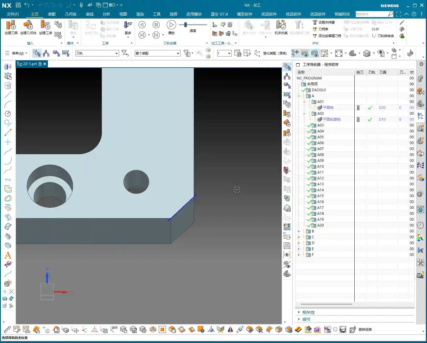
Locating the “Part Boundary” Function
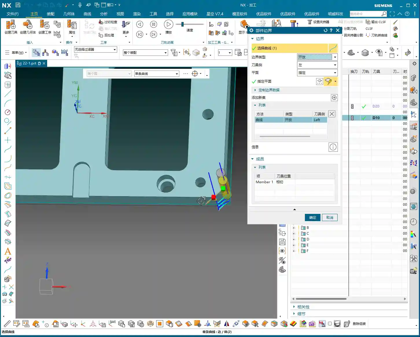
Double-click your planar profile milling operation and find the “Part Boundary” option. Click it, and you’ll see the machining boundary lines currently selected for your operation. Initially, the program might only have one selected; for clarity, we can select a few more. In the list, clicking any line will cause it to highlight.
Activating the “Trim and Extend” Function
Once you’ve selected and highlighted a specific line in the “Part Boundary” list, you’ll notice a new function appears below: “Trim and Extend.” Pay attention: this function only activates when a line is selected and highlighted; otherwise, you’ll be looking for it forever. Many newcomers get confused here.

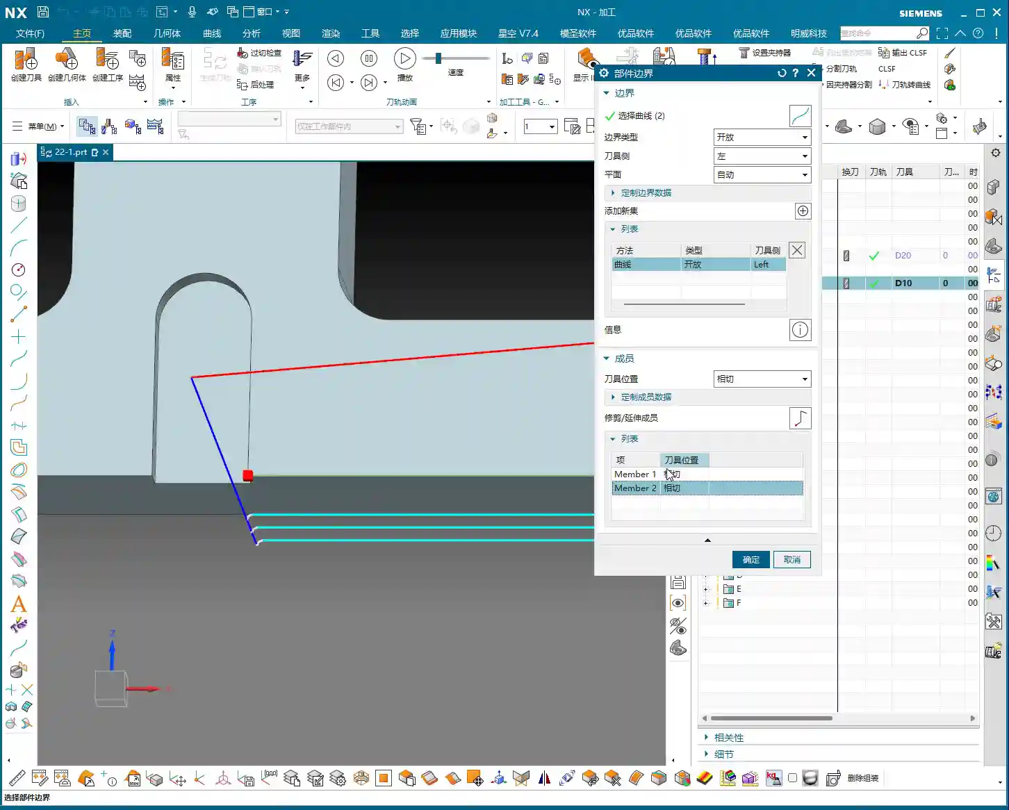
Hands-on Operation: Precisely Extending Boundary Lines
After activating “Trim and Extend,” you’ll see a circle. This circle is what you use to control extension or trimming. You can:
- Directly Drag: Just like dragging a line segment in CAD, pull the circle outwards to extend the toolpath; pull it inwards to trim the toolpath.
- Enter a Value: Directly input the desired extension or trim amount into the input box, for example, “2” mm. After confirming, the toolpath will follow your command.
Remember this: the extension amount cannot be too small. If it’s too small for the tool to effectively engage, the machine will alarm out! This function allows you to extend or trim the toolpath without modifying the original geometry, so the program certainly won’t “turn red.” Talk about peace of mind!
Tool Offsetting Selection: The Difference Between “Tangent” and “Open”
Next to “Trim and Extend,” you’ll also see a “Tool Position” option, with two important choices: “Tangent” and “Open.”
- Tangent: This means the tool will cut along your selected boundary curve, either on the outside or inside, while remaining tangent to the curve. This is the most common method, ensuring machining accuracy and surface quality.
- Open: This essentially means “Trace”, where the tool center will directly follow the curve you’ve selected. It’s typically used for special machining scenarios, such as when you need the tool’s centerline to strictly follow a path, or in certain roughing operations. But be careful! This means the tool will cut directly on your boundary line. If you haven’t left any stock, your part will be scrapped!
Don’t mix these two up. In real-world machining, especially for finishing passes, “Tangent” is your go-to option.
Customized Cutting Parameters: Making Every Edge “Obey”
Beyond extending and trimming, we can also apply individual parameter control to each machining boundary line. This function is a true gem when dealing with complex parts!

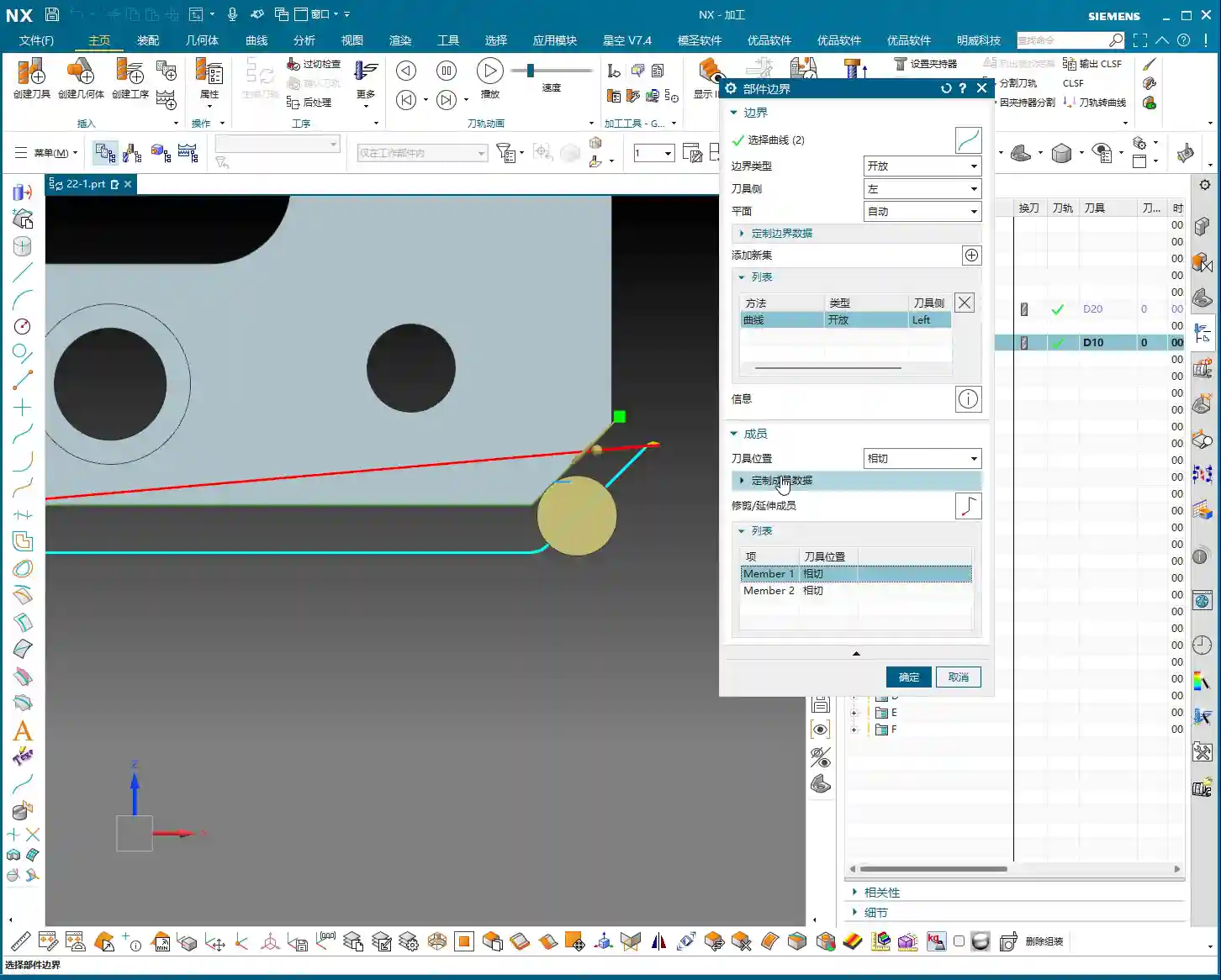
Understanding “Customize Member Data”
Within the “Part Boundary” function, select the line you want to adjust, then click “Customize Member Data.” Once this option opens, you’ll see the unique parameter settings for that specific line.
Stock Control: Fine-Tuned to Each Machining Line
The most important setting here is “Stock.” Normally, the stock we set applies globally to the entire operation. But here, you can set an independent stock value for each individual line. For example, if you have two boundary lines, one needs 10 mm of stock for roughing, and the other only 1 mm for a finishing pass, you can precisely control that here. This is a game-changer when machining asymmetrical or complex parts, or when you need multi-step finishing. Don’t underestimate these few millimeters of stock; they determine the machining difficulty and accuracy for your next operation!
Tolerance and Feed Rate: The Value of Individual Adjustment
Besides stock, you also have “Tolerance” and “Cutting Feedrate” here. While in practice we usually only manage stock, understanding these options gives you more tools to handle special situations. For instance, if a specific boundary segment requires higher precision, you can reduce its tolerance; if a segment experiences a heavy cutting load, you can even adjust its feed rate individually to ensure machining safety and extend tool life.
However, newcomers, you must distinguish that these parameters apply only to the currently selected line, not to the entire operation! Mess this up, and once the program runs, your part is scrapped. It’s simply not worth it.

Master Wang’s Experience: Boundary Universality in Planar Milling vs. Planar Profile Milling
Today, we’ve focused primarily on planar profile milling, but I want to add that the logic behind many functions in NX is interconnected.
Functional Interface Consistency
If you open the Planar Mill operation and look at its parameters for boundary extension, trimming, and alignment, you’ll find they are almost identical to those in planar profile milling. The functions, methods, and values are all the same. This indicates that when Siemens NX designed these commands, universality was considered, making it convenient for us machinists.
Distinguishing Application Scenarios
So, if they’re so similar, why differentiate between planar milling and planar profile milling? It’s simple:
- Planar Mill: Typically used for roughing or machining flat areas, focusing on efficiency and material removal.
- Planar Profile Mill: It excels at machining sidewalls and profiles. It can perform a finishing pass (for side walls) or even roughing on sidewalls. It requires more precise boundary control to ensure the final profile shape and surface quality.
Therefore, although the functions are similar, in practical application, you must choose the appropriate command based on your machining goals and workpiece characteristics. Using the right command gets the job done efficiently; using the wrong one often leads to rework or scrapped parts.
Summary: A Guide to Avoiding Traps
- **Prioritize Internal Program Boundary Control**: Don’t easily modify the original sketch; avoid parametric chaos and “red programs.”
- **Arc Tool Entry is King**: Especially for finishing passes and difficult-to-machine materials, arc tool entry effectively protects the tool and improves surface quality.
- **Differentiate Between “Tangent” and “Open”**: For finishing passes, choose “Tangent.” Unless you have a specific requirement, do not use “Open” – it will scrap your part!
- **Make Good Use of “Customize Member Data”**: Set different stock allowances for different boundary lines to achieve precise machining and enhance process flexibility.
- **Understand Universality vs. Specificity**: While many function interfaces are similar, be clear about each command’s actual application scenario; don’t misapply them.
Alright, that’s all for today. These are the real skills I, Master Wang, have painstakingly developed over fifteen years on the shop floor. I hope you can digest this well and avoid unnecessary detours! See you next time!
👤 About the Author:
The author is a veteran CNC machining professional with 15 years of industry experience, specializing in UG NX programming. This article is an original work representing personal practical insights.
⚠️ Copyright Notice: Unauthorized reproduction or distribution without prior communication is strictly prohibited.
Leave a Reply