📝 Key Takeaways: Master Wang’s personal secrets for Siemens NX Side Milling Head programming: The core is a “two-step” strategy. A detailed explanation of Tool Axis and Clearance Plane settings to avoid chatter and unnecessary air cuts. From Coordinate System setup to Roughing and Finishing, a step-by-step guide on how to efficiently and precisely machine complex groove parts. Move beyond pure theory and address real production challenges!
Hello everyone, I’m Master Wang. Last lesson, we thoroughly explored how to machine that workpiece below. This time, let’s dive into something more advanced – discussing 4-axis machining, specifically Side Milling Head programming.
Introduction: The ‘Two Key Skills’ of Side Milling Head Machining
Listen up, we’ll use this feature with a groove and specific geometry as an example, because it connects all the core technical points of the Side Milling Head. Don’t underestimate a simple groove; there’s a lot of knowledge involved.
Coordinate System Setup: The Absolute Foundation
Before starting any work, the first step is always to correctly set up the Work Coordinate System (WCS). This is a fundamental rule in NX programming and the lifeblood of our machining operations. If your WCS is incorrect, everything else will be pointless.
“Once you’re in the manufacturing module, make sure the coordinate system is set. Typically, we place it above the part’s datum face (bottom face), with the machining surface as the zero point. The Z-axis zero point is the part surface itself; this ensures dimensional accuracy. Don’t slip up! I just accidentally clicked into the properties, wasting time!”
The XYZ axis directions, especially the Z-axis, must align with your design intent and actual fixturing. This is fundamental and cannot be overlooked.

Practical Exercise One: Roughing Techniques for Floor and Wall Milling
Programming for a Side Milling Head isn’t vastly different from our usual 3-axis programming approach. The main distinctions lie in post-processing and the setup of a few specific parameters. Don’t rush, let’s take it step by step.
Floor and Wall Milling Operation and Initial Toolpath Generation
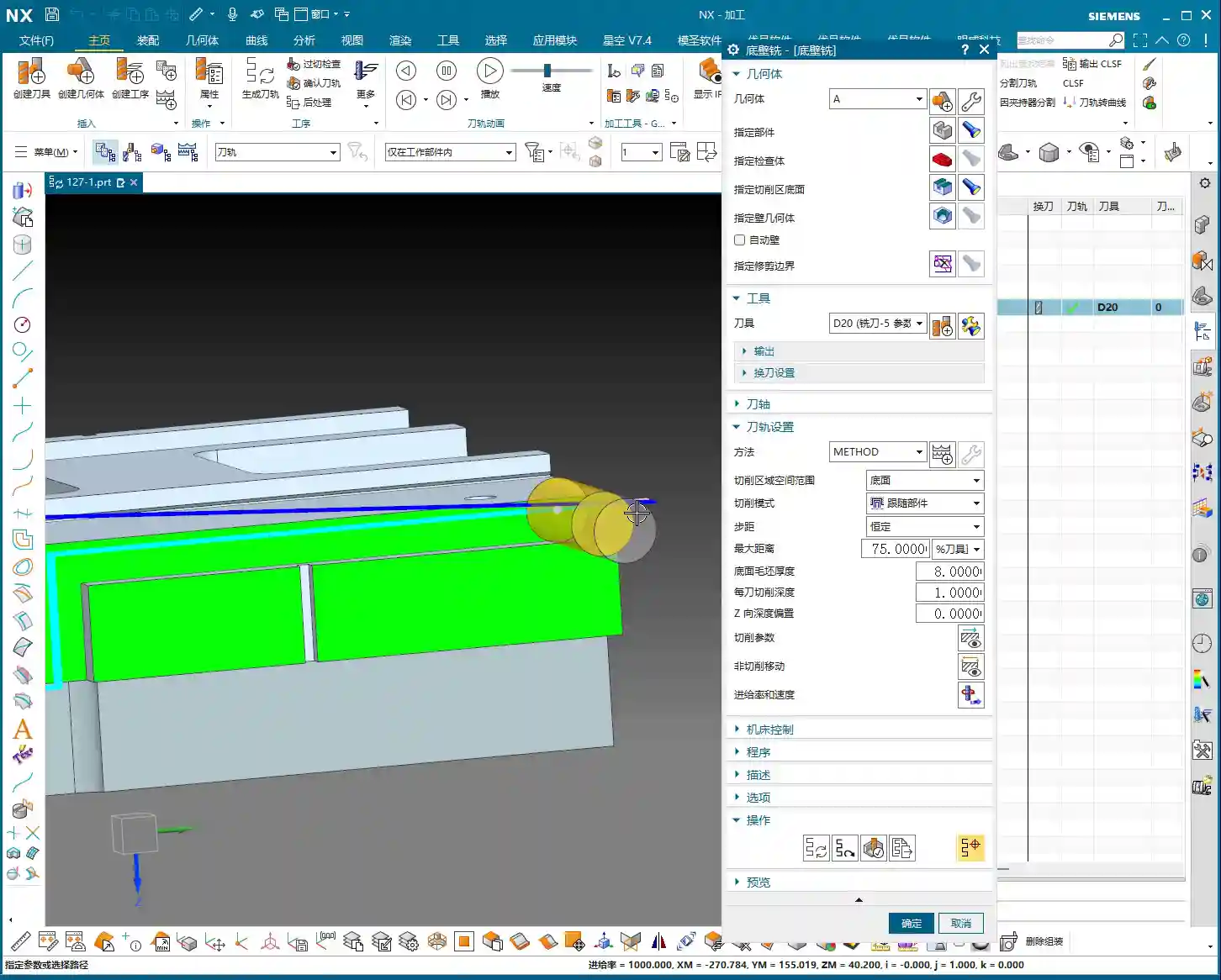
“Insert an operation; we’ll start with Floor and Wall Milling to rough out this groove feature. Let’s assume the bottom surface has already been milled, and we’re starting from the side. We’ll also assume the blank surface is flat to skip some initial preparation details.”
Let’s measure the depth of this groove first; it’s 8 mm. Therefore, select this side face for material removal and set the machining depth accordingly. For the tool, let’s just pick one for now, say a D10 end mill. Today’s focus is how to program for the Side Milling Head; we’ll delve into tool selection later.
“Just click generate and take a look. See that? The toolpath goes back and forth; it’s inefficient and results in a poor surface finish. This is exactly what we need to optimize!” While this back-and-forth ‘zigzag’ cutting might be acceptable in some situations, for Side Milling Head operations, especially for grooves, one-way cutting (climb or conventional milling) is the superior approach.
There’s another issue: once the program generates, observe the approach and retract moves. They lack smooth entry and exit. This is a major no-no in actual machining; directly plunging into the material can lead to chatter or even tool breakage, and it degrades the workpiece surface quality!

Core Secret: The ‘Two-Step’ Strategy for Side Milling Head Programming
To program effectively for a Side Milling Head in NX, just remember these two tricks—they’re practical know-how you won’t find in textbooks.
Trick One: The Key to Clearance Plane Setup
“In our usual 3-axis machining, the clearance plane is always above the workpiece to prevent collisions. But with a Side Milling Head? It’s working from the side! Therefore, the Clearance Plane must change accordingly.”
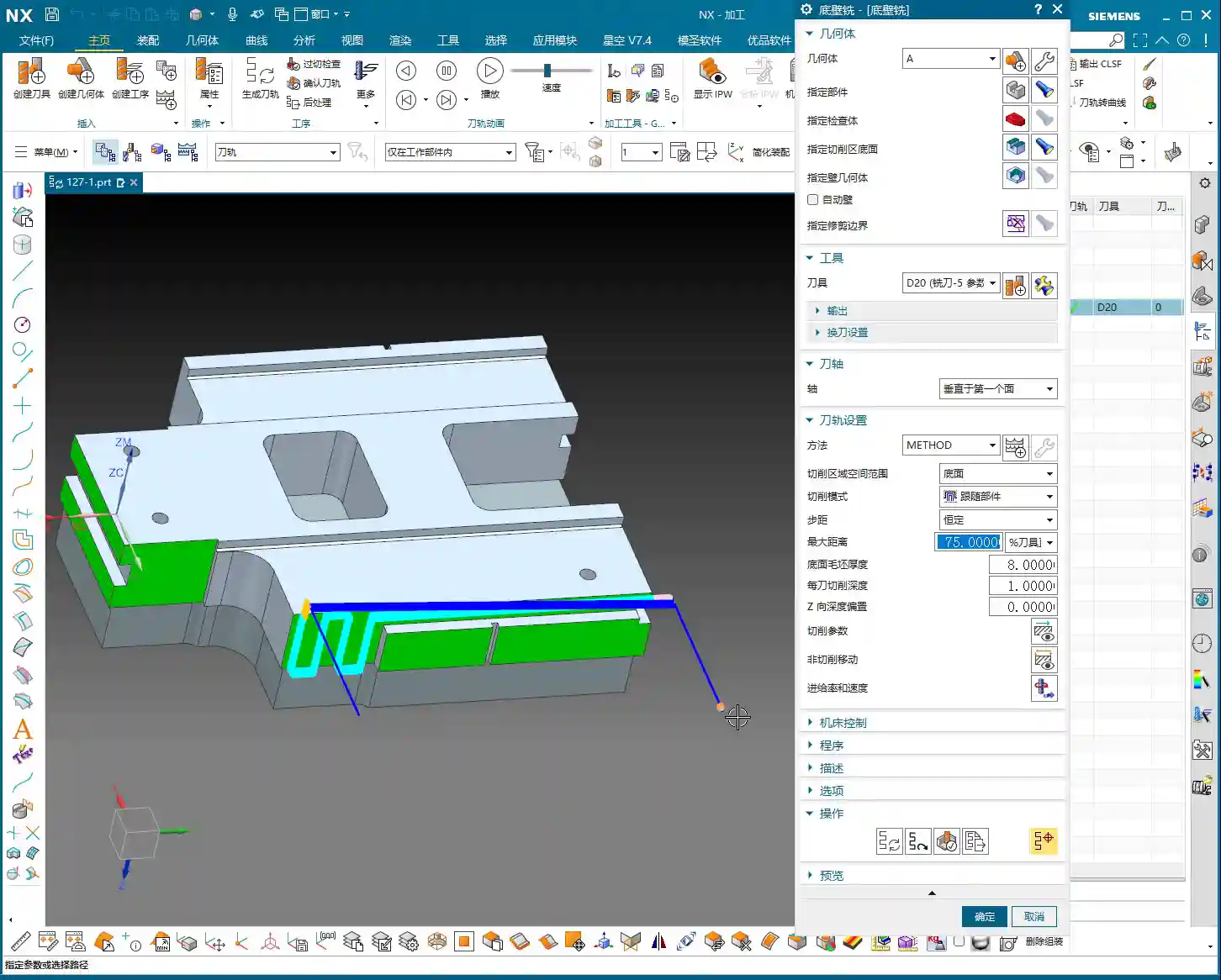
Go into the “Non-Cutting Moves” options and find “Clearance Settings”. Change the original “Automatic” or “Distance” setting to “Plane”. Then, here’s the crucial part: designate your clearance plane as the side face of the machining surface, and adjust the offset direction and distance. This way, during rapid moves, the tool will safely retract from the side instead of lifting high up and then coming back down, which both improves efficiency and prevents collision risks.
“For operations like Floor and Wall Milling, just adjusting the clearance plane is enough, as its tool axis is by default perpendicular to the bottom face. However, for other operations like Planar Profile and Depth Profile, you’ll need to use the second trick.”

Trick Two: Precise Control of Tool Axis Direction
This is the essence of Side Milling Head programming! “If the Tool Axis direction is incorrect, the program simply won’t generate, or it will behave erratically if it does. Don’t just rely on software simulations; observe the cutting sparks!”
For Side Milling Head operations other than Floor and Wall Milling, the tool axis might still default to the Z-axis direction, which is incorrect. We need to go into the “Tool Axis” settings:
- Select “Specify Vector”.
- Then choose “Fixed” or “Automatic Detection”. The most reliable method is to directly select the specific side face you intend to machine.
- The software will automatically adjust the tool axis direction to be perpendicular to the selected side face.
“Once this is changed, the tool will know which direction to cut. Combined with linear approach and retract moves, for instance, using 60% of the tool diameter as the entry length, the cutting process becomes much smoother. This prevents direct tool impact on the workpiece, significantly extends tool life, and improves machining quality.”
Practical Exercise Two: Tool Axis Adjustment for Planar Profile and Depth Profile Milling
Alright, let’s switch locations and demonstrate again. This time, we’ll use Planar Profile and Depth Profile Milling, specifically for side walls.

Planar Profile Milling Case Study: Tool Axis Correction and Parameter Optimization
“Let’s measure this groove width; it’s 4 mm. So, we’ll directly use a 4 mm tool for roughing.”
Create a new “Planar Profile” operation, select the machining boundaries, bottom face, and so on. Tool D4, generate the program directly… “See? Still no good! It’s warning again that the ‘tool axis cannot be perpendicular to the bottom face.’ This is exactly what we discussed earlier—we need to change the Tool Axis!”
Open the “Tool Axis” settings, change it to “Specify Vector”, then select “Automatic Detection”, and finally, the crucial step: click on the side wall plane you intend to machine! “This way, the tool understands its direction is towards the side.”
Once the tool axis is corrected, the program can generate smoothly. Don’t forget to optimize the cutting parameters:
- Stepdown: 0.2 mm.
- Cutting Method: Mixed Cut.
- Stock: 0 (if this is a Finishing pass).
- Approach/Retract: Linear approach, 60% of tool diameter, Retract is 0.
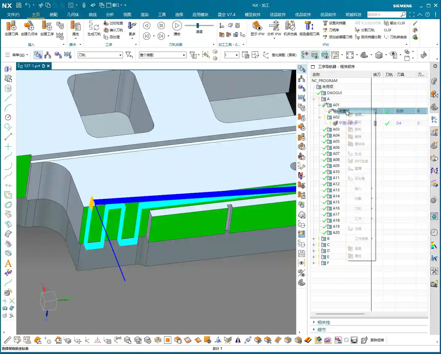
Finally, don’t forget to also change the Clearance Plane to the side. This way, your entire Side Milling Head roughing program will be solid. If you need a Finishing pass, simply copy and paste the program, set the stock to zero, and recalculate; you’ll get it done quickly.
Depth Profile Milling Case Study: Non-Standard Tools and Approach/Retract Optimization
Let’s look at another example with Depth Profile Milling. “I measured this area, and it has a dimension of 10.1 mm. This isn’t a standard tool size! We can only use a D10 tool, leaving a small amount of stock, and then follow up with a Finishing pass.” This is a practical situation in production—you can’t just customize a tool for every non-standard dimension, can you? The cost won’t allow it!
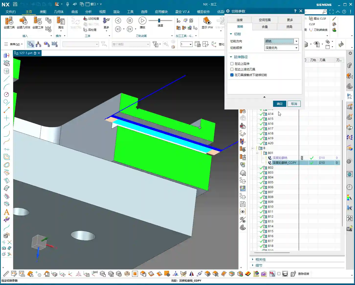
For the operation, select “Depth Profile Milling” and for the cutting method, choose “Center” (which makes the tool center follow the boundary). With the initial settings, the tool axis is still Z-directional, and the program won’t generate. “It’s the Tool Axis problem again! Same old issue.”
Just like before, change the tool axis to “Specify Vector”, select “Automatic Detection”, and then click on the side wall plane. The program will then generate normally.
Then, for optimization:
- Cutting Method: Mixed Cut, for a more even toolpath.
- Approach/Retract: Linear, 60% of tool diameter, Retract is 0.
- Stock: 0.05 mm (to leave material for Finishing pass).
Finally, check and set the Clearance Plane, ensuring it’s on the side. With that, your Depth Profile Milling program is also sorted.
Summary: Pitfall Avoidance Guide
Alright folks, listen up! The core of Side Milling Head programming boils down to these two points. Master them, and you’ll save a lot of detours and prevent many tool crashes:
- Tool Axis Direction: This is the soul of Side Milling Head programming. Except for a few operations like Floor and Wall Milling where the tool axis is automatically determined, for any other side machining operation, you must manually specify the tool axis direction. Select “Specify Vector,” then click on the side face you are actually machining, so the tool cuts perpendicular to that face. This is crucial for preventing the tool from “crashing into the wall”!
- Clearance Plane: A Side Milling Head operates from the side, so its clearance plane should also be on the side. In “Non-Cutting Moves,” ensure you change the clearance settings to “Plane” and designate a side face parallel to the machining surface as the clearance plane. This allows the tool to safely approach and retract, avoiding unnecessary lifts and air cuts, thereby boosting overall machining efficiency.
- Approach/Retract Settings: To ensure stable cutting and extend tool life, always set the approach and retract moves to linear or arc transitions. Also, set an appropriate entry distance (e.g., 60% of the tool diameter) to prevent the tool from directly impacting the workpiece.
- Handling Non-Standard Dimensions: When encountering non-standard dimensions like 10.1 mm, don’t think about customizing a tool. Prioritize using a nearby standard tool (e.g., D10), and resolve the issue by leaving stock and performing a secondary Finishing pass. This is the most cost-effective approach.
Remember these practical tips, and you’ll get fewer reprimands and produce more in the workshop! Don’t just rely on software simulations; go to the machine, observe the cutting sparks, and listen to the cutting sounds – that’s where the real skill lies!
👤 About the Author:
The author is a veteran CNC machining professional with 15 years of industry experience, specializing in UG NX programming. This article is an original work representing personal practical insights.
⚠️ Copyright Notice: Unauthorized reproduction or distribution without prior communication is strictly prohibited.
Leave a Reply