📝 Key Takeaways:
Practical Guide to Siemens NX Cavity Milling Cutting Patterns
Listen up, folks. I’m Old Wang, Master Wang. Today,…
Listen up, folks. I’m Old Wang, Master Wang. Today, we’re not mincing words. I’m going to break down and clarify all those cutting patterns in Siemens NX Cavity Milling. You won’t learn this stuff from books; it’s all from getting your hands dirty at the machine, watching the chips fly, and figuring things out.
Cavity Milling: The Foundation of Intelligent Roughing
Cavity Milling is our workhorse for machining deep, complex cavities. It’s incredibly smart and can save you a lot of hassle, but only if you understand how it operates.
Quick Generation and Initial Validation
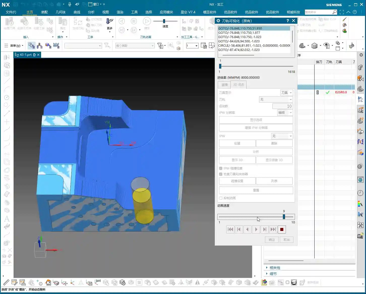
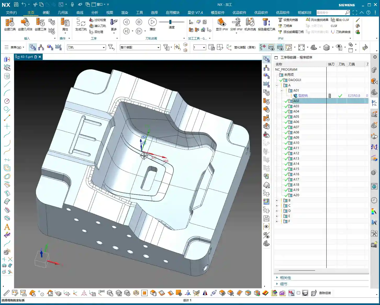
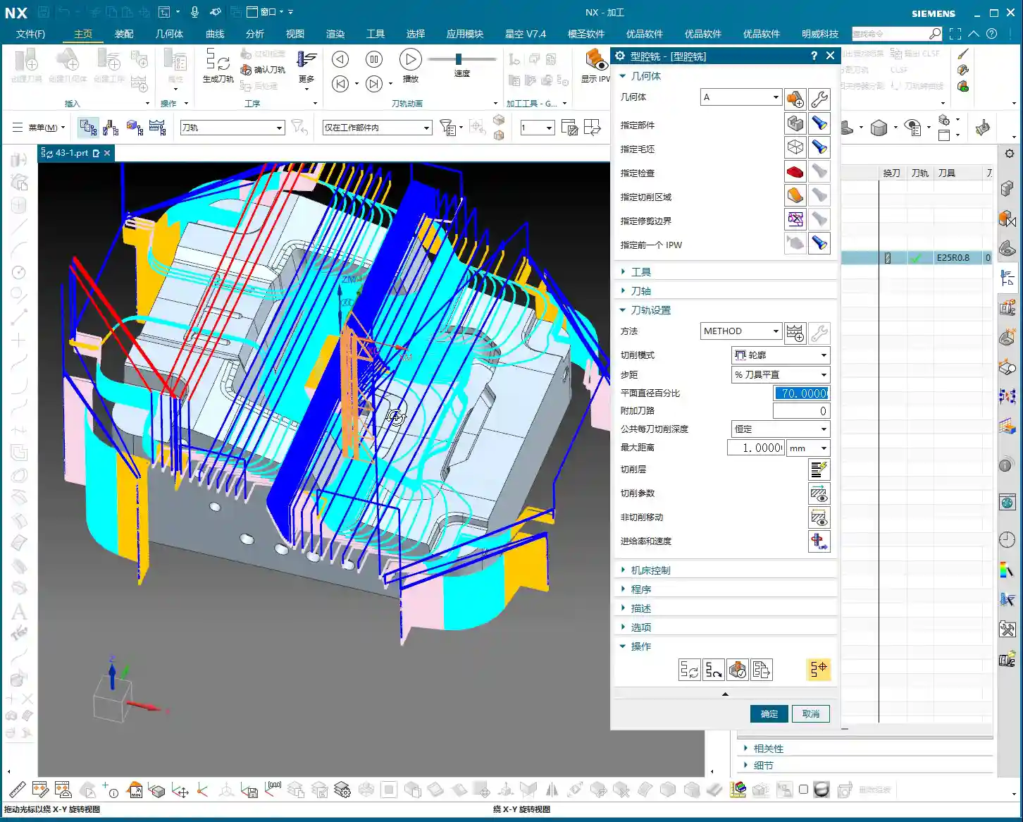
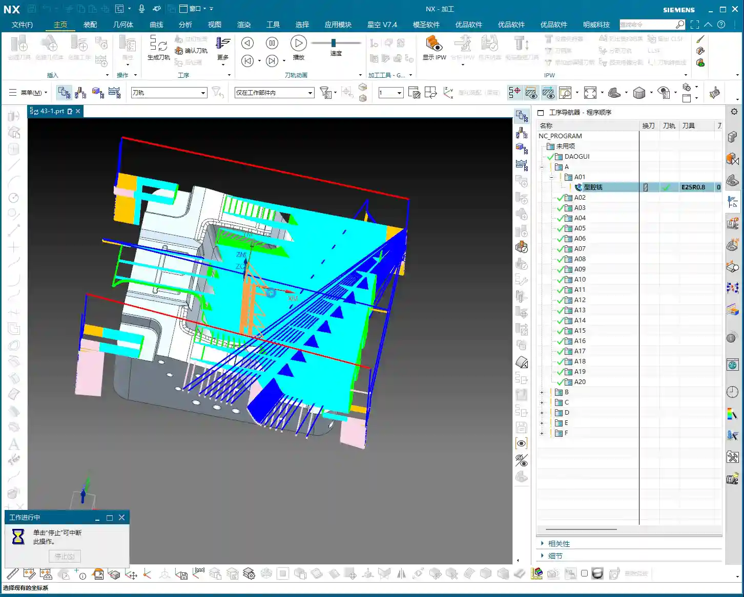
Typically, when I program, especially for roughing operations like this, I don’t overthink it at first. I just complete these three steps: Specify Part, Specify Blank, and Select Tool. Once those are done, the program is generated. After it’s generated, we can then take our time to fine-tune it.
You see, I usually generate the program within about three to five steps. For operations like “Cavity Milling,” “Floor and Wall Milling,” or “Planar Milling,” these three steps typically get the job done. Once the program is generated, we click “Verify Tool Path,” run it with “3D Dynamic,” and get a general idea of the tool path. Don’t rush; take your time. Don’t just look at the software simulation; visualize the chips flying and clearly understand how the machine will move.

Siemens NX Cavity Milling’s Intelligent Recognition: Open vs. Closed Regions
Many young guys ask me, “Master Wang, when we learned Planar Milling or Floor and Wall Milling, we needed a pre-machining step before simulation, right? Why isn’t that needed for Cavity Milling?” Listen up, that’s where Cavity Milling’s intelligence comes in!
Because when you set it up, you’ve already specified your blank. It can automatically determine whether a region is “open” or “closed.”
- If the tool enters from outside the blank, it’s an open region.
- If the tool must plunge into the blank from within, it’s a closed region.
NX automatically identifies this and generates the most suitable tool path based on the region’s characteristics. This isn’t just randomly generated; it’s what the software “considers reasonable.” So, don’t underestimate this software; often, it’s more thorough than you young newcomers might think.
A Veteran’s Essential Advice: Tools and Rest Material
No matter how smoothly your program runs, if you choose the wrong tool, it’s all for nothing! That’s a lesson learned the hard way.

Tool Selection is Key: The Lesson of the Large Tool in a Small Slot
We just finished the simulation, did you notice a problem? Look at that small slot—why wasn’t it machined? Logically, if the program was generated, it should have been machined!
The problem is right here: you’re using a D25R0.8 tool. Now look at that slot, how wide is it? 10mm!
Listen up: how can a 25mm tool possibly machine a 10mm wide slot? Isn’t that clearly a case of “large tool, small slot”? The tool is wider than the slot; it simply cannot enter, so naturally, it can’t machine it. If the tool can’t cut here, it won’t be able to machine further down. Otherwise, you’re just asking for an overcut or a crash!
So, when you see an area that hasn’t been machined, don’t immediately blame the software. First, check if you’ve selected the wrong tool! That’s fundamental common sense.
Secondary Roughing Strategy: The Secret Weapon for Detail Cleanup
So, what about those areas where the large tool can’t reach? We can’t just leave rest material, can we?
This is where our “secondary roughing” comes in. While Cavity Milling might leave some unmachined areas during the initial roughing due to large tool size, it supports secondary roughing (or rest roughing). After the main roughing operation is complete, we can switch to a smaller tool to specifically clean up those corners, small radii, or narrow slots. This is an essential procedure for machining high-precision parts.
So, if there are areas left unmachined after the first roughing pass, don’t worry, it’s completely normal. This is to protect the large tool and allow it to efficiently handle the work it can do. Those intricate corners and tight spots, we leave for the secondary roughing to clean up.
In-Depth Analysis of Cutting Patterns

Cutting patterns are at the core of Cavity Milling. Choose correctly, and you’ll achieve twice the results with half the effort; choose incorrectly, and you might scrap the part or even crash the machine.
Reject Dogma, Start with Practical Application
In NX’s “Cutting Patterns” options, there are dozens of choices: “Follow Part,” “Follow Periphery,” “Profile,” “One-Way,” “Zig-Zag”… it’s dizzying. Some books explain them elaborately, but in practice, they might not work as advertised. We’ll focus on the most common and practical ones.
Follow Part and Follow Periphery
These are the two most common patterns for Cavity Milling, each with its own advantages.
- Follow Part: The tool path closely follows the shape of your part. The advantage is a relatively intuitive tool path, but the disadvantage is also very clear: there will be more retractions (air cuts). Especially in areas with complex shapes, it frequently retracts to conform to the part contour, which inadvertently increases machining time and reduces efficiency.
- Follow Periphery/Boundary: The tool path moves in concentric loops along the outer boundary of the machining area, either inward or outward. Its main characteristic is fewer air cuts (retractions) and better tool path continuity. For materials like aluminum or those with less stringent cutting force requirements, this pattern often leads to higher machining efficiency. It allows the tool to maintain continuous cutting as much as possible, reducing unnecessary engagements, disengagements, and retractions.
From the recent demonstration, for our aluminum part, Follow Periphery is clearly much better than Follow Part. It has fewer retractions, and the tool path is more logical.

The Clever Use of Profile Mode
The “Profile” mode, as its name suggests, only machines the contour of the part. So, is it useless? Absolutely not!
Of course, it’s not suitable for hollowing out a deep cavity from a large block of raw material; that would be too slow and prone to problems. However, if your part is a casting or forging that is already very close to its final shape, and only requires removing a small amount of material from a single side, or just a single roughing pass with a large tool, then the “Profile” mode is highly efficient. It can quickly trace the part’s exterior, removing excess material without generating air cuts. So, don’t generalize; you need to consider the state of your blank.
Warning Against Inappropriate Patterns: One-Way, Zig-Zag
NX also has “One-Way” and “Zig-Zag” patterns, but for cavity roughing, these two modes are generally unsuitable in most situations.
- One-Way: This tool path pattern causes frequent retractions. After each cutting pass, the tool retracts back to the starting point to plunge again. This is extremely inefficient, it’s just “ridiculous”! Machining time will double with no real benefit.
- Zig-Zag: While it has fewer retractions than One-Way, for complex cavities, it still generates many unnecessary air cuts and redundant paths, making it also unsuitable for efficient roughing.
Therefore, we generally don’t consider these two patterns for Cavity Milling. They might have their uses in other machining methods, but for cavity roughing, they are a waste of time.
How to Choose the Most Suitable Cutting Pattern?
Part Features Determine the Machining Strategy
Which cutting pattern is best? There’s no single answer. It mainly depends on your part’s features and the blank condition.
- If your part is being machined entirely from solid material, requiring significant material removal, then Follow Periphery and Follow Part are the primary choices.
- If your part is a near-net shape casting or forging, and only requires removing a small amount of material from one side or refining the exterior, the Profile mode might be more efficient.
Efficiency First: Focus on Air Cuts and Machining Time
If you’re really unsure, then I’ll teach you the most practical method: Generate both and compare!
Go ahead and generate one program using “Follow Part,” then another using “Follow Periphery.” Then, run a simulation for both. See which program has fewer retractions (fewer air cuts), which has a shorter total machining time, and which looks like a smoother tool path, better suited for your part. That’s the one you should use. This is the most direct and reliable way to decide.
Remember, NX is just a tool. Ultimately, it must serve your machining efficiency and cost control. Don’t be fooled by flashy theories; real-world testing and comparison are key.
Summary: Pitfall Avoidance Guide
- Tool and Size Mismatch: Always remember, a large tool cannot machine small features. If you see rest material, first check if the tool diameter and corner radius can enter the area.
- Rest Material Management: It’s normal for initial roughing not to remove all rest material. Don’t force the first roughing pass to clean everything; use secondary roughing (with a smaller tool) to address it.
- Cutting Pattern Selection:
- For roughing from solid material: Follow Periphery and Follow Part are preferred. In practice, Follow Periphery often reduces air cuts and increases efficiency.
- For near-net shape castings/forgings: Consider the Profile mode for single-side material removal.
- Avoid One-Way and Zig-Zag patterns for cavity roughing; they are typically inefficient with excessive retractions.
- Practical Experience is Key: When faced with an uncertain cutting pattern, don’t hesitate to generate and compare. Use the one that has fewer air cuts and higher machining efficiency. Don’t just memorize theories; make your decisions based on the actual part and machine performance.
👤 About the Author:
The author is a veteran CNC machining professional with 15 years of industry experience, specializing in UG NX programming. This article is an original work representing personal practical insights.
⚠️ Copyright Notice: Unauthorized reproduction or distribution without prior communication is strictly prohibited.
Leave a Reply