📝 Key Takeaways: For the first operation programming of multi-sided angle heads, Master Wang emphasizes the flexibility of tool axis settings in NX programming, especially in 4-axis horizontal machining scenarios. The core lies in judiciously choosing Linear interpolation (G01) instead of Rapid move (G00) for tool path output to prevent tool collisions and maintain accuracy. Through roughing, secondary roughing (rest milling), and finishing passes for the bottom and side walls, he elaborates on optimizing retraction strategies and controlling stock allowance to ensure machining efficiency and part accuracy.
[VIDEO_HERE]
Listen up, lads. Today, Master Wang is going to walk you through a tough nut to crack – programming the first operation for a multi-sided angle head. Don’t let the name intimidate you; once you grasp the underlying principles, operating it in NX isn’t all that complex. I’ve been doing this for years, seen and heard countless machine issues. What I’m sharing are hard-earned practical experiences, not something you’ll pick up from a textbook.
Overview: Multi-Sided Machining Strategies and Tool Axis Definition
Commonalities Between 4-Axis Horizontal Machining and Angle Heads
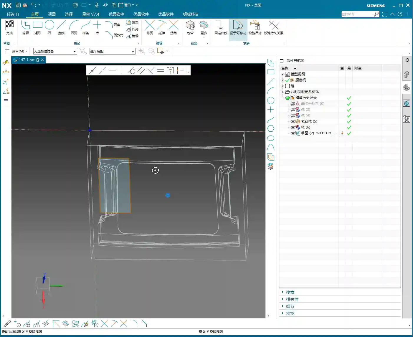
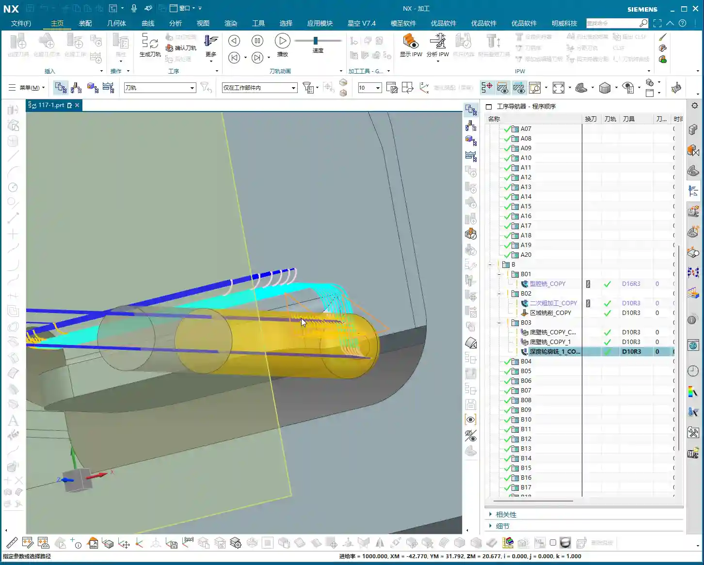
Typically, once we get a part and complete the process analysis, we can jump straight into programming. Machining with an angle head is quite similar in principle to 4-axis horizontal machining. It’s essentially about reorienting the tool axis. With a 4-axis horizontal machine, you can rotate the part to the desired angle for machining, which is very convenient. An angle head works on the same principle; it rotates the tool axis, allowing you to cut from the side. So, whether you’re dealing with an angle head or a 4-axis horizontal setup, the programming approach is the same. Don’t overcomplicate it; the core concept is tool axis transformation.
Remember this: any method that allows the tool to contact the workpiece in the right position and orientation is a good method. Don’t just stare at all the fancy features in the software; focus on how to get the job done efficiently and accurately on the machine.
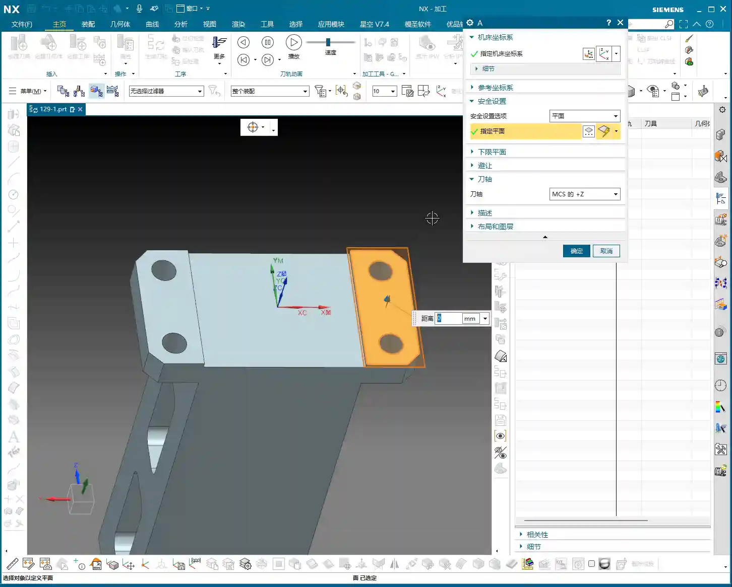
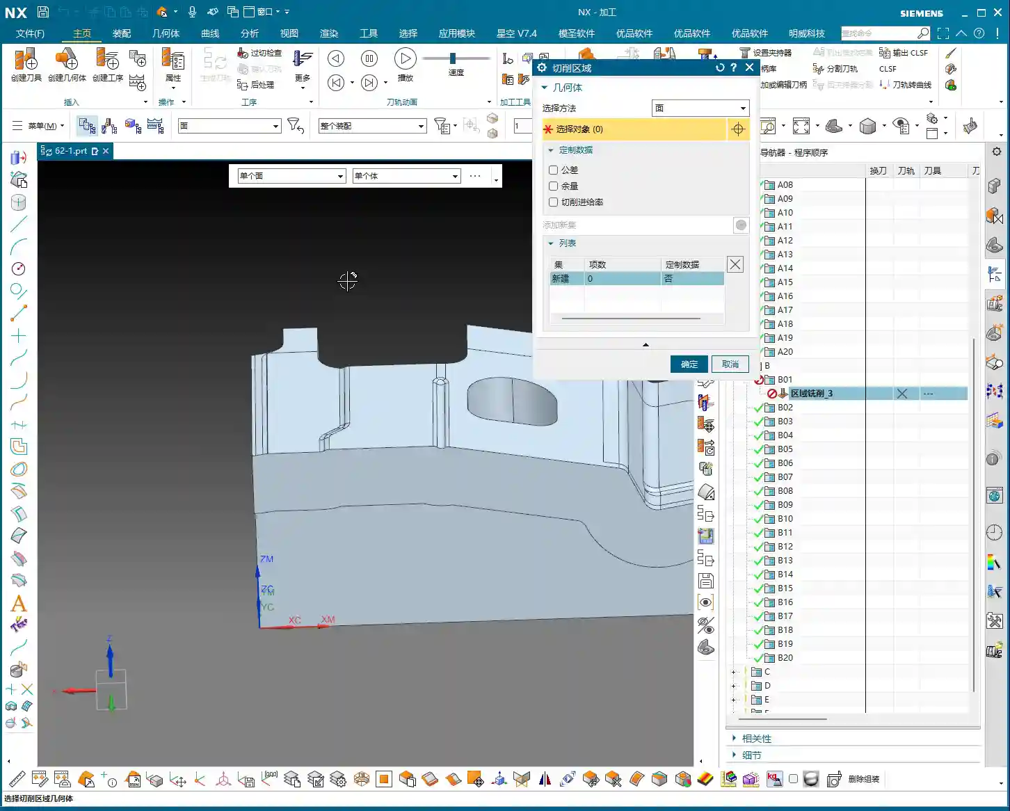
Flexible Specification of Tool Axis Direction
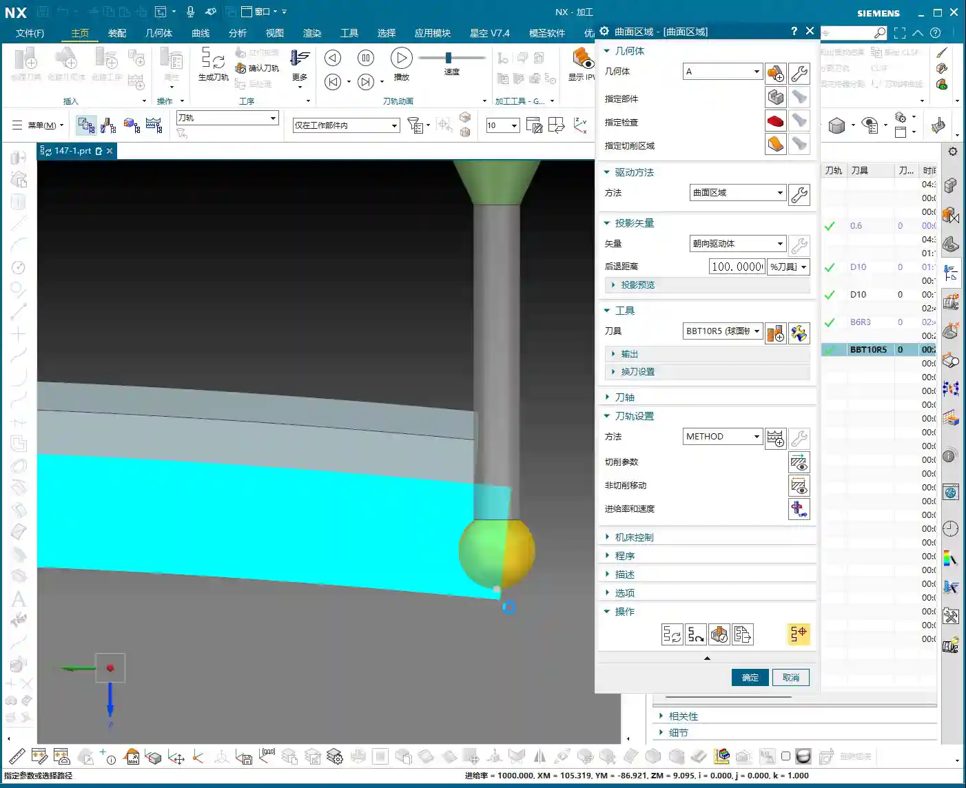
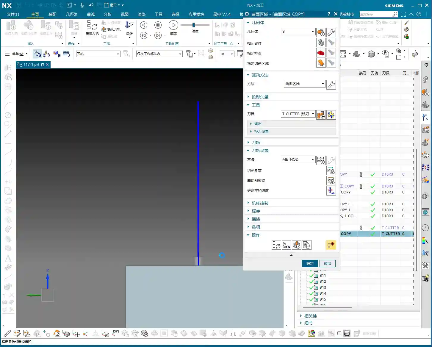
Specifying the tool axis direction here is crucial. In NX, when selecting the tool axis, you can let it automatically determine the direction, or more reliably, directly select the face you need to machine. For instance, if you’re machining a side face, just click that face, and NX will automatically adjust the tool axis to be perpendicular to it. This is the most direct and least error-prone method. It will orient the tool axis outwards, allowing us to cut along that face.
Don’t underestimate the tool axis direction; it directly impacts your tool’s cutting force direction, chip evacuation, and even determines whether you can successfully engage the cut. Especially when machining deep cavities or complex surfaces, precise control of the tool axis becomes exceptionally important.

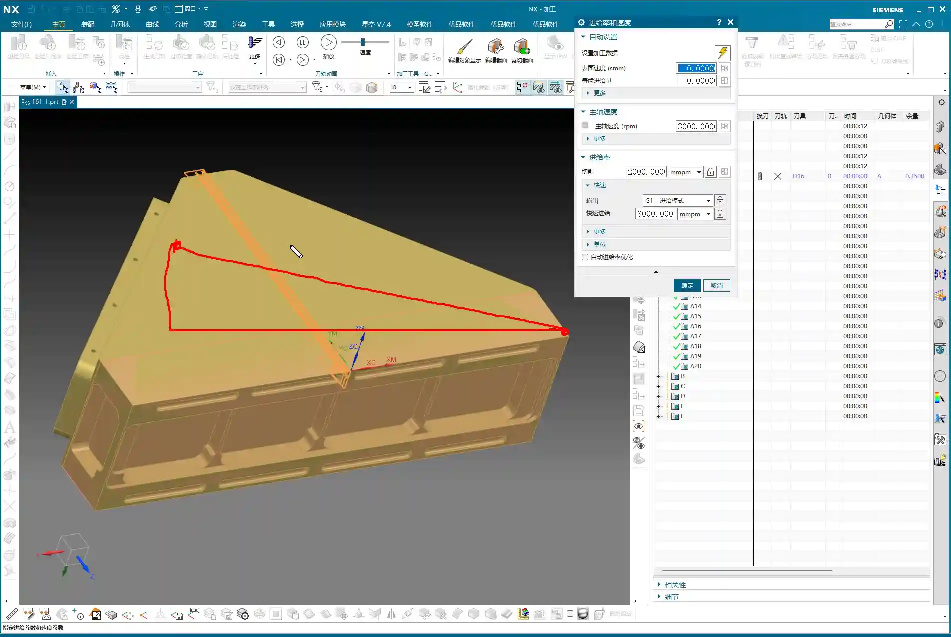
G-code Output Core Points: Linear Interpolation (G01) and Safe Movement
Eliminating the Rapid Move (G00) Trap: Enforcing Linear Interpolation (G01)
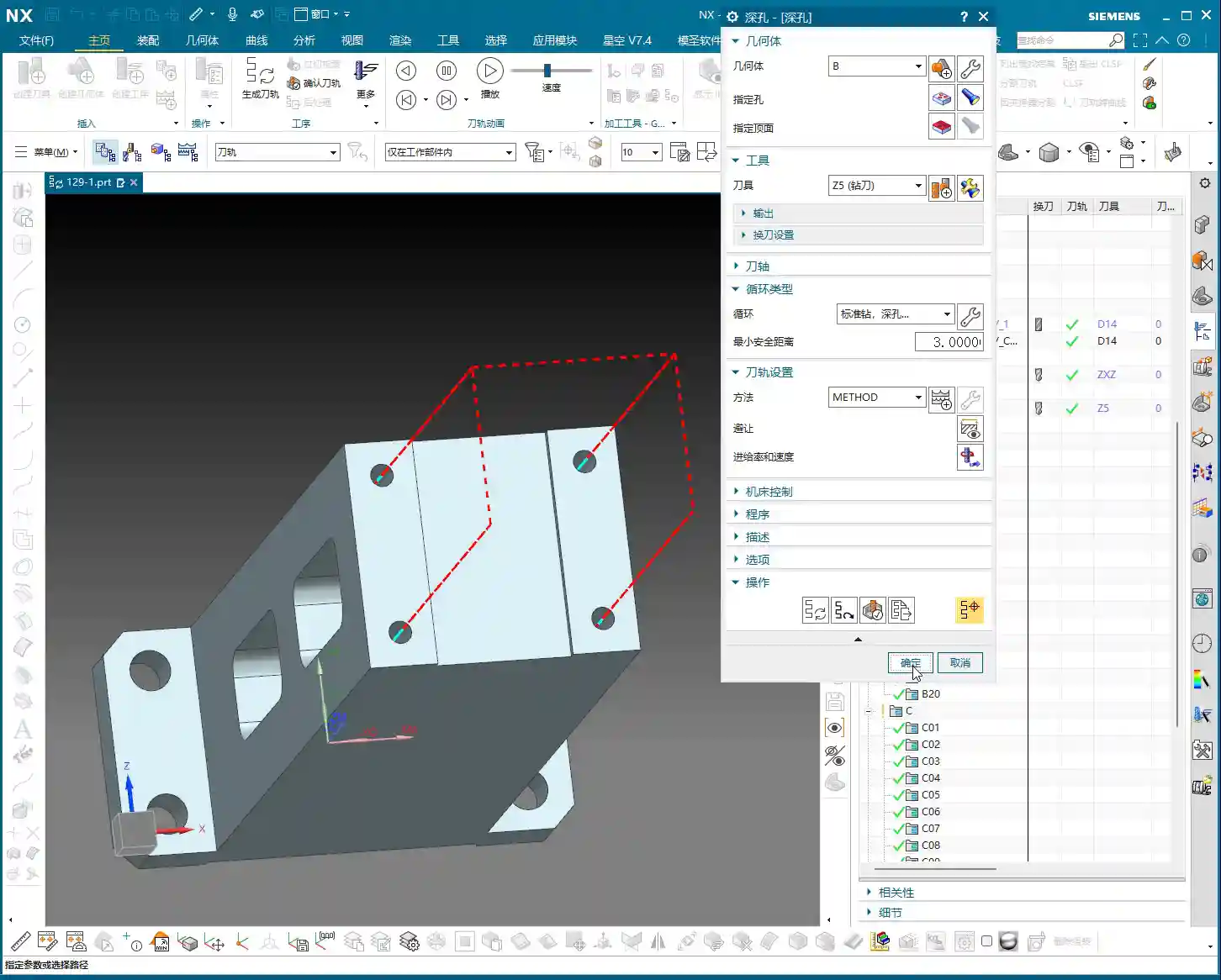
Listen up! This is what Master Wang wants to emphasize, and textbooks might not tell you this in such detail. In NX programming, especially concerning rapid moves, it’s best, and in fact, essential, to output them using Linear interpolation (G01), not Rapid move (G00)! Why?
Because some machine tools, especially older ones, don’t necessarily move in a straight line during a Rapid move (G00). It might move X first, then Y, or Z first, then XY. This can result in a path that looks like “steps” or even takes a wide detour. Your software simulation might look perfect, but once it’s on the machine, you might end up with a hard collision – a tool crash! Even if it doesn’t crash, those sudden changes in speed and travel patterns can easily affect machining accuracy and surface finish. So, for safety and to ensure accuracy, we’ll universally output with Linear interpolation (G01). While it might be slightly slower, the significant increase in safety and stability makes it well worth it!
Post-Processor and G-code Behavior
I just mentioned that a Rapid move (G00) might take “steps,” and that’s actually related to your post-processor. Some post-processors, even if you set up rapid movements in NX, will still output Linear interpolation (G01) straight-line movements, which is perfectly fine. However, if your post-processor defaults to outputting Rapid move (G00), and your machine doesn’t execute Rapid move (G00) as a straight line, then you need to be careful. Therefore, always check your post-processor settings to ensure that all rapid movements (such as tool entry/retraction and air moves) are executed as Linear interpolation (G01) or at least as safe, straight-line Rapid move (G00). Don’t just rely on software simulations; you need to see how the actual G-code runs – that’s the real test.

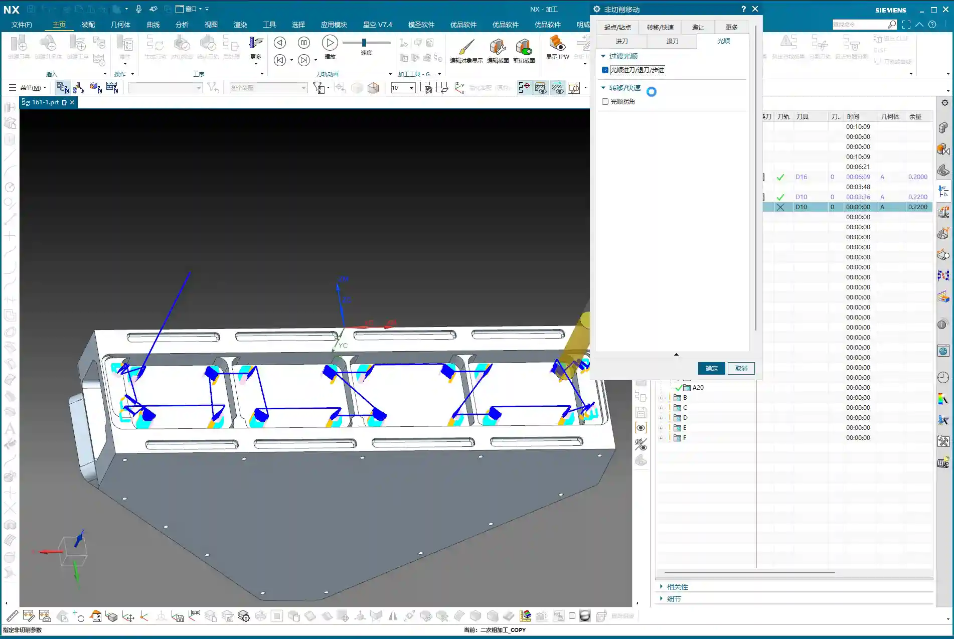
First Operation Roughing and Retraction Strategies
Optimizing Retraction Paths: Avoiding Unnecessary Movements
When we’re programming, there’s one area that often gets overlooked: tool retraction. I see a lot of younger guys setting up retraction paths that are far too long and straight; that’s just a waste of machine time! For example, if a retraction path is too long, we can shorten it or change it to an arc retraction. Say, in your entry/retraction moves, set the retraction to an arc with a radius of 1mm. This makes the tool exit more flexibly and effectively reduces air-cutting time. Don’t underestimate a few seconds here and there; over time, that adds up to significant savings for a machine in a year! So, make it as short as possible, use an arc if you can, be flexible, don’t be rigid.
Aluminum Roughing Parameter Settings
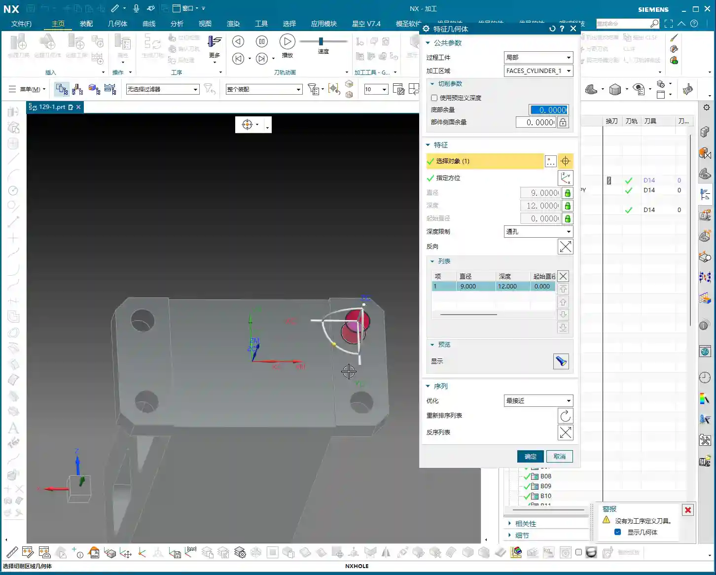
Let’s assume we’re machining aluminum this time; aluminum is relatively soft and easy to machine. When roughing, tool selection is also critical. We’ll typically choose a larger tool, such as a D16 (16mm diameter) end mill, to quickly remove most of the material. The tool axis direction must be correctly specified, ensuring it’s perpendicular to the side face being machined. Feed rates and spindle speeds should be determined based on the tool, material, and machine capabilities; don’t blindly chase speed. Ensure smooth chip evacuation to prevent chip buildup. The stock allowance should also be set according to the actual blank dimensions; don’t let the tool take too heavy a Depth of Cut (DOC) right at the start, as this can easily cause chipping.

Secondary Roughing and Finishing Strategies: Smoothing and Accuracy
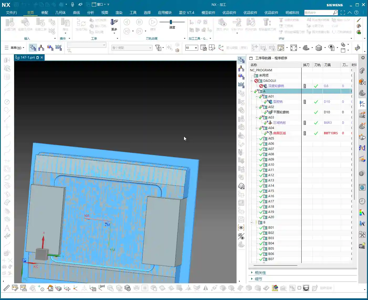
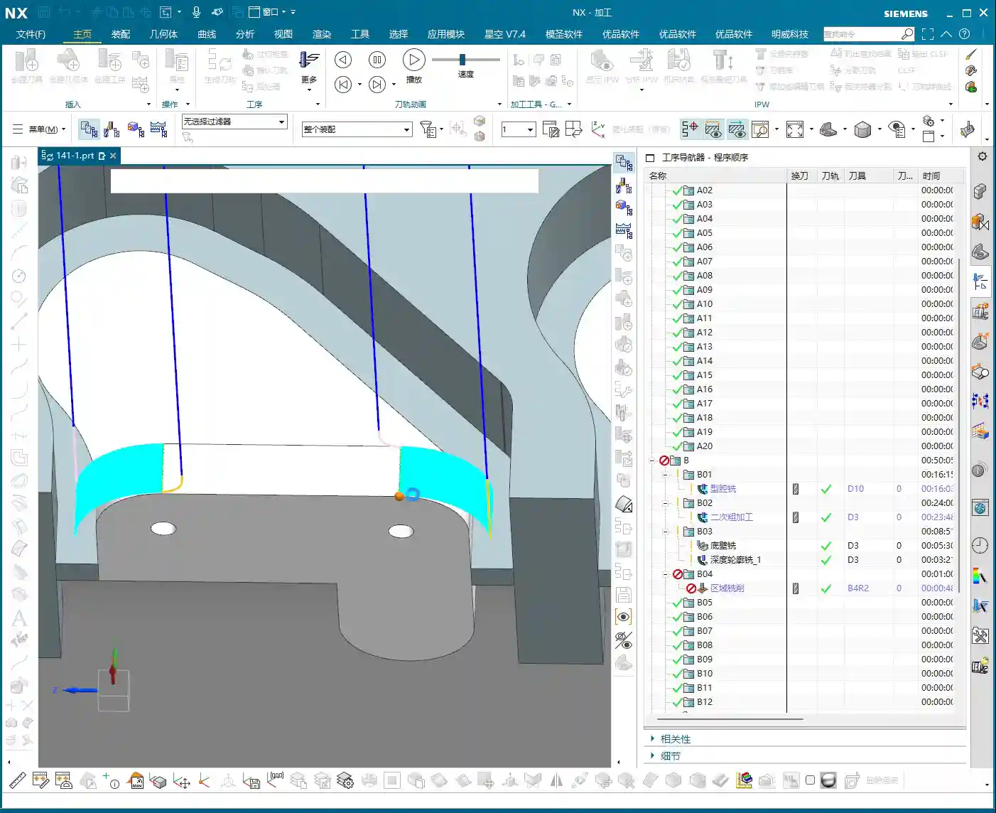
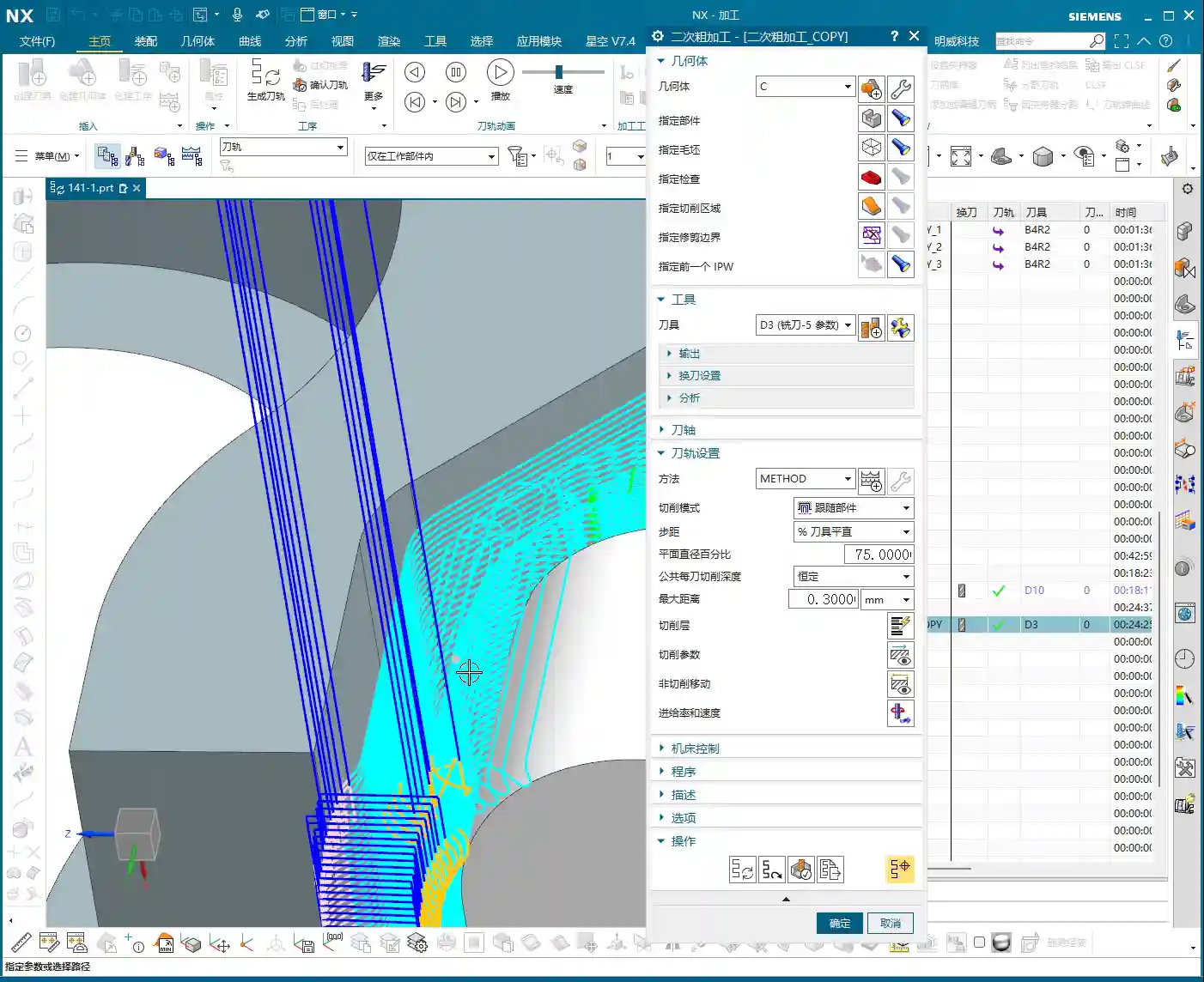
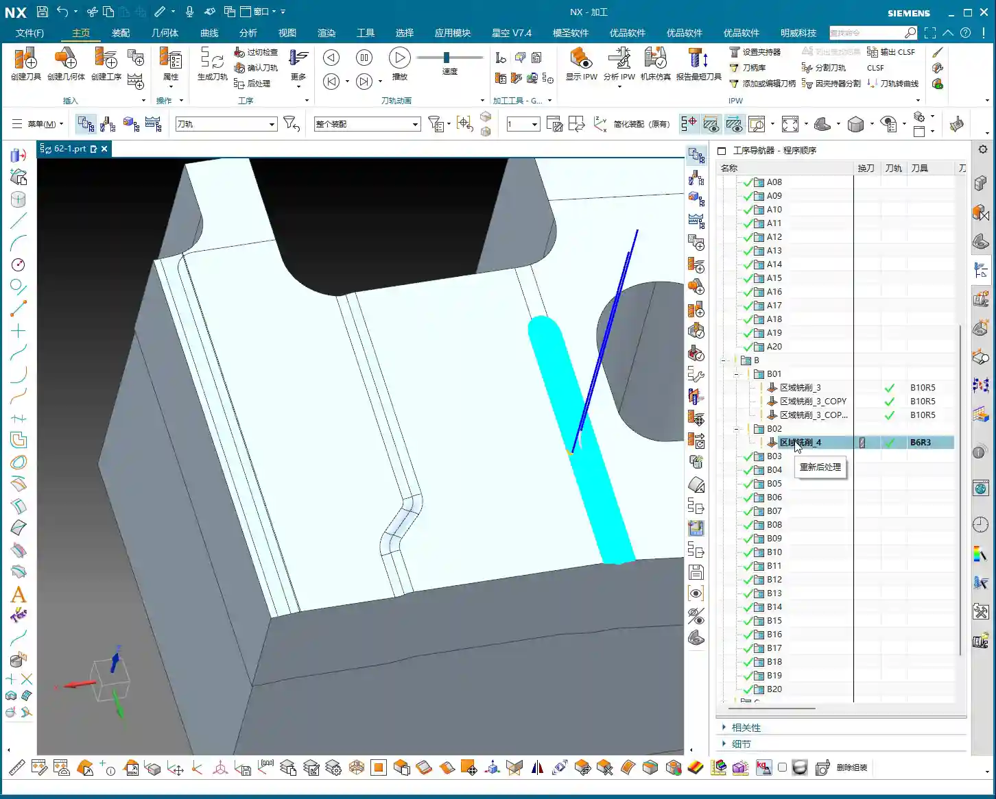
The Necessity of Secondary Roughing (Corner Cleanup)
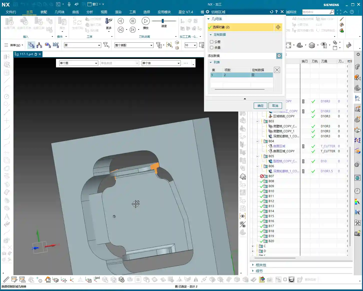
After roughing, don’t assume everything’s done. When roughing with a large cutter, material will inevitably be left in small corners and fillets. At this point, you need to perform a “secondary roughing” operation, which is essentially Corner Cleanup or Rest Milling. Select a tool one size smaller than your roughing cutter, for instance, a D10 (10mm diameter) or even a D8 (8mm diameter) end mill, to clean out the remaining material in these corners. This is done to reduce the burden on the finishing pass tool, preventing it from taking too heavy a Depth of Cut (DOC), which can affect tool life, cause chipping, or lead to workpiece surface quality issues. All corners that require machining must undergo Corner Cleanup to ensure smooth subsequent finishing passes. This step cannot be skipped; it’s the unsung hero that guarantees final part accuracy and surface quality.
Smoothing Operations and Maximum Distance Deviation
After secondary roughing, sometimes we use a “smoothing” function to achieve smoother tool paths and better surface finish. There’s a parameter here called Maximum Distance Deviation; don’t always stick to the default value. This value controls tool path accuracy, but if you want the tool path to be smoother, especially in less critical or transition areas, you can increase it appropriately. For instance, set it to 400%. This results in a cleaner tool path, reduces calculation time, and in actual machining, the impact on the final surface quality might be minimal, or even better. Of course, you must check the machining results; don’t adjust it blindly. A smoother tool path reduces frequent acceleration and deceleration of the machine, which also benefits machine wear.
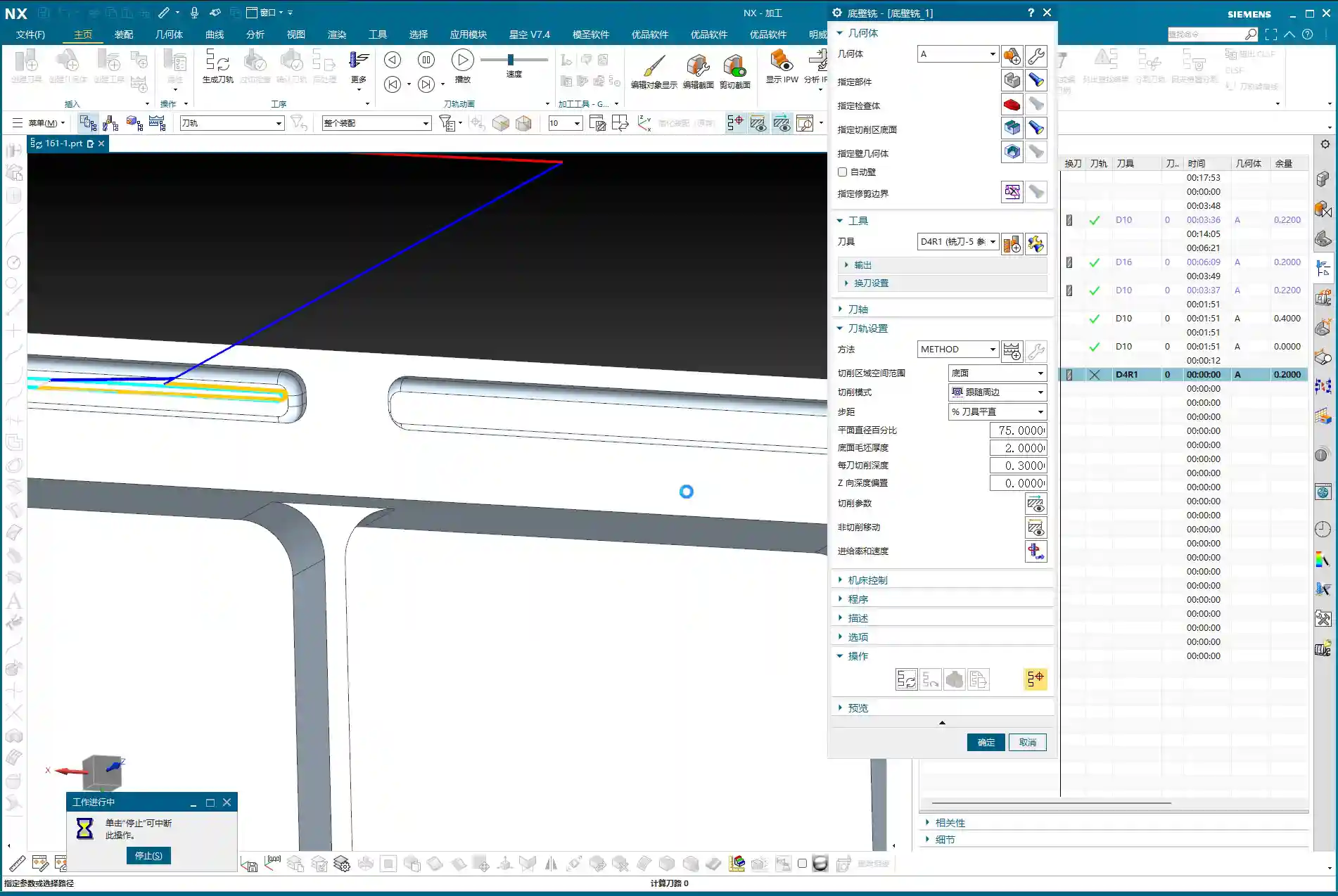

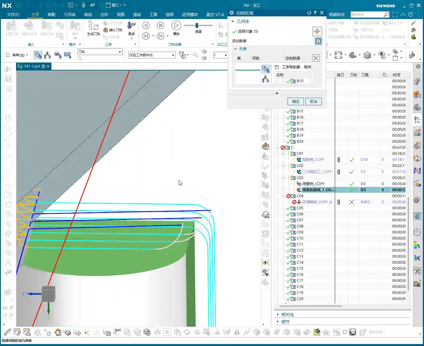
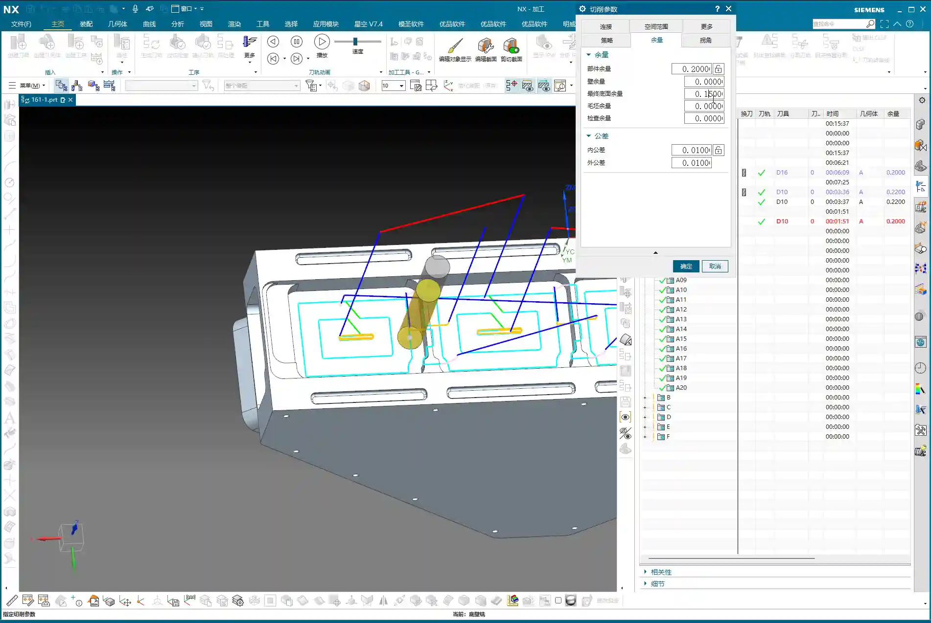
Bottom Surface Finishing Pass (Bottom Wall Milling)
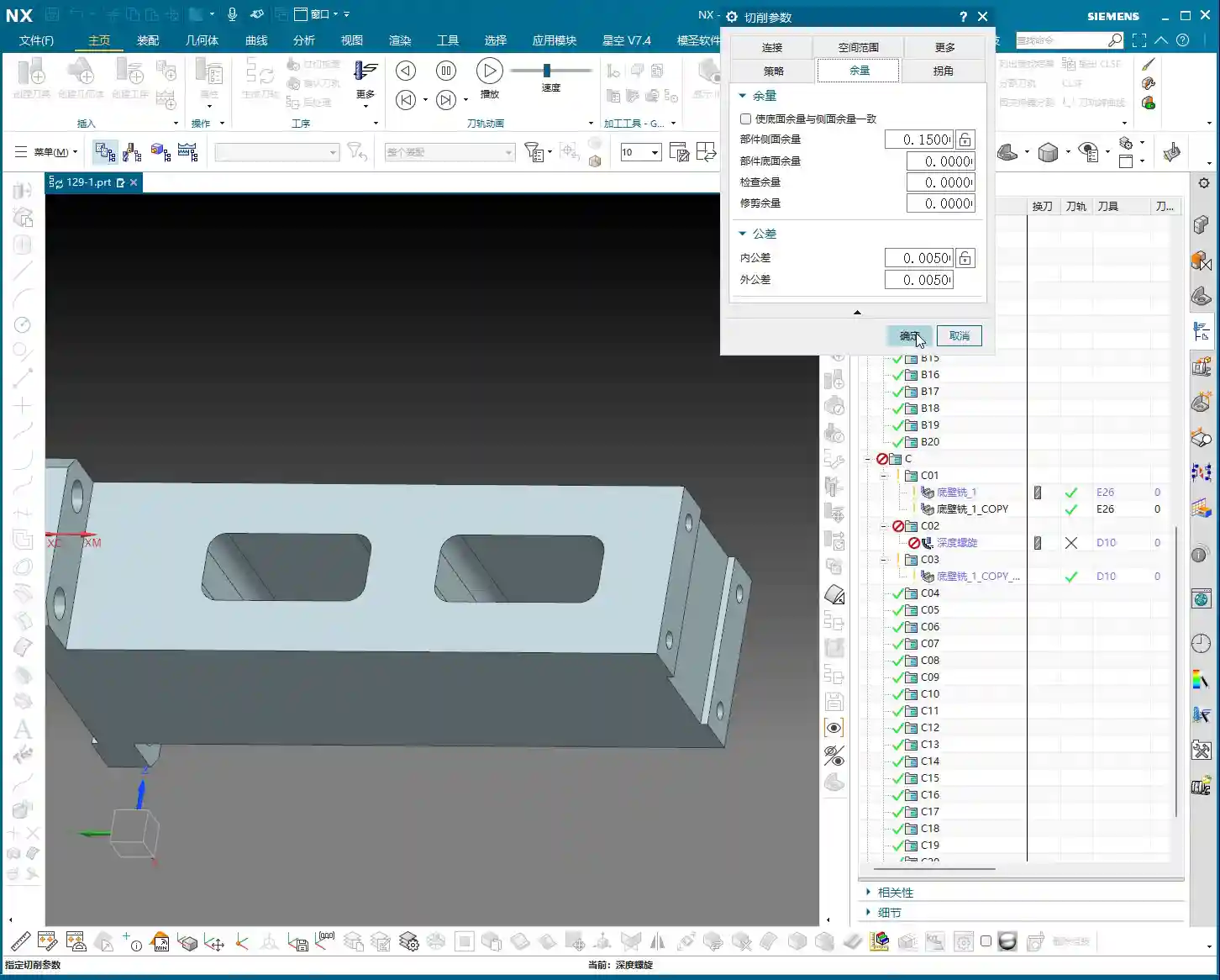
For the bottom surface finishing pass, we’ll use the “Bottom Wall Milling” operation. Select all bottom faces that require a finishing pass. Remember, for bottom surface finishing, you don’t need to adjust the tool axis direction; it defaults to being perpendicular to the bottom face, which perfectly suits our requirements. For tooling, you can continue using a D10 or D8 cutter to ensure accuracy and surface finish for the finishing pass. Crucially, the stock allowance for the bottom face must be set to 0. That’s what a finishing pass is all about – aiming for a mirror-like finish. Don’t underestimate a single bottom face; its flatness directly impacts the part’s assembly accuracy.
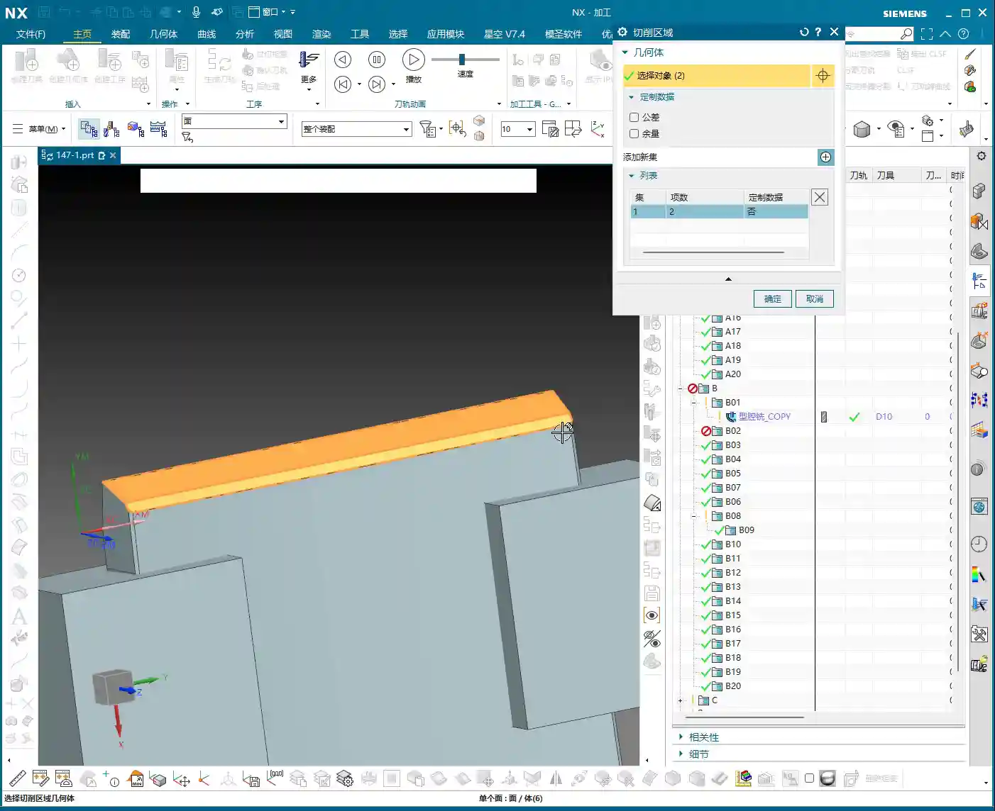
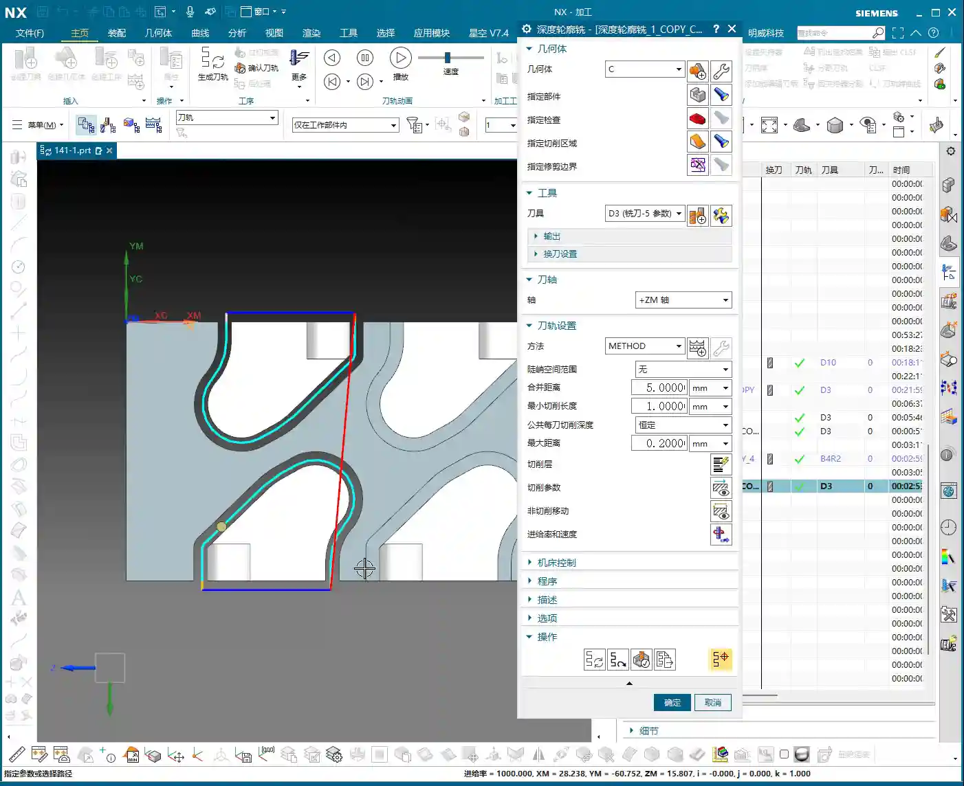
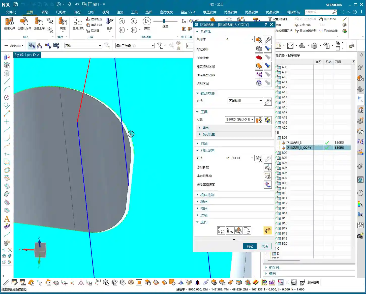
Side Wall Finishing Pass (Side Wall Milling)
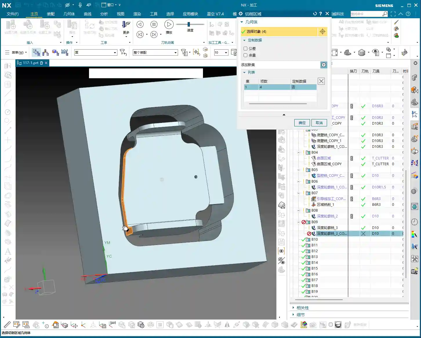
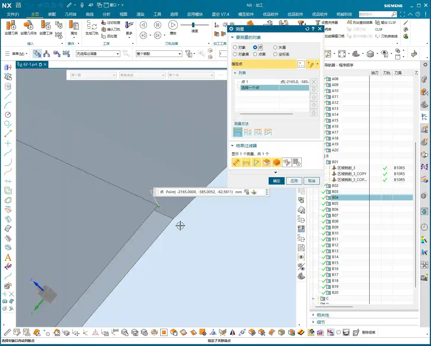
For the side wall finishing pass, similarly select the “Side Wall Milling” operation. Choose all side faces that require a finishing pass. At this point, the tool axis direction must be set to “upwards,” meaning along the normal vector of the side wall. When finishing side walls, there’s a crucial principle: if conditions allow and the tool length is sufficient, aim for a single-pass finish. This means the Depth of Cut (DOC) for each pass should be set to 0, allowing the tool to complete the cut from top to bottom in one go. This avoids tool marks and blend lines caused by layered cutting, ensuring the side wall’s surface finish and perpendicularity. The side wall stock allowance should also be set to 0. For corners, to ensure final accuracy, you might consider leaving a tiny allowance, such as 0.005mm, to be addressed in the final operation with a more precise tool or polishing. However, typically, for finishing passes, you’d set it directly to 0. This kind of single-pass, clean cut delivers both high efficiency and quality.
Summary: Pitfall Avoidance Guide
What I’ve covered today are hard-won lessons from my 15 years in the trenches, Master Wang’s blood, sweat, and tears. Listen up, there are a few critical points you absolutely must remember:
- Tool Axis Setting: For angle heads or 4-axis horizontal machining, the core is flexible tool axis transformation. If you can specify by selecting a face, do it – don’t shy away from the extra step.
- Rapid Move (G00) Trap: If a rapid move can be output using Linear interpolation (G01), absolutely do NOT use Rapid move (G00)! Unless you have 100% confidence in your machine and post-processor. Better to be a bit slower than unsafe.
- Retraction Optimization: Retraction paths should be short and flexible; use an arc if possible. Time is money, don’t waste it on air moves.
- Secondary Roughing / Corner Cleanup: This operation cannot be skipped; it’s a guarantee for your finishing pass. Clean up the remaining material, and the finishing pass will be much easier.
- Smoothing Strategy: Judiciously adjust the Maximum Distance Deviation to achieve smoother tool paths and improve efficiency.
- Finishing Pass Stock Allowance: For the bottom and side wall finishing passes, the final stock allowance should be set to 0 – this is a requirement for accuracy. For side walls, if conditions allow, aim for a single-pass finish.
Don’t just get carried away by fancy software simulations; whether the final part is acceptable ultimately depends on the sparks flying from the machine and the feel of the finished surface. Think one step further, observe one step more, avoid detours, and save money – that’s what true skill is all about!
👤 About the Author:
The author is a veteran CNC machining professional with 15 years of industry experience, specializing in UG NX programming. This article is an original work representing personal practical insights.
⚠️ Copyright Notice: Unauthorized reproduction or distribution without prior communication is strictly prohibited.