📝 Key Takeaways:
Practical Rib Machining (2nd Operation): Master Wang’s Guide to Siemens NX Programming & Optimization
First Step: Workpiece Coordinate System (WCS) B-Side Adjustment and Datum Definition
Hello everyone, this is Master Wang. In the last lesson, we discussed machining the front side of the connecting ribs. Today, we’ll continue and tackle the back side of this part, which is the second operation (Op 2). Listen up, this area isn’t simpler than the front; there are plenty of crucial details.
For the back side machining, the first step is to modify the Work Coordinate System. Simply change the primary Machine Coordinate System (MCS). To put it simply, select the B-side. Double-click the WCS and adjust the Z-axis direction to ensure it points towards the back side we intend to machine. Sometimes, when I’m too quick, I might place the origin in the middle, but that’s a no-go. This job demands high precision, so the origin must be placed at the designated location, like our datum corner, not just anywhere. One slip-up, and the tool will cut into the part.
Remember, whether it’s the A-side or B-side, as long as the Z-axis direction is correct, the program won’t show errors (turn red); this is fundamental Siemens NX logic. But don’t even think about double-clicking and directly modifying an A-side program to run on the B-side; that program will definitely error out and turn red! That operation is absolutely incorrect. As long as we ensure the J-axis points upwards, milling can commence from either side.
We also need to thoroughly check the datum points for the B-side, ensuring they correspond with the A-side datum points, both being at the same location. If the front’s datum is zero, then conversely, the back’s datum should also be zero. These finer points aren’t necessarily taught in textbooks.
Roughing Strategy: Rib Side Roughing and Stock Allowance
Rib Side Roughing Toolpath Optimization
Next is the **roughing** of the rib’s side. We need to **rough** out this area. Here’s a critical consideration: Is it better to **rough** everything out, or to **rough** to a certain face first, and then perform a **finishing pass**?
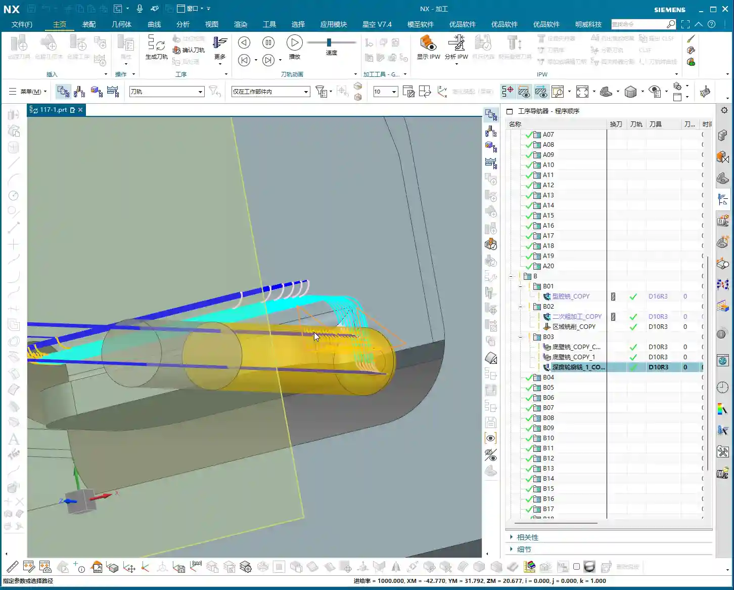
In my experience, for connecting ribs like these, especially if they are connected on both sides, we can start by only **roughing** down to this specific face. Once this area is **roughed** out, meaning the initial **Rest Milling** is complete, we then proceed with a Finishing pass. After the **finishing pass**, we perform another **roughing** operation, either a secondary **roughing** or semi-**finishing** mill. This staged approach can effectively reduce machining stress, which is paramount for preventing deformation, especially with materials like titanium alloys and high-temperature nickel-based alloys.
Therefore, we’ll first **rough** this face. Select the final face to ensure our **roughing** range is correct. Then, change the program mode from automatic to manual face selection. This allows for precise control of the machining area, preventing air cutting or milling into unintended regions.

Program Duplication and Parameter Adjustment Pitfalls
The programming method for the other side (front) is essentially the same as for this (back) side, so we can directly duplicate the previous roughing program. After duplicating, remember to change the WCS to the B-side, and then use Teach Geometry to control the toolpath. This will save a significant amount of time.
Oh, right, I think I selected the wrong tool earlier when programming the other side. You might have noticed. My apologies, I was a bit too quick! Let’s re-select; we should be using an R10 or R12.5 tool (the audio mentioned 12R3, then 10, then 12; I understand this as various options, ultimately choosing the most suitable). That’s how it is when you’re working—if you make a mistake, you fix it; don’t just power through it!
Once we finish programming, we *must* check everything: ensure all programs are set for either the A-side or B-side, and that the tools are correct. If everything checks out, then click generate. I sometimes get too quick and make selection errors. Such minor mistakes are common in production, but a single oversight can scrap a part worth hundreds of thousands (of RMB), so even the most seasoned machinist needs to be meticulous.
Duplicate all these **roughing** programs, then sequentially modify the WCS to the B-side and select the corresponding machining faces. Remember to adjust the spindle speed and feed rate (F-value and S-value) according to the material and tool conditions. For example, here, I’m setting the spindle speed to 1000 RPM and the feed rate to 100 mm/min (approx. 3.9 inches/min), but these are for reference only. Actual values must be determined based on the tool manufacturer’s parameters and machine performance. Don’t just rely on software simulations; observe the cutting sparks, listen to the cutting sound, and feel the chip temperature!

Detailing: Finishing Pass for Deep Pockets and Connecting Features
Corner Radius Area Treatment: The Clever Use of Offset Surfaces
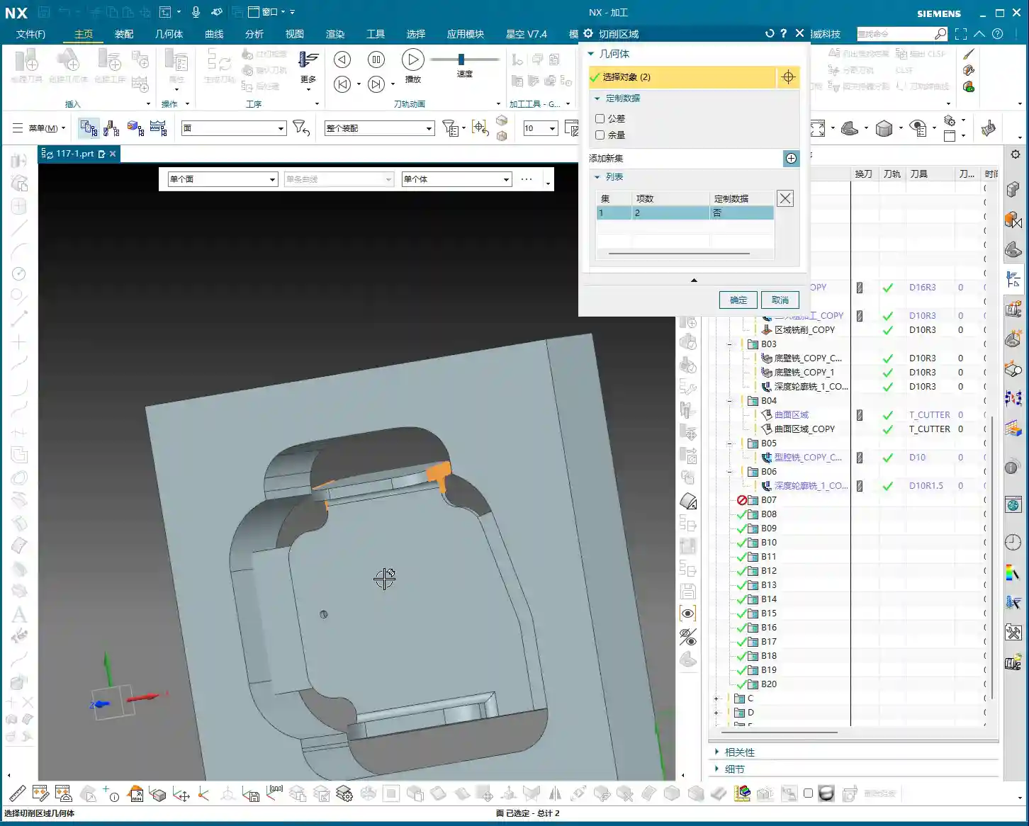
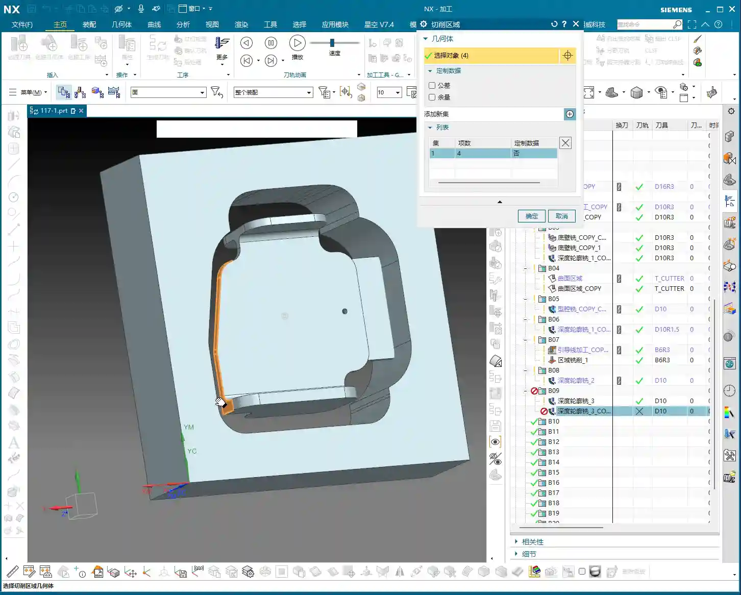
Now, let’s look at the corner radius areas of the connecting ribs. This spot is a bit complex, with many fillets. We generally avoid machining directly on these fillet regions. My approach is to first create an Offset Surface here. Essentially, we’re making a sheet body.
Why not just delete the fillet faces directly? Because direct deletion might lead to inaccurate recognition of other machining faces later on, or result in broken surfaces. Creating an **Offset Surface**, however, provides a smoother, more controllable guide surface for the toolpath without altering the original model. This is especially crucial in Contour Milling. Textbooks don’t teach you these workarounds, but on the job, you have to be flexible!
We simply select all machining faces, then create the sheet body; this makes it much easier to handle. This method is very convenient, ensuring toolpath quality and preventing overcut or undercut, especially when machining high-precision parts (±0.005mm, approx. ±0.0002 inches) – this detail can be a lifesaver!

T-Slot Cutter Selection and Fine-Tuning Parameters
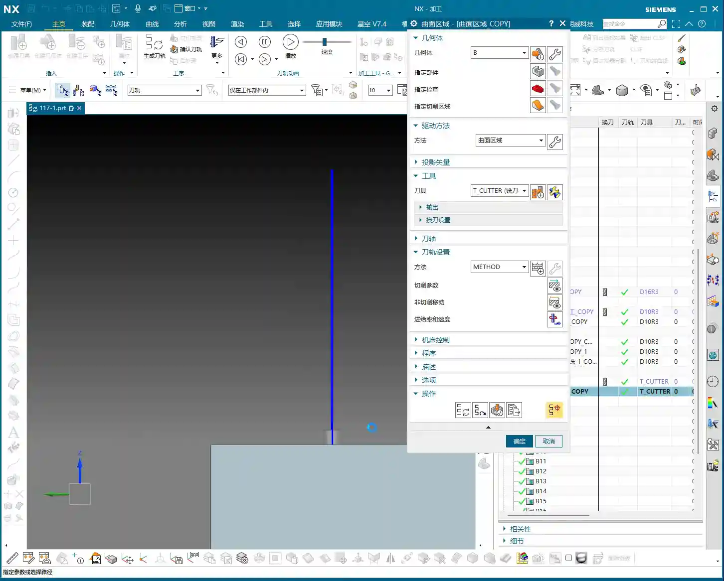
For some deep pockets or special connecting features, we might need to use a T-slot cutter, also commonly known as a ‘side-and-face cutter’ or a flat-bottom end mill with a corner radius, similar to tools used for milling slots.
When selecting tools, you can’t just rely on what’s available in the tool library. We must determine it based on the actual part dimensions, machining allowance, and machine rigidity. For instance, here, the audio mentioned R2, R4, R6, R10, R16 – these are common corner radii. However, we must also consider the Neck Diameter; if it’s too large, it could cause interference. For example, I might start with a 16mm diameter flat-bottom end mill with a 10mm neck, or even smaller, like a 6mm one. For specific corner radii, such as R2, you’ll need to use an R2 ball nose end mill or bull nose end mill for **Corner Cleanup**.
Don’t think tool selection is a minor matter. A good tool works faster, produces fewer scrapped parts, lasts longer, and naturally reduces costs.

Toolpath Control and Safety Verification
Lead-in/Lead-out and Non-Cutting Moves Strategy
Once the toolpath is programmed, don’t forget the settings for lead-in/lead-out and Non-Cutting Moves. These determine your machining efficiency and safety.
We can’t let the tool retract that high; retracting that high just wastes time and serves no purpose. We need it to retract slightly lower, but still ensure it doesn’t collide with the workpiece or fixturing. In Siemens NX, adjust the Clearance height to make it move closer to the workpiece surface, which boosts efficiency. For example, set the safe height to 2mm (approx. 0.08 inches) relative to the plane, rather than retracting to a very high position. Use Linear interpolation for Non-Cutting Moves and set the safety percentage to 60%; this approach is both safe and efficient.
Finally, don’t forget to finish the bottom surface. This requires another finishing pass program. Select the B-side and finish the bottom surface to ensure the desired surface finish. Naturally, if there are areas on the other side requiring special machining, we must handle them similarly.
Preventing Overcut: Toolpath Extension and Stock Control
Let’s check the toolpath, especially the final pass. If it overcuts, then the part is scrap. Don’t underestimate a 0.01mm (approx. 0.0004 inches) overcut; that’s still a scrapped part!
If the toolpath isn’t fully extended to the boundary, or there’s a risk of undercut, we can use surface percentage extension to make the tool travel slightly further, ensuring the edges are thoroughly cleaned. For example, extend outwards by 1mm (approx. 0.04 inches) or by a percentage of 5%. Simultaneously, ensure sufficient bottom stock allowance, such as 0.25mm (approx. 0.01 inches), to guarantee enough material for the **finishing pass**.
Our cutting direction is also crucial. From top to bottom, reverse the arrow’s direction to ensure appropriate cutting forces.
Finally, check if the first cut extends slightly upwards. Typically, we don’t need it to extend upwards unless there’s a specific **Corner Cleanup** requirement. If it’s just **roughing**, reaching the bottom is sufficient. Starting milling from this position, after **roughing**, this area should be fine. Ensure the toolpath just reaches this edge; this also makes the first cut reasonable.
The top surface also needs extension, because the final pass might overcut, which isn’t ideal. Let’s set the top surface extension percentage to 99.99%, or extend it slightly, which ensures both **Corner Cleanup** and prevents overcut.
Summary: Pitfall Avoidance Guide
- Coordinate Systems (WCS/MCS) are Fundamental: No matter what, always ensure the WCS is set correctly, the Z-axis direction is accurate, and the origin is precise. Selecting the wrong coordinate system will render all subsequent efforts useless.
- Tool Selection and Parameter Matching: Never choose tools arbitrarily. Select the appropriate tool type, diameter, corner radius (R-value), and neck diameter based on workpiece geometry, material properties, and machining requirements. Cutting parameters (spindle speed, feed rate) must be combined with practical experience and manufacturer data.
- Toolpath Simulation and Actual Machining Integration: Siemens NX simulation, no matter how realistic, is still just a simulation. During actual cutting, observe the sparks, listen to the sound, and smell the chips to make timely adjustments.
- Handling Complex Geometries: When dealing with complex features like fillets and deep pockets, flexibly use advanced Siemens NX functions like **Offset Surfaces** (sheet bodies) to avoid direct programming on complex faces, thereby reducing machining risks.
- Balancing Efficiency and Precision: Optimize lead-in/lead-out and clearance heights to reduce air cutting time and improve machining efficiency. However, this must be predicated on ensuring machining precision and safety; 0.005mm (approx. 0.0002 inches) accuracy is absolutely non-negotiable.
- Preventing Heat Treatment Deformation: For materials prone to deformation, **roughing** and **finishing passes** should be staged. Control the stock allowance and cutting parameters for each step to minimize internal stress.
- Fixturing Design: Secure clamping is a prerequisite for high-precision machining. For parts like connecting ribs, stability of fixturing is especially critical for the 2nd operation to prevent deformation during re-clamping.
- Frequent Checks, No Laziness: After every parameter modification or program duplication, always re-check everything, especially the tool, machining faces, and toolpath direction. A small mistake can lead to significant losses.
👤 About the Author:
The author is a veteran CNC machining professional with 15 years of industry experience, specializing in UG NX programming. This article is an original work representing personal practical insights.
⚠️ Copyright Notice: Unauthorized reproduction or distribution without prior communication is strictly prohibited.
Leave a Reply