Tag: Cutting Parameters

  • Siemens NX Cavity Milling Cutting Parameters Explained: Master Wang Guides You Through Complex Rough

    📝 Key Takeaways: ** Master Wang provides a hands-on guide to Siemens NX cavity **roughing** strategies. Drawing from 15 years of practical experience, Master Wang meticulously explains the intricacies and pitfalls of each parameter, from cutting order and toolpath direction to stock settings and non-cutting moves. This helps you optimize toolpaths, enhance machining efficiency and precision, moving beyond textbook theory to address real-world production challenges. **

    Hello everyone, I’m Master Wang. Today, we’ll continue discussing Siemens NX cavity milling operations. Last time, we covered some fundamental program creation. Today, we’re diving deep into the internals of cutting parameters to share practical tips you won’t find in textbooks. Listen closely, because a slight oversight in these areas can lead to **tool deflection** or significantly reduced efficiency.

    Key Parameters for Cavity Roughing Strategy in Siemens NX

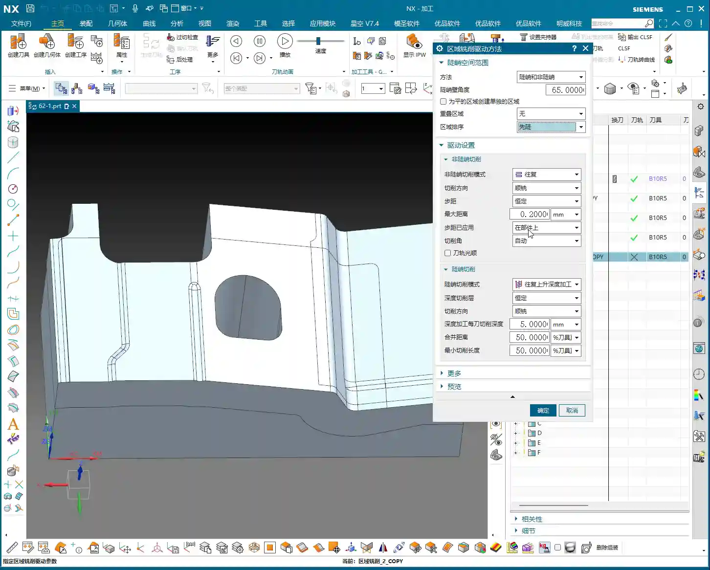
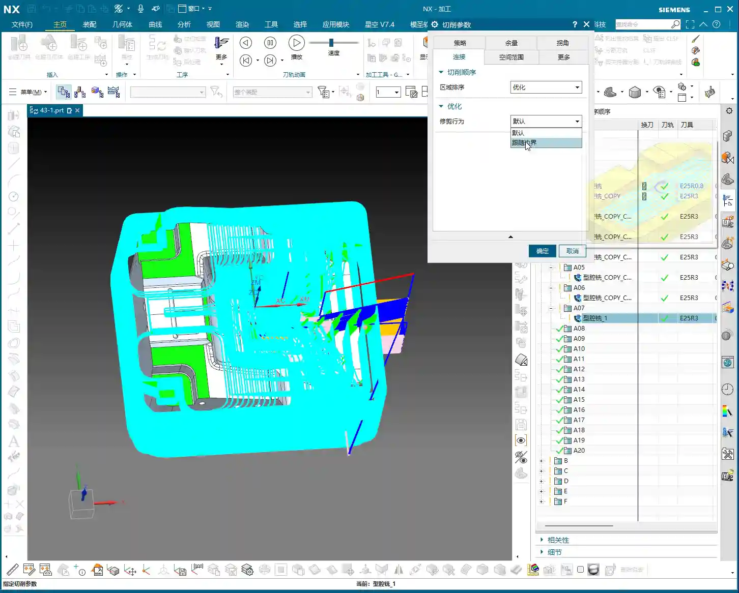
    Cutting Order: The Wisdom of Depth First

    As we’ve discussed before, Siemens NX provides options for Depth First and Level First. I always say that for cavity **roughing**, in most cases, we’ll opt for Depth First. Why?

    • Improved Chip Evacuation: Depth First allows the tool to cut to a specified depth within one area first. This creates more space for chips to evacuate, preventing clogging and reducing re-cutting, naturally extending tool life.
    • High Cutting Stability: With each **stepdown**, the cutting load remains relatively stable. Unlike Level First, which sweeps through the entire area layer by layer, switching back and forth, Depth First helps avoid vibrations that can affect machining accuracy and surface quality.

    Of course, this isn’t an absolute rule; special situations require special handling. However, defaulting to Depth First is usually the right choice.

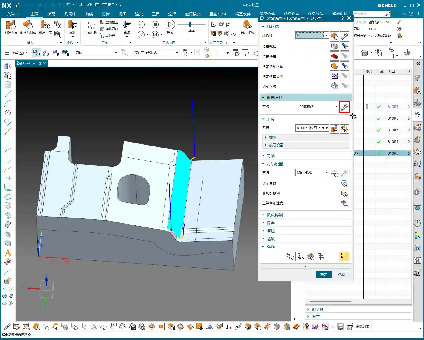
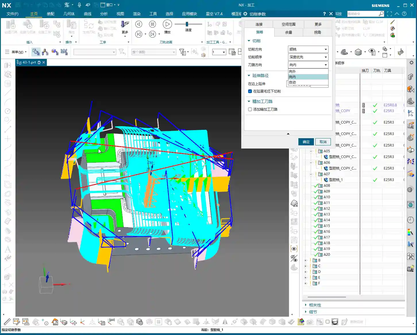
    Toolpath Direction: The Secret of Smart “Automatic”

    Toolpath direction used to only offer a few options: Inward and Outward. Inward means milling from the outside in, and Outward means milling from the inside out. For enclosed cavities, Inward might be better; for open cavities, Outward might be smoother. But did you know that Siemens NX now has a particularly useful option called Automatic!

    • Automatic Detection, Doubled Efficiency: This “Automatic” function isn’t just a random choice. The software intelligently determines whether the current area should be cut “Inward” or “Outward” based on your part’s geometric features, such as whether it’s an enclosed cavity or has open boundaries. This significantly reduces idle cuts. For instance, in open areas, it will directly enter the material from the outside, avoiding plunging inside solid material before moving outward.
    • Reduced Manual Intervention: Especially for complex parts with a mix of enclosed and open areas, manually distinguishing and setting these parameters would be time-consuming and prone to errors. Entrusting it to “Automatic” saves effort, reduces hassle, and results in more optimized toolpaths.

    Therefore, under normal circumstances, simply use “Automatic” here. Don’t underestimate this small option; it can save you a lot of valuable machine time.

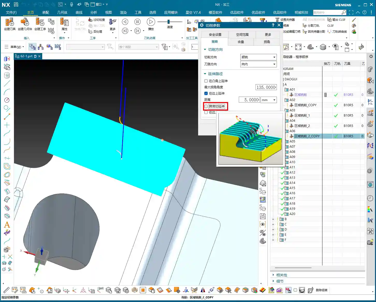
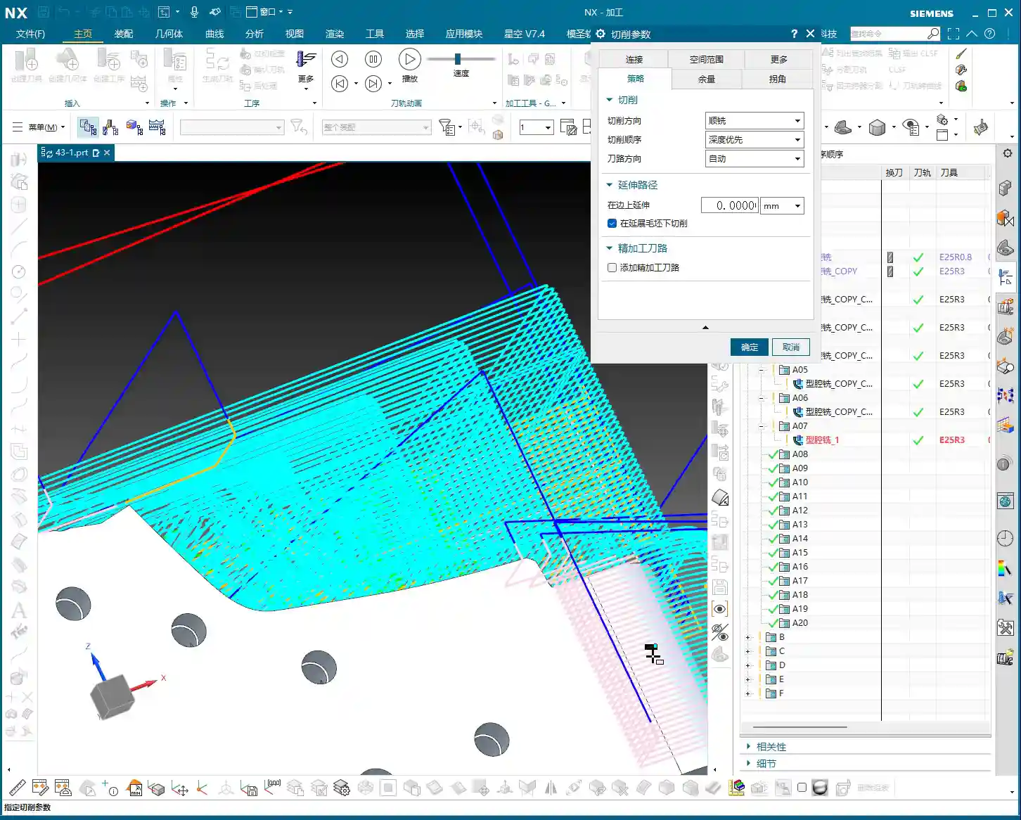
    Cut Along Blank Underneath: The Choice for Multi-Sided Machining

    This parameter, called Cut along Blank Underneath, determines whether the tool should continue cutting into the blank material below the currently defined cutting layers. Let me give you an example, and you’ll understand immediately.

    Imagine a part where you first machine Face A, then flip it over to machine Face B. Face A has already been **roughed** to a certain depth, but this depth might have cut past the part’s centerline, or even slightly into a portion of the blank material that will be machined for Face B. Now you’ve flipped it over and begun machining Face B.

    • If checked (default is checked): Even if the defined machining range for Face B is sufficient up to a certain depth, if there’s still blank material below that depth, the tool will continue to cut downwards until all blank material is removed. This could lead to re-cutting areas already machined on Face A, or cutting into unintended areas. For multi-sided machining with part flips, this might result in over-cutting or idle moves.
    • If unchecked: The tool will strictly adhere to the part boundaries defined for the current operation. It will only cut the blank material that is above or on the part’s surface for the current operation. Even if there’s a significant amount of material below the part surface, it won’t be touched. This is extremely useful in multi-sided machining or when pre-machining has occurred, ensuring the tool only removes the necessary stock for the current face, avoiding unnecessary deeper cuts, saving time, and enhancing safety.

    So, when performing multi-sided machining or operations with pre-machined features, you must carefully consider this option. The default checked state may not be suitable for all situations; sometimes, unchecking it can lead to smarter and safer toolpaths.

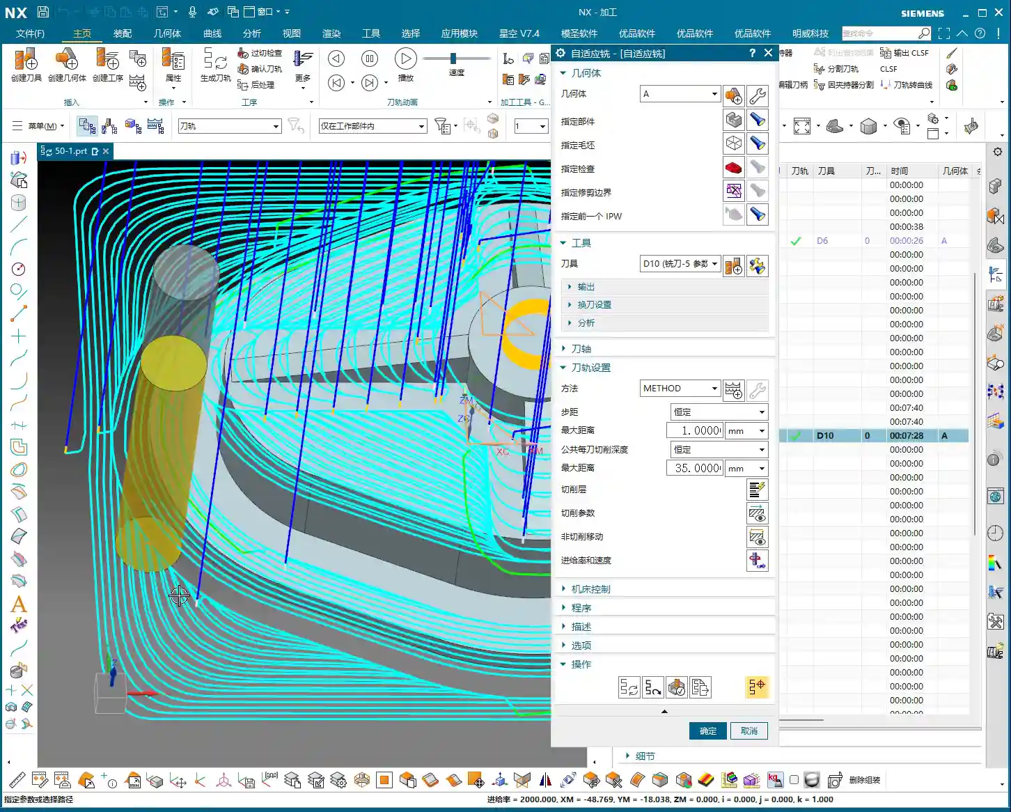
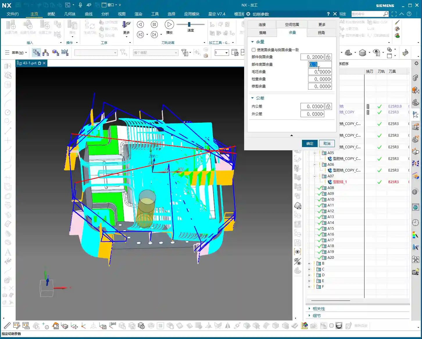
    Stock Settings: Crucial for Roughing and Finishing

    Stock is material left for **finishing passes**. During **roughing**, Side Stock and Bottom Stock are usually set to a positive value. For example, during **roughing**, we typically leave about 0.3 mm (approx. 0.012 inch). This value isn’t arbitrary; it must be determined by considering your machine’s precision, tool rigidity, material hardness, and the allowance for the **finishing pass**.

    • Roughing Stock: If too little stock is left, the **finishing pass** tool will experience excessive load, leading to wear or even chipping. If too much stock is left, the **finishing pass** will involve too many cuts, wasting time. Therefore, finding this balance point, relies on experience and practical considerations.
    • Finishing Stock: The stock for **finishing passes** is much smaller, typically 0.15 mm (approx. 0.006 inch) or even less, to ensure final dimensions and surface finish.

    Individual Stock Control: Flexible or Unified?

    Siemens NX features a small checkbox here. If you enable it, Side Stock and Bottom Stock will be linked. This means if you change one, the other will update automatically. For example, if you want both to be 0.2 mm (approx. 0.008 inch), just check the box and modify one. If you want 0.2 mm for the side and 0.3 mm for the bottom, then uncheck the box and set them separately.

    My recommendation is, unless your stock requirements for side walls and bottom surfaces are absolutely identical, it’s best to set them separately. This provides greater flexibility and better adapts to the machining needs of different parts. For instance, the **finishing pass** at the bottom of some deep cavities might be challenging, potentially requiring more stock.

    Blank Stock: The Art of Precise Positioning

    The Blank Stock parameter essentially offsets the blank model we initially created outwards by a certain distance. For example, if you set it to 10 mm (approx. 0.39 inch), your existing blank model is expanded by 10 mm.

    As Master Wang, I generally don’t use this function much. Why? Because we typically directly create a precise solid blank model or use offset geometry to define the blank. This is more intuitive, accurate, and better reflects the actual blank dimensions. Directly applying an offset value here can sometimes lead to confusion with the actual blank size, and accuracy can be compromised, especially with complex blank shapes. Unless absolutely necessary, don’t use this feature carelessly.

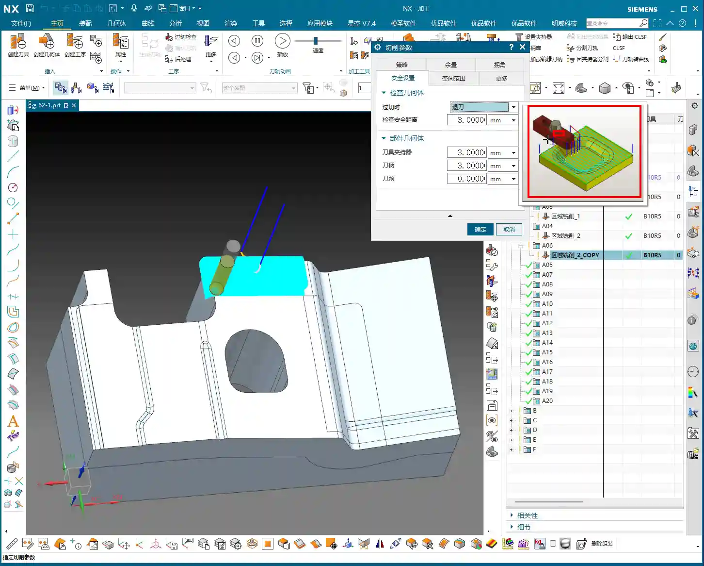
    Check Stock and Trim Stock: Ensuring Safety and Efficiency

    • Check Stock: This parameter is used to prevent collisions between the tool and **fixturing** components like clamps or pressure plates. You can model your **fixturing** in Siemens NX and then set a check stock for it, for example, 0.5 mm (approx. 0.02 inch). This way, the tool will automatically avoid the fixture, leaving a 0.5 mm gap, ensuring machining safety. This is a critical safety parameter, and you must be mindful of it, especially in complex **fixturing** setups or close-tolerance machining.
    • Trim Stock: When you use trim boundaries to limit the toolpath range, this parameter defines the stock left relative to the trim boundary. It can be set to be Inward or Outward. For instance, if you’ve drawn a boundary and want the toolpath to retract slightly inward from that boundary, you can set a positive value. This is very useful for local **corner cleanup** or avoiding specific areas.

    Inner/Outer Tolerance and Corner Handling: Details Determine Quality

    • Inner/Outer Tolerance: These two control toolpath accuracy. During **roughing**, a larger tolerance can be applied, such as 0.1 to 0.3 mm (approx. 0.004 to 0.012 inch), as the primary goal of **roughing** is rapid material removal. However, for **finishing passes**, the tolerance must be very small, typically 0.01 mm (approx. 0.0004 inch) or even less, to ensure the final part dimensions and surface finish meet requirements.
    • Corners: This parameter controls whether a transition radius is applied to the toolpath when entering or exiting corners. During **roughing**, we typically apply a small transition radius, such as 0.2 mm or 0.5 mm (approx. 0.008 or 0.02 inch). This offers several benefits:

      • Tool Protection: Prevents the tool from sudden changes in direction at sharp corners, reducing impact, tool wear, and chipping.
      • Smooth Cutting: Results in smoother toolpaths and more stable machine operation, reducing vibrations and helping maintain machining accuracy.

      The specific size depends on the tool diameter, material hardness, and how much sharp corner material you aim to remove during the **roughing** stage.

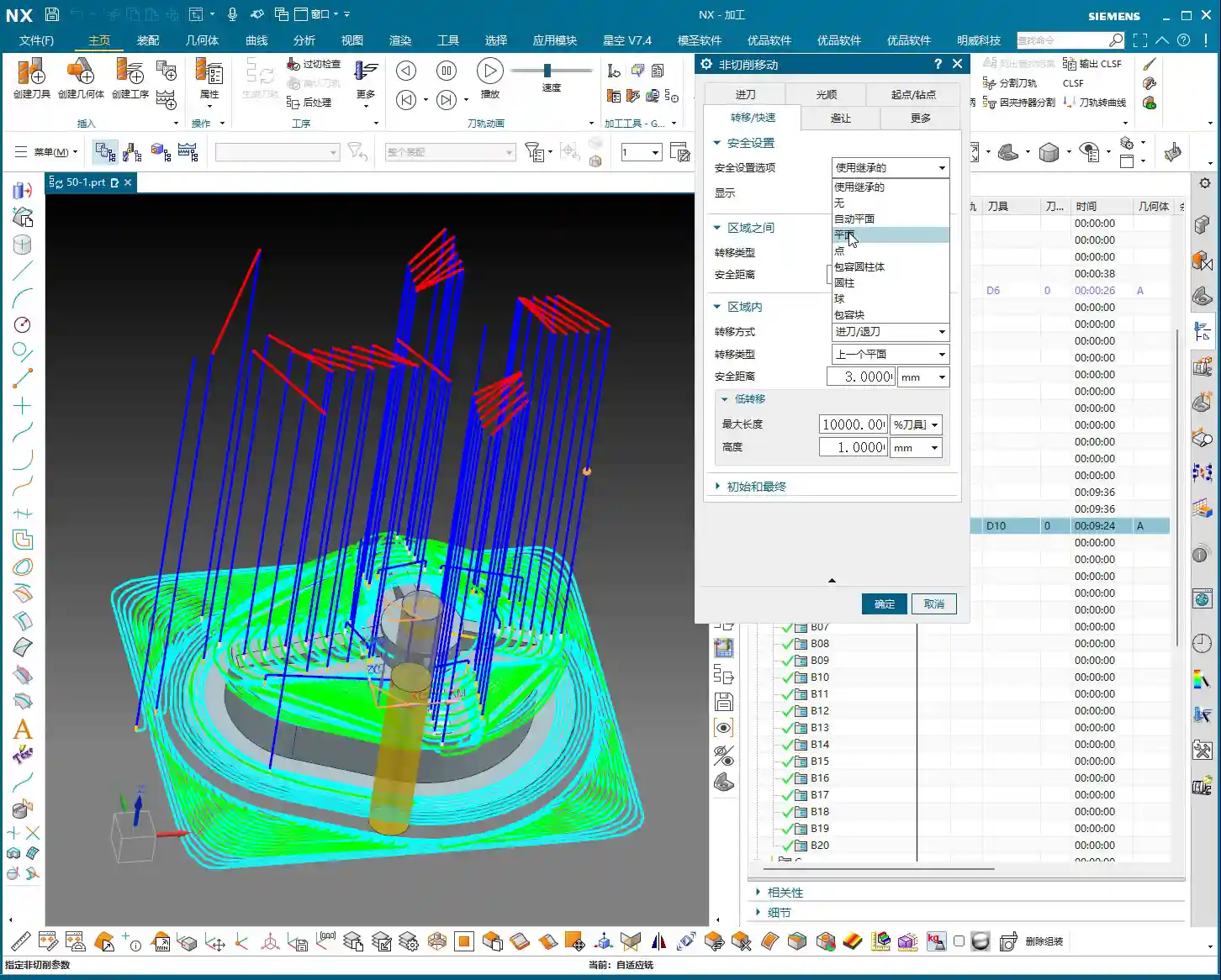
    “Cutting Flatness” in Non-Cutting Moves: Guardian of Tool Life and Machining Quality

    This parameter, found under Non-Cutting Moves, is called Cutting Flatness. Don’t underestimate it; it significantly impacts tool life and machining quality, especially when using indexable insert tools or certain end mills without a center cutting edge.

    Its purpose is to prevent the non-cutting parts of the tool (such as the tool center or the non-cutting body of an indexable insert) from scraping the bottom of the workpiece when encountering flat bottom regions, which could degrade surface quality or cause tool wear. It is typically defined as a percentage of the tool diameter.

    • Practical Significance: If you set an excessively large value, for example, 10 mm (approx. 0.39 inch) (relative to a tool with a small diameter), and the tool’s effective cutting length or insert height is much smaller than this value, then in flat areas, the tool body will **”gouge”** or directly impact the workpiece, leading to tool damage or scrapped parts.
    • Recommended Setting: We typically assign a percentage, such as 45% to 65%. This means that when the **depth of cut** or the dimension of a flat region encountered is less than this percentage, the tool will adopt strategies like lifting, arc transitions, etc., to prevent non-cutting portions from contacting the workpiece. This both protects the tool and ensures the flatness and finish of the bottom surface.

    This parameter is especially crucial for expensive indexable insert tools; you must understand it thoroughly and never change it haphazardly!

    Summary: Pitfall Avoidance Guide

    In our line of work, simply relying on textbook theory isn’t enough; you must combine it with practical experience. The parameters discussed above are insights I’ve gathered from 15 years of hands-on experience in the field – every word is valuable. Finally, here are a few reminders, born from hard-learned lessons:

    • Don’t Arbitrarily Choose Cutting Order: Unless you have specific requirements, “Depth First” is the primary choice for cavity roughing. Blindly using “Level First” can easily lead to poor chip evacuation, rapid tool wear, and even chip packing or tool breakage.
    • Trust “Automatic” for Toolpath Direction: For complex cavities, manually selecting “Inward/Outward” can result in numerous idle cuts and low efficiency. Modern software is intelligent; make frequent use of “Automatic”. It will help you find the most logical path, saving you significant time in judgment and adjustment.
    • Thoroughly Understand “Cut Along Blank Underneath”: Especially in multi-sided machining or when pre-machining has occurred, misunderstanding this option can lead to re-cutting already machined surfaces, or plunging the tool in unintended areas. At best, this wastes time; at worst, it causes tool crashes and scrapped parts. Before each multi-sided machining operation, always check or uncheck this option based on the actual situation and simulate carefully.
    • Stock Settings Require Balance: If **roughing** stock is too small, the **finishing pass** tool won’t have a consistent cut, leading to **tool deflection** or chipping. If too large, it increases the **finishing pass** burden and wastes time. You must find the optimal sweet spot based on material, tool, and machine conditions.
    • Blank Stock, Use with Caution: Unless the blank shape is extremely simple, do not solely rely on this parameter to define complex blanks. It’s best to use solid blank models or offset curves to minimize errors.
    • “Cutting Flatness” is Key: For indexable insert tools or flat-bottom end mills, improper settings for this parameter can cause the tool center or non-cutting portions to scrape the bottom of the workpiece, affecting surface finish or even damaging the tool. Default values are often based on experience, but you should still understand the underlying principles based on the tool and workpiece characteristics.

    Remember, these parameters are static; the machinist is dynamic. Observe cutting sparks, listen to machine sounds, and think critically—experience will naturally follow. All right, that concludes today’s lesson. We’ll discuss something else next time.

    👤 About the Author:
    The author is a veteran CNC machining professional with 15 years of industry experience, specializing in UG NX programming. This article is an original work representing personal practical insights.

    ⚠️ Copyright Notice: Unauthorized reproduction or distribution without prior communication is strictly prohibited.

  • Master Wang Guides You Through NX Area Milling: Cutting Parameters, Boundary Extension, and Check Ge

    📝 Key Takeaways: Master Wang provides a hands-on guide to the core parameter settings for NX Area Milling. From cutting strategies for steep/non-steep regions, to boundary extension techniques for improved surface quality, and check geometry settings to prevent machine collisions – these are the distilled insights from 15 years of a veteran engineer’s practical experience. Mastering these will revolutionize your machining efficiency and part accuracy, allowing you to easily avoid machining pitfalls.

    Hello everyone, I’m Master Wang. Today, let’s continue our discussion on NX machining, especially focusing on critical points rarely detailed in textbooks, but which significantly impact efficiency and accuracy on the shop floor. Listen up, this is practical knowledge gained from my 15 years of hands-on experience and countless lessons learned the hard way!

    Area Milling Cutting Parameters: The Secrets of Steep vs. Non-Steep Regions

    When it comes to Area Milling, especially for complex surface machining, the cutting strategies for “steep areas” and “non-steep areas” in NX are crucial. Grasping these concepts will ensure your toolpaths are both fast and stable.

    What are Steep and Non-Steep Regions?

    Simply put, steep regions are areas with a significant incline, where a more vertical tool approach provides greater cutting stability. Conversely, non-steep regions are flatter areas, where horizontal toolpaths offer higher efficiency and better surface finish control.

    In NX, this distinction is based on an angle parameter. The system automatically determines which areas are steep and which are non-steep based on your set angle, and then applies the corresponding toolpath strategy. What’s this called? It’s like “teaching according to aptitude”—using the most suitable method to tackle different regions.

    Angle Setting and Practical Application

    In NX, the default angle for distinguishing steep/non-steep regions is typically 65 degrees. Most of the time, just use this default value; don’t change it arbitrarily. Why? It’s an empirically proven value, verified through extensive practical application, that suits most materials and workpiece conditions.

    • Above 65 degrees: Toolpaths typically employ the “steep” strategy, with tool motion oriented more vertically, suitable for machining deep cavities, side walls, etc.
    • Below 65 degrees: Toolpaths typically employ the “non-steep” strategy, with tool motion oriented more horizontally, suitable for machining flat or slightly inclined surfaces.

    Of course, in some special cases, for instance, if your workpiece sidewall has a slight angle but isn’t steep enough (e.g., a small incline like 5 degrees), theoretically, you could still use the steep region strategy. But let me be frank, don’t overcomplicate things in such situations. Changing too many parameters might not even give you the desired toolpath. For such small angles, if you want a better finish, using “Depth Contour Milling” to skim the surface might be better, even if it’s a bit more involved to set up. In most cases, simply using non-steep area milling (planar machining) works just fine, and it will cover the adjacent surfaces.

    So, in daily operations, when you encounter such areas, simply enable both “steep” and “non-steep” strategies simultaneously, letting the system automatically determine and switch, which is the most hassle-free and reliable approach.

    The Importance of Ordering

    When selecting both steep and non-steep area milling strategies, NX will also prompt you to choose a machining order. Should steep regions be machined first, or non-steep regions? Or from top-down, or bottom-up?

    In my experience, I generally opt to machine steep regions first. Why? Steep regions often involve deep cavities and side walls of the workpiece. By addressing them first, you leave a clear machining space for the subsequent non-steep (flat) areas. Of course, this isn’t an absolute rule; it depends on your workpiece geometry and machining requirements. But defaulting to steep regions first is a good choice.

    Toolpath Optimization Tool: Extend at Boundary

    “Extend at Boundary” might seem insignificant, but it’s critically important, especially when striving for high surface finish in a Finishing pass. It helps you thoroughly eliminate “tool marks” at the cutting boundaries.

    Why Extend?

    Have you ever encountered a situation where: the tool path looked perfect in the software simulation when cutting to the workpiece edge, but the actual machined edge always had a faint mark or some burrs? This is because the tool didn’t “fully exit the cut.”

    When you enable and set “Extend at Boundary,” the toolpath won’t stop exactly at the model’s edge; instead, it will extend a small distance beyond. This allows the tool to completely exit the workpiece, leaving the edge cleanly machined, preventing the tool from “compressing” or “dragging” material at the boundary. It’s like cutting paper with scissors – you always cut a little beyond the line to ensure a clean edge.

    What is the Appropriate Extension Amount?

    The extension distance is generally recommended to be set between 0.5 to 2 mm (approx. 0.02-0.08 inch). The specific value depends on your tool diameter and material. For small diameter tools, such as a Φ6 mm (approx. 0.236 inch) ball end mill, an extension of 0.5-1 mm (approx. 0.02-0.04 inch) is usually sufficient. For larger tools or stickier materials, 1-2 mm (approx. 0.04-0.08 inch) extension will be more reliable. When I adjust this parameter to 1 mm or 2 mm, you can clearly see the toolpath extend, and the surface quality immediately improves. Unlike the four-sided extension in “Depth Contour Milling”, this “Extend at Boundary” is primarily for managing tool entry and exit at workpiece boundaries, aiming for perfect edges. Remember, sometimes details determine success. Get these small things right, and your customer will be satisfied.

    Avoiding Obstacles, Efficient Machining: Check Geometry (Skip and Retract)

    This section is of paramount importance! In actual machining, the biggest fear is the tool colliding with fixtures, clamps, or protrusions on the workpiece. NX’s “Check Geometry” function, particularly the “Skip” and “Retract” options, directly impacts your machine and tool safety, as well as machining efficiency.

    What to do when a clamp appears? Retract vs. Skip

    Imagine your tool happily cutting, then suddenly a clamping plate blocks its path. How should the system handle this?

    • Retract: This is NX’s default setting and the safest strategy. When the tool encounters an obstacle, it will automatically lift, bypass the obstacle, and then re-engage to continue machining. The entire process is: Lift → Traverse → Re-engage. While safe, the drawback is increased retraction cycles, extending machining time, and potentially leaving slight marks where the tool lifts and re-engages, though often not prominent.
    • Skip: If you select “Skip,” the system assumes the obstacle poses no threat (e.g., it’s very low, or the tool can pass over it without issue). The tool will directly traverse over the obstacle without retracting. The entire process is: Traverse. This method is highly efficient, saving retraction and re-engagement time, and resulting in a smoother toolpath.

    Here’s the key point: NX’s “Skip” function typically has a “safety distance” or “skip clearance,” for example, a default of 3 mm (approx. 0.118 inch). This means if the obstacle’s height is within 3 mm above the tool’s current position, it will opt to skip. Beyond this range, it will default back to retract. Of course, this value can be adjusted.

    Master Wang’s Advice: The default “Retract” strategy is the safest. Especially for beginners, absolutely do not change it arbitrarily. Only consider using “Skip” to improve efficiency when you are 100% certain that the clamp or obstacle is low enough and the tool will absolutely not make contact. Don’t just rely on software simulations; no matter how good they look, a tool crash on the actual machine is no joke – it can range from scrapping the workpiece to damaging the machine. I often say, “Don’t just look at the software simulation; look at the cutting sparks,” and that’s exactly what I mean. Practical operational experience and thorough inspection are paramount.

    Risks and Benefits of Skipping

    Risks: If you misjudge the obstacle’s height, or if the fixture isn’t precisely modeled, the tool will collide when “skipping,” leading to tool breakage or even machine damage. Such losses far outweigh the small amount of machining time you might save.

    Benefits: In certain specific situations, such as using very short tools, or when obstacles (like a pre-machined boss on the workpiece) are genuinely low, or if you’re using a 5-axis machine that can cleverly avoid obstacles, then “Skip” can significantly boost machining efficiency and reduce air cutting time. Especially in high-volume production, these small efficiency gains accumulate into a substantial cost advantage. Therefore, understanding when to use “Skip” and when to use “Retract” is a crucial skill for any qualified NX programmer.

    Roll Tool on Boundary? Mostly Unnecessary

    Additionally, NX has an option called “Roll Tool on Boundary.” In essence, this function makes the tool “roll” an extra pass when it encounters an edge. But in my experience, this feature is largely useless. It just causes your tool to make an extra cut, increasing unnecessary machining time with minimal improvement to surface quality. Therefore, I recommend you keep it unchecked by default, unless you have a very specific requirement.

    Summary: Pitfall Avoidance Guide

    1. Steep/Non-Steep Region Division: Most of the time, the default 65-degree division angle is sufficient. It’s best to enable both strategies simultaneously, allowing the system to switch automatically.
    2. Toolpath Ordering: Prioritize machining steep regions first, then process flatter surfaces to maintain a smooth machining flow.
    3. Extend at Boundary: This is a powerful tool for improving surface finish. Always enable it and set a reasonable extension amount (0.5-2 mm). It effectively prevents edge marks and burrs.
    4. Check Geometry (Skip/Retract): The default “Retract” is the safest. Only consider using “Skip” to increase efficiency when you are 100% certain of safety (e.g., obstacles are very low and have been cleared). Otherwise, it’s better to go slower and ensure foolproof operation. Remember, safety first, efficiency second.
    5. Other Infrequently Used Functions: For instance, “Roll Tool on Boundary” should generally be left unchecked by default, unless there’s a special circumstance.

    Practice and review these parameters frequently. Especially after generating toolpaths, always simulate extensively and critically analyze. Behind every parameter lies a connection to the actual cutting process and potential issues. By constantly asking “why,” you can truly grow from a programmer into a skilled “Machining Master”!

    👤 About the Author:
    The author is a veteran CNC machining professional with 15 years of industry experience, specializing in UG NX programming. This article is an original work representing personal practical insights.

    ⚠️ Copyright Notice: Unauthorized reproduction or distribution without prior communication is strictly prohibited.

  • Siemens NX Dynamic Milling in Practice: Master Wang Teaches You Toolpath Optimization, Risk Mitigati

    📝 Key Takeaways: ** Master Wang guides you through Siemens NX Dynamic Milling, from cutting strategies to parameter optimization. He’ll show you step-by-step how to avoid the notorious “fragile central remnant” during machining, achieve safe and efficient “hole-milling style” center material removal, and enhance machining accuracy and efficiency for complex parts through refined non-cutting move management. **

    In-Depth Analysis of Dynamic Milling Strategies

    Initial Stock Handling and Toolpath Direction

    Master Wang: “Listen up. Last lesson, we discussed tool engagement length. With dynamic milling, you’ve got to understand the actual condition of your raw material stock. Especially when the stock height exceeds the programmed start plane, the tool must begin cutting from above – that’s common sense. Siemens NX will automatically plan the initial entry point based on your defined stock information. But that’s just the basic setup; the real magic comes later.”

    Risks of Traditional Helical Milling

    Master Wang: “Take a look at this diagram, especially when performing Corner Cleanup or machining deep cavities. If we stick to the default helical milling strategy, it spirals outwards layer by layer. It looks like it’s clearing the material, but the problem arises at the very end, especially when you reach the center, where it can leave behind a ‘fragile central remnant.’ This thing is like an isolated island, with no support. If the tool sweeps across it, at best it’ll get knocked off, spraying chips everywhere. At worst, it’ll cause tool breakage or even damage the workpiece. This is serious business, understand? Core Pain Point: Default helical milling often leaves a thin-wall ‘fragile central remnant’ in the center area, which can easily shatter, damaging the tool and the part.

    “Hole-Milling Style” Center Material Removal

    Master Wang: “So, when you encounter this situation, we need to switch our approach. Just like we mill a hole, we need to ‘mill out’ the material in the center, spiraling from top to bottom. In Siemens NX, we can switch to this mode, and it won’t leave that ‘fragile central remnant’ in the middle. The tool will act like a drill, first plunging to the bottom, then spiraling upwards or downwards to lift and cleanly remove all the remaining material from the entire central area. This method is safe, stable, and good for both the tool and the workpiece. Solution: Employ a ‘hole-milling style’ center material removal strategy to ensure residual material is safely removed from the center outwards, avoiding thin-wall remnants.

    Practical Siemens NX Parameter Optimization Techniques

    Cutting Direction and Toolpath Generation

    Master Wang: “Next, let’s talk about toolpath direction. In Siemens NX dynamic milling, there’s a ‘Transform Direction’ option. By default, it’s usually climb milling, where the tool’s cutting direction is the same as the feed direction, ensuring stable cutting and good chip evacuation. But if you set this percentage to 50%, it will switch between climb milling and conventional milling. The toolpath might look ‘prettier’ and run ‘smoother,’ reducing the number of retracts. But old Master Wang here has to warn you, this is not recommended for all materials. For some materials, like titanium alloys and superalloys, conventional milling can lead to work hardening, increased tool wear, and even chipping. So, unless you have absolute confidence in the material properties and tool performance, it’s generally advisable to maintain a single climb milling direction to ensure machining stability. This is a lesson from experience that textbooks might not emphasize.”

    NX Parameter Path: Connect -> Tool Path -> Transform Direction (Step %)

    Non-Cutting Moves: Refined Control of Retract Height

    Master Wang: “Next up are non-cutting moves, which we often call ‘retracts’ or ‘lifts.’ In 2D dynamic milling, I’ve talked about ‘Retract Distance’ and ‘Large Distance.’ In 3D, these two parameters are integrated. Specifically, this ‘Rapid Transfer‘ parameter controls the tool’s retract height when moving between adjacent cutting regions. The default value might be set very high, say 100mm. Think about it, if you retract that high for every transfer, your air cutting time becomes excessive, completely wasting efficiency! Unless the raw stock is unusually tall or there are obstacles, I generally recommend setting it to 3mm or 5mm, or even 1mm is often enough. Go as low as possible; that’s how you squeeze out efficiency.”

    NX Parameter Path: Non-Cutting Moves -> Rapid Transfer -> Retract Height

    Safe Initial/Final Retracts and Efficient Intermediate Transfers

    Master Wang: “But there’s a pitfall here, listen closely! If you set the ‘Rapid Transfer’ too low across the board, then the retracts for the very first cut and the very last cut will also be low. If the safety clearance isn’t sufficient for the first cut onto the workpiece, you’re looking at a collision. The same goes for the last cut: if the program finishes with the tool at a low position, an operator might accidentally bump it. So, we need to balance safety and efficiency. The solution is this: In ‘Non-Cutting Moves,’ find the ‘Initial‘ and ‘Final‘ retract settings. Change their type from ‘Relative to Plane’ to ‘Absolute,’ and then set both to 100mm (or a higher safe value). This way, at the start and end of the program, the tool will safely retract to a high position, while intermediate rapid transfers will use our defined low retract (e.g., 3mm), ensuring efficiency. Now that’s experienced operating!”

    NX Parameter Path: Non-Cutting Moves -> Initial/Final -> Type changed to “Absolute” -> Distance set to 100

    Advanced Application: Creating In-Process Workpiece (IPW)

    Understanding the Function and Significance of “Create Workpiece”

    Master Wang: “After the program runs, you might need to machine the next operation, or perhaps flip the part for machining. Siemens NX has a very practical function here called ‘Create Workpiece.’ After a simulation, you can click ‘Create,’ and it will generate an independent geometric body representing the remaining material after the current program is finished. What’s the use of this, you ask? It’s simple: it becomes the ‘stock’ for your next operation! For example, after milling one side, you generate this workpiece. Then, you flip the part and directly set this generated workpiece as the initial stock for the second side. This avoids repetitive measurements and ensures more accurate data. For multi-sided machining and fine-finishing complex surfaces, this is an absolute game-changer, greatly improving programming efficiency and subsequent machining accuracy!”

    NX Function Path: After Simulation -> Create (Create Workpiece)

    Summary: Pitfall Avoidance Guide

    • Beware of the “Fragile Central Remnant”: When dynamic milling deep cavities or performing Corner Cleanup, pay close attention to whether the toolpath might leave a “fragile central remnant” of material in the center area. This residual material is extremely unstable and can easily be knocked off by high-speed tool cutting, leading to tool breakage, workpiece damage, or even safety hazards. Always switch to a “hole-milling style” or similar strategy to ensure safe removal of central residual material.
    • Don’t Blindly Set Retract Height: Never allow the tool to retract too high during intermediate rapid transfers; otherwise, excessive air-cutting time will severely reduce efficiency. Based on actual conditions, set the ‘Rapid Transfer‘ to a low value of 3-5mm, or even 1mm, to minimize air time and boost overall efficiency.
    • Initial and Final Safety Are Non-Negotiable: When setting intermediate transfer retracts, remember to separately configure the ‘Initial‘ and ‘Final‘ retracts to a safe height (e.g., 100mm). This ensures the tool starts from a safe high position at the beginning of the program and safely retracts from the workpiece at the end, preventing collision risks due to low-position entry or low-position program completion.
    • Cleverly Utilize Workpiece Linking: For multi-operation or multi-sided machining, you must use the ‘Create Workpiece‘ function after simulation. Generating the remaining material from the current operation as the initial stock for the next operation will significantly improve the accuracy and efficiency of subsequent programming. This is an essential skill for complex part machining.
    • Cutting Direction is Not Trivial: Switching between climb milling and conventional milling should not be done casually. While mixing both directions might make the toolpath appear “prettier,” conventional milling can lead to work hardening and rapid tool wear when machining special materials. Until thoroughly validated, maintaining a single climb milling direction is often more stable and safer.

    👤 About the Author:
    The author is a veteran CNC machining professional with 15 years of industry experience, specializing in UG NX programming. This article is an original work representing personal practical insights.

    ⚠️ Copyright Notice: Unauthorized reproduction or distribution without prior communication is strictly prohibited.