Tag: Drilling

  • Siemens NX Hole Machining: Master Wang’s Hands-on Guide to Drilling, Tapping, and Slot Milling, Achi

    📝 Key Takeaways: Master Wang guides you through practical Siemens NX hole operation programming, covering the complete workflow from Work Coordinate System (WCS) setup to drilling, tapping, slot milling, and chamfering. He provides detailed explanations on tool selection, depth control, stock allowance, and precision compensation, addressing machining challenges not typically found in textbooks to ensure high precision and efficiency.

    Hello everyone, this is Master Wang. Today, no fluff, just practical insights! We’ve got a part here with various holes – through holes, blind holes, threaded holes – plus a long slot. Don’t let the simplicity of holes fool you; there’s a lot to them. Today, I’ll walk you through the machining processes and Siemens NX programming tips for these holes.

    Process Overview: Preparation is Key

    Listen up, before we start, you need to have a clear plan. For the holes on this part, we first need to categorize them and define the machining sequence. After reviewing, here are the main types:

    1. One center slot, 51mm wide, 9.5mm deep.
    2. Four M4 threaded holes, requiring a pilot hole to be drilled first, then tapped.
    3. Four Φ8 clearance holes (counterbore holes), for screw assembly.
    4. Several Φ10 through holes.

    My plan is to first mill the slot, then spot drill for positioning, followed by drilling the pilot holes, chamfering, and finally tapping. And don’t forget the intermediate cleanup and finishing passes.

    Coordinate System Setup: Building a Solid Foundation

    In Siemens NX, the first step is to set up the Coordinate System. Get this wrong, and everything else is a waste of time. I usually set it at the center, or on a critical datum face of the part. This time, we’ll set it directly in the center of the part.

    • Create new geometry, then click OK.
    • Select ‘Plane’ for the Work Coordinate System and directly input Z-axis 100mm, then OK. This Z100 is your safety clearance, making toolpath visualization easier and preventing tool crashes.

    Hole Position Measurement and Planning: Know Your Numbers, Work Confidently

    In Siemens NX, you need to know how to use the measurement tools. Don’t just rely on eyeballing the blueprint; a quick measurement in the software will give you the exact dimensions.

    • Center Slot: Width 51mm.
    • M4 Threaded Holes: Pilot hole diameter 3.3mm (M4 standard pitch 0.7mm). Tapping depth should be slightly deeper than the effective thread depth.
    • Φ8 Clearance Holes: Actual drill diameter we set at 7.8mm, leaving 0.2mm stock allowance for later finishing or to improve surface quality.
    • Φ10 Through Holes: Diameter 10mm.

    You need to engrave these figures in your mind so you won’t get flustered during programming.

    Hands-on Practice: Siemens NX Programming and Machine Operation

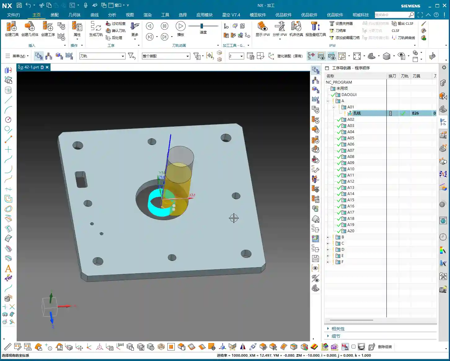
    Rough Milling the Center Slot: Aggressive Machining for Initial Material Removal

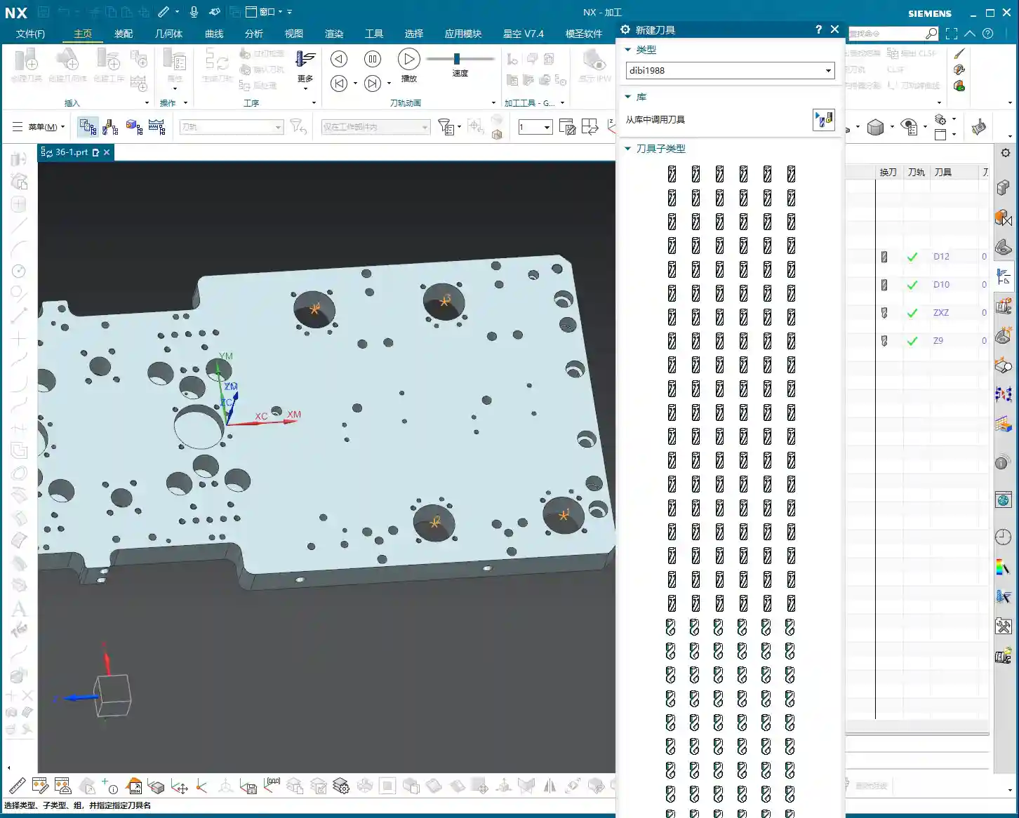
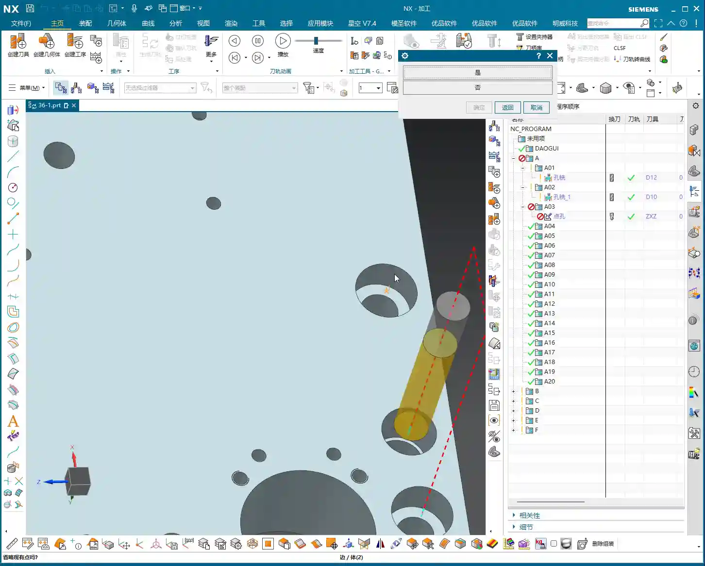
    For this slot, we’ll use ‘Hole Milling,’ which is essentially Slot Milling. Since it’s roughing, we can use a larger tool, but you must consider chip evacuation and cutting forces.

    • Insert operation, select HOLE_MILLING.
    • Specify feature hole, select our center slot.
    • Tool: I’ll choose a Φ26 end mill. To mill a 51mm wide slot with a Φ26 tool, you’ll need multiple passes or multiple levels to ensure smooth chip evacuation and prevent excessive cutting forces.
    • Cutting depth: The blueprint shows 10mm, but for stability and final accuracy, we’ll rough mill to 9.5mm. This leaves a 0.5mm stock allowance for subsequent finishing, resulting in less workpiece deformation and a better surface finish.
    • Optimize toolpath: Remember to adjust the entry method – helical or ramp entry. Don’t plunge straight down; that can lead to aggressive engagement and break the tool!

    Master Wang’s Tip: Don’t just trust the software simulation; you need to observe the actual cutting sparks and listen to the sound to make judgments. Excessive sparks or a dull, heavy sound definitely indicate aggressive cutting. Adjust your feed rate and spindle speed immediately!

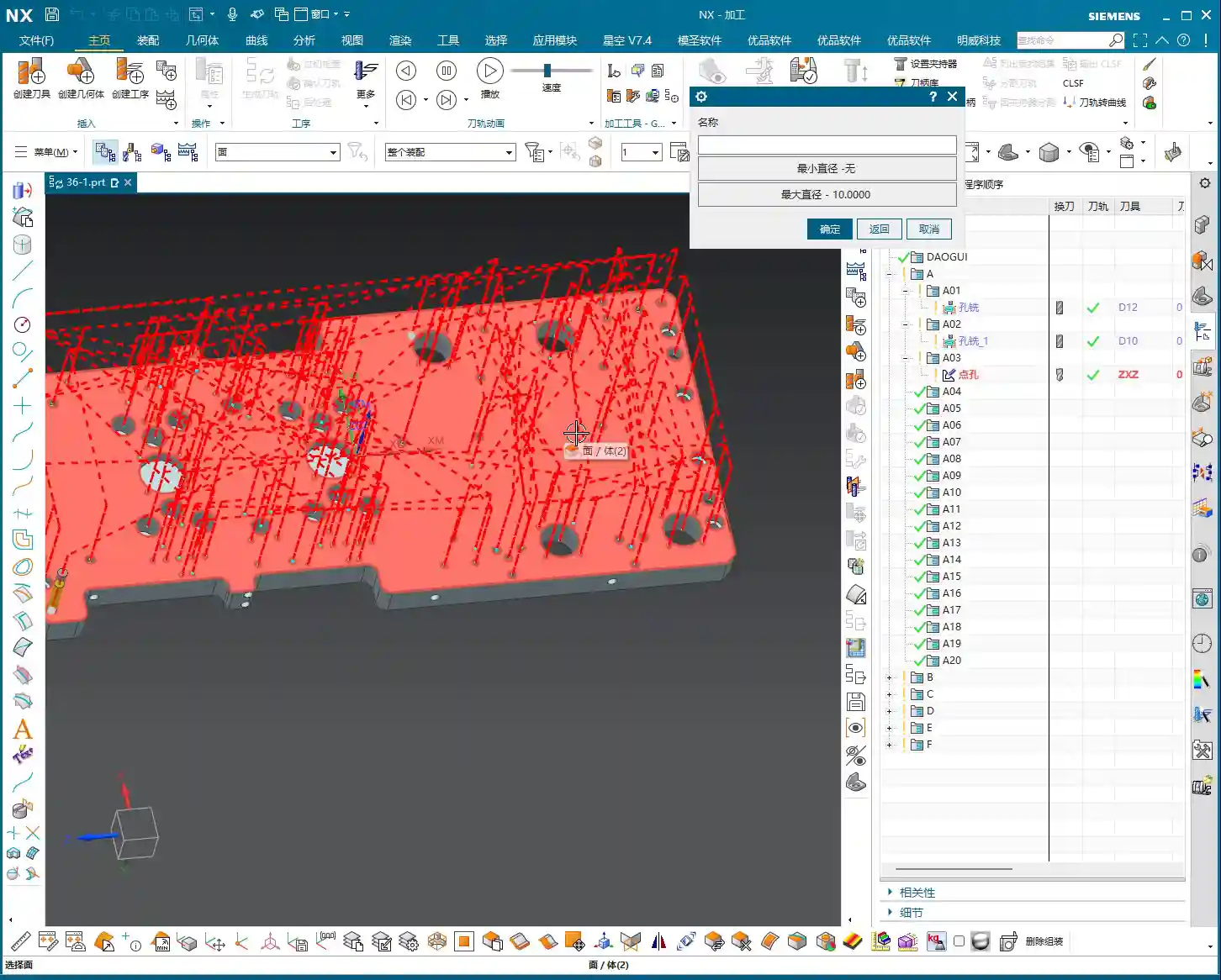
    Spot Drilling for Positioning: Precise Start for Drilling, Preventing Runout

    Spot drilling creates a guide for the drill. Without it, the drill is prone to wandering, especially for holes with a high length-to-diameter ratio. It’s a simple step, but never skip it.

    • Insert operation, select SPOT_DRILLING.
    • Specify feature hole, select all remaining round holes except the slot we just milled.
    • Tool: Use a center drill, typically 60- or 90-degree.
    • Depth: A 2-3mm depth is sufficient; its main purpose is positioning.

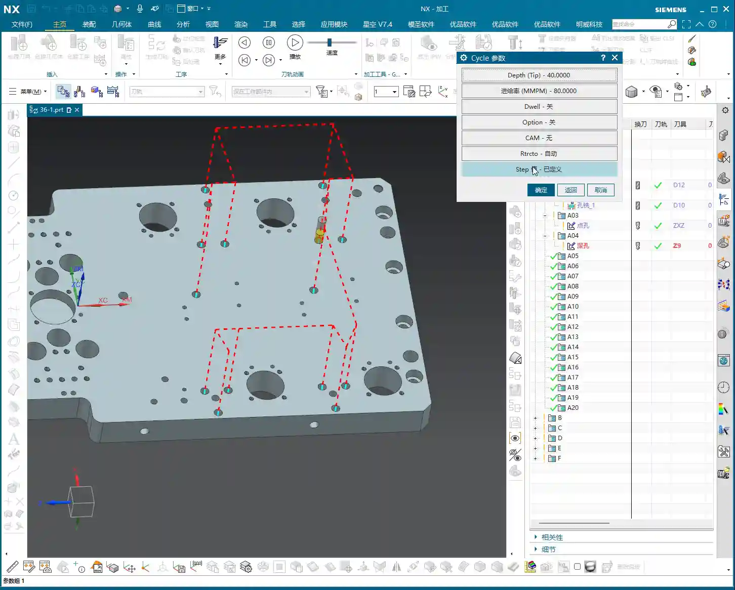
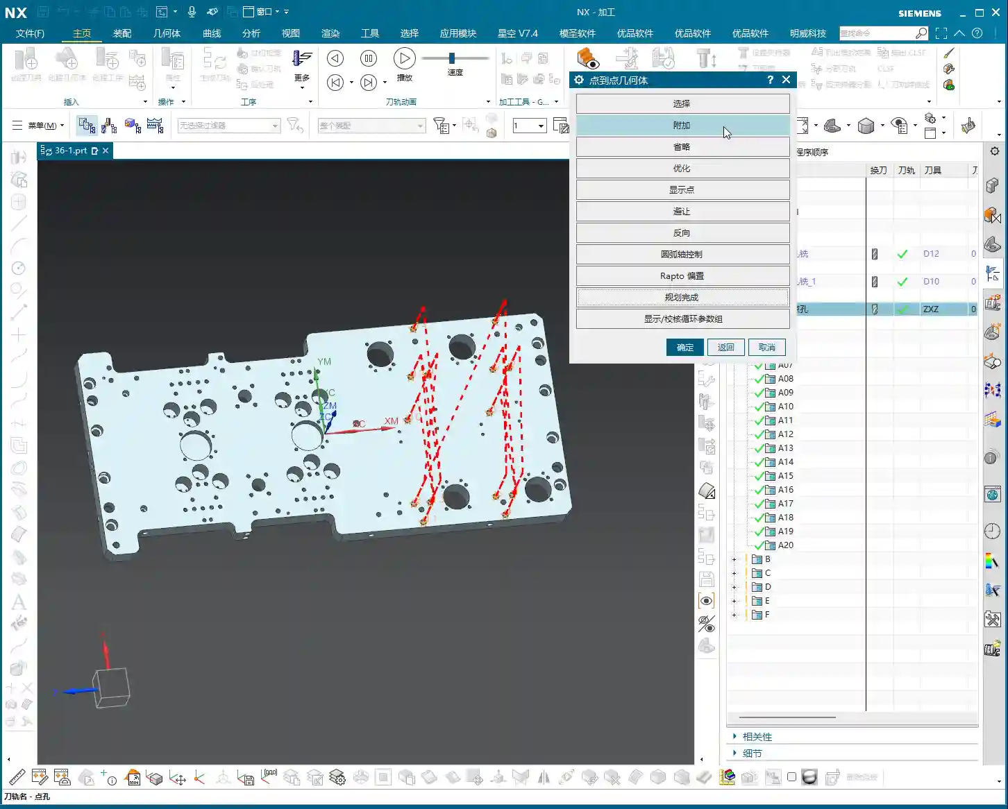
    Drilling Operations: Appropriate Depth and Judicious Stock Allowance

    Drilling is a core operation. Holes of different diameters and purposes require different drilling strategies.

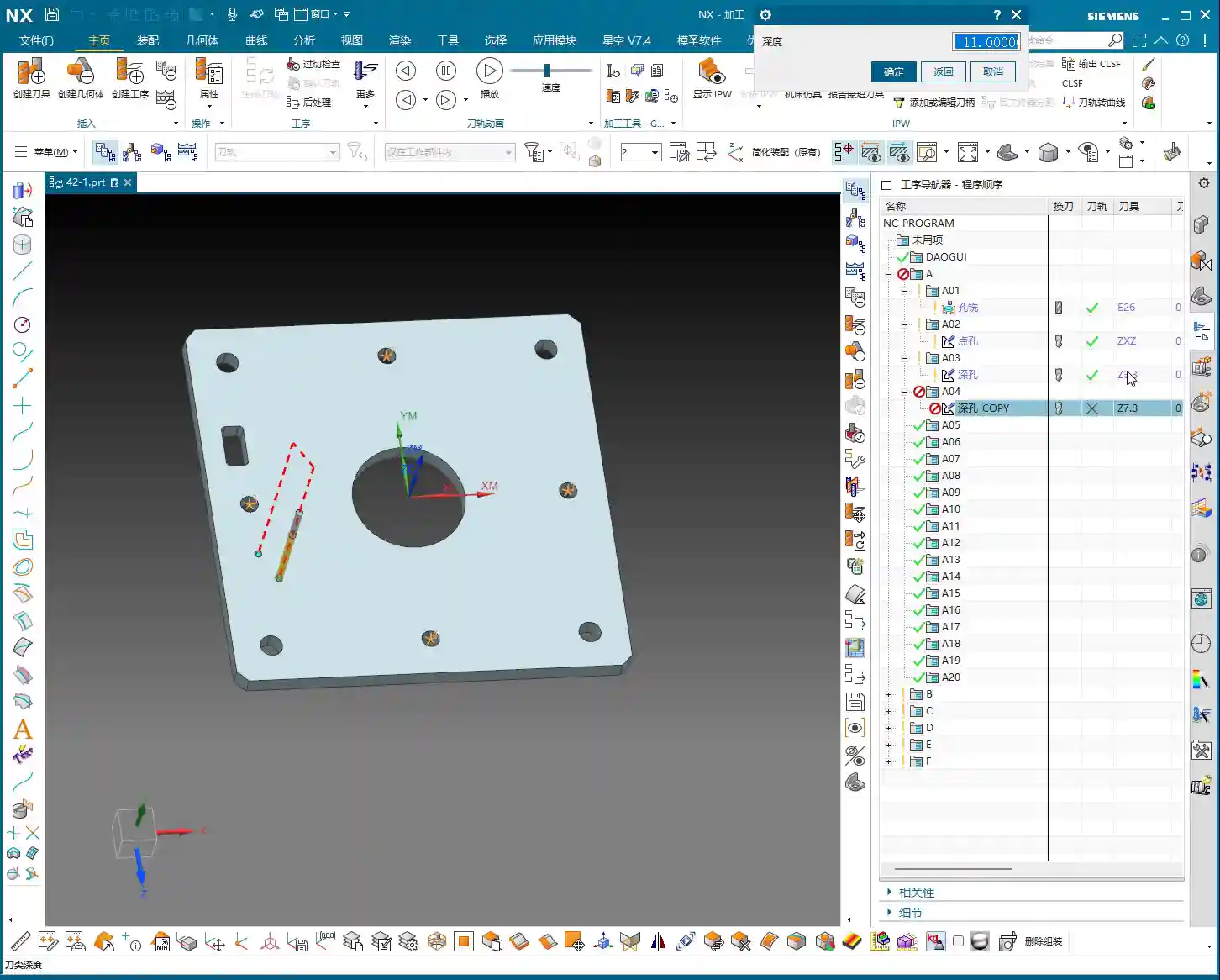
    M4 Thread Pilot Hole (Φ3.3)

    • Copy the spot drilling operation, change to DRILLING.
    • Select the M4 threaded hole locations.
    • Tool: Use a Φ3.3 twist drill.
    • Depth: To ensure effective tapping, we’ll drill slightly deeper than the design depth, for example, to a depth of 11mm (design depth 9mm).

    Φ8 Clearance Hole Pilot Hole (Φ7.8)

    • Copy the M4 drilling operation.
    • Select the Φ8 clearance hole locations.
    • Tool: Use a Φ7.8 twist drill. Pay close attention here: I’ve left a 0.2mm stock allowance. Why? Because Φ8 clearance holes might have higher precision and surface quality requirements. Leaving some allowance facilitates subsequent reaming or boring for finishing. If high precision isn’t critical, a direct Φ8 drill bit would also work.
    • Depth: Drill slightly deeper, for example, 11mm. Since it’s a through hole anyway, a slight over-drill won’t cause issues.
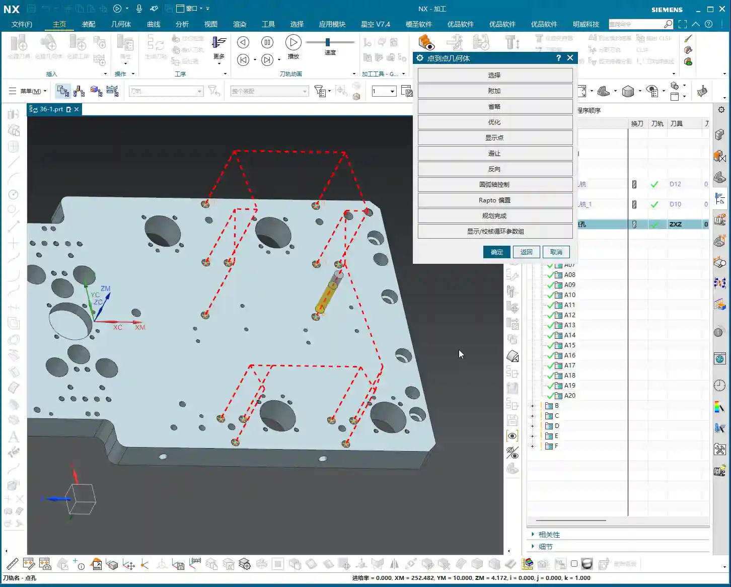
    Φ10 Through Holes

    • Copy the Φ8 drilling operation.
    • Select the Φ10 through hole locations.
    • Tool: Use a Φ10 twist drill.
    • Depth: Similarly, drill slightly deeper to 13mm to ensure complete penetration.

    Master Wang’s Tip: When drilling deep holes, always enable chip evacuation, also known as peck drilling. Parameters must be set appropriately. The Stepdown per peck shouldn’t be too large; otherwise, the drill bit can easily break, and the hole might drift. The G83 command on the machine is precisely for this purpose.

    Chamfering: Aesthetic and Functional

    Chamfering not only makes the part look better but also removes burrs and facilitates assembly. It’s a small task, but don’t overlook it.

    • Insert operation, select CHAMFER_MILLING.
    • Specify feature hole, select all holes requiring chamfering.
    • Tool: Use a chamfer tool, I typically use an 8mm one.
    • Depth: Depending on the chamfer size, a chamfer depth of approximately 1mm is usually sufficient. If the hole depth is 9mm and the chamfer depth is programmed to 11mm, the chamfer tool will travel deep into the hole, ensuring all burrs are removed from all holes.

    Finish Milling / Boring the Center Slot: Achieving Dimensions, Ensuring Precision

    The previous hole milling was roughing. Now we need to perform finishing to ensure the slot’s dimensions and surface quality.

    • Insert operation, select BORING. Although this is a slot, the boring operation in Siemens NX can also be used for slot finishing.
    • Specify feature hole, select the center slot.
    • Tool: For finishing, use a Φ51 T-slot cutter or end mill for side milling, or a suitably sized flat-bottom end mill for the finishing toolpath. Since it mentions a Φ51 boring operation, we’ll proceed with that concept.
    • Depth: Set to 10mm, which is 0.5mm deeper than the rough milling depth of 9.5mm, to remove the remaining stock allowance.

    Master Wang’s Tip: You need to be aware of tool wear during finishing operations. Even slight wear can lead to dimensional deviations. Therefore, regularly inspect your tools and apply compensation when necessary. In Siemens NX post-processing, you must know how to use the G41/G42 tool compensation commands; these are crucial for ensuring precision!

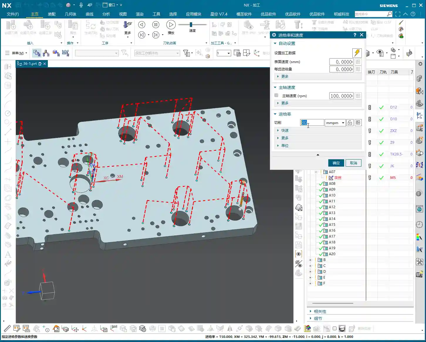
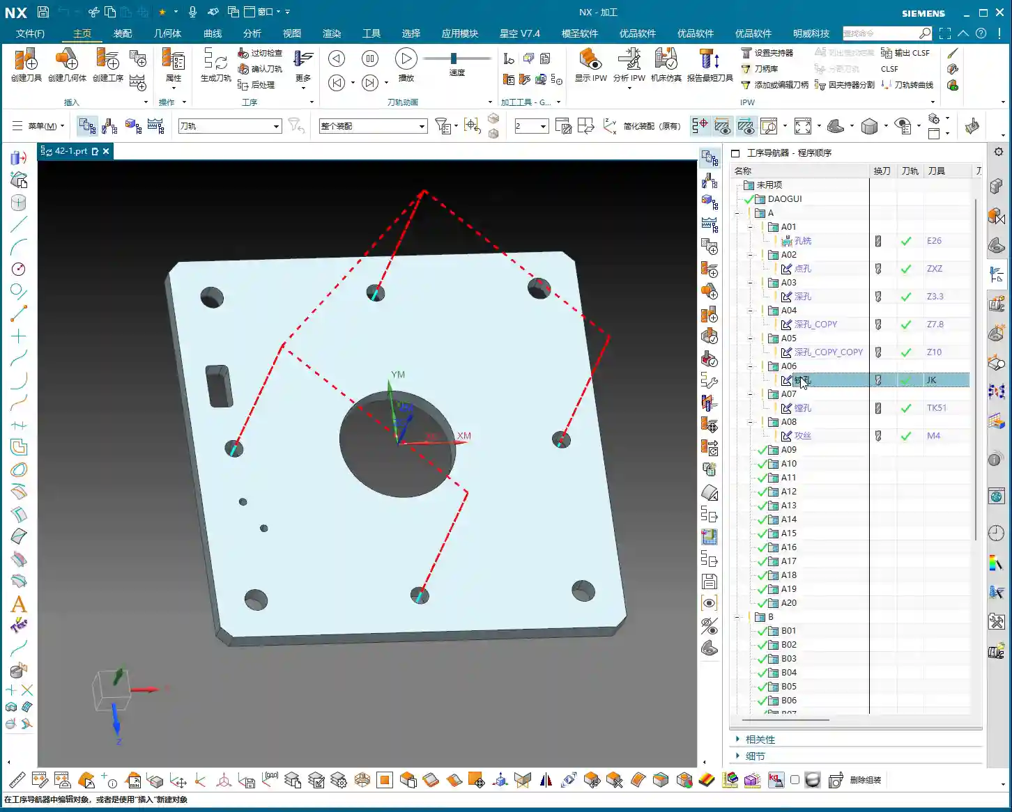
    M4 Thread Tapping: Even Force for Intact Threads

    Tapping is a delicate operation; a poor job will ruin the hole. For M4 threads, the pitch is 0.7mm.

    • Insert operation, select TAPPING.
    • Specify feature hole, select the M4 thread pilot hole locations.
    • Tool: M4x0.7 tap.
    • Pitch: 0.7mm. Siemens NX will automatically calculate the feed rate.
    • Depth: Slightly deeper than the drilled depth, for example, 11.5mm, to ensure complete threads.

    Master Wang’s Tip: Tapping speed should not be fast, especially for blind holes. Use slow feed and retract speeds to ensure proper chip evacuation. If you’re tapping aluminum, you can go a bit faster. For steel, it’s safer to go slower. Tap material and coolant selection are also crucial factors affecting tap life and thread quality.

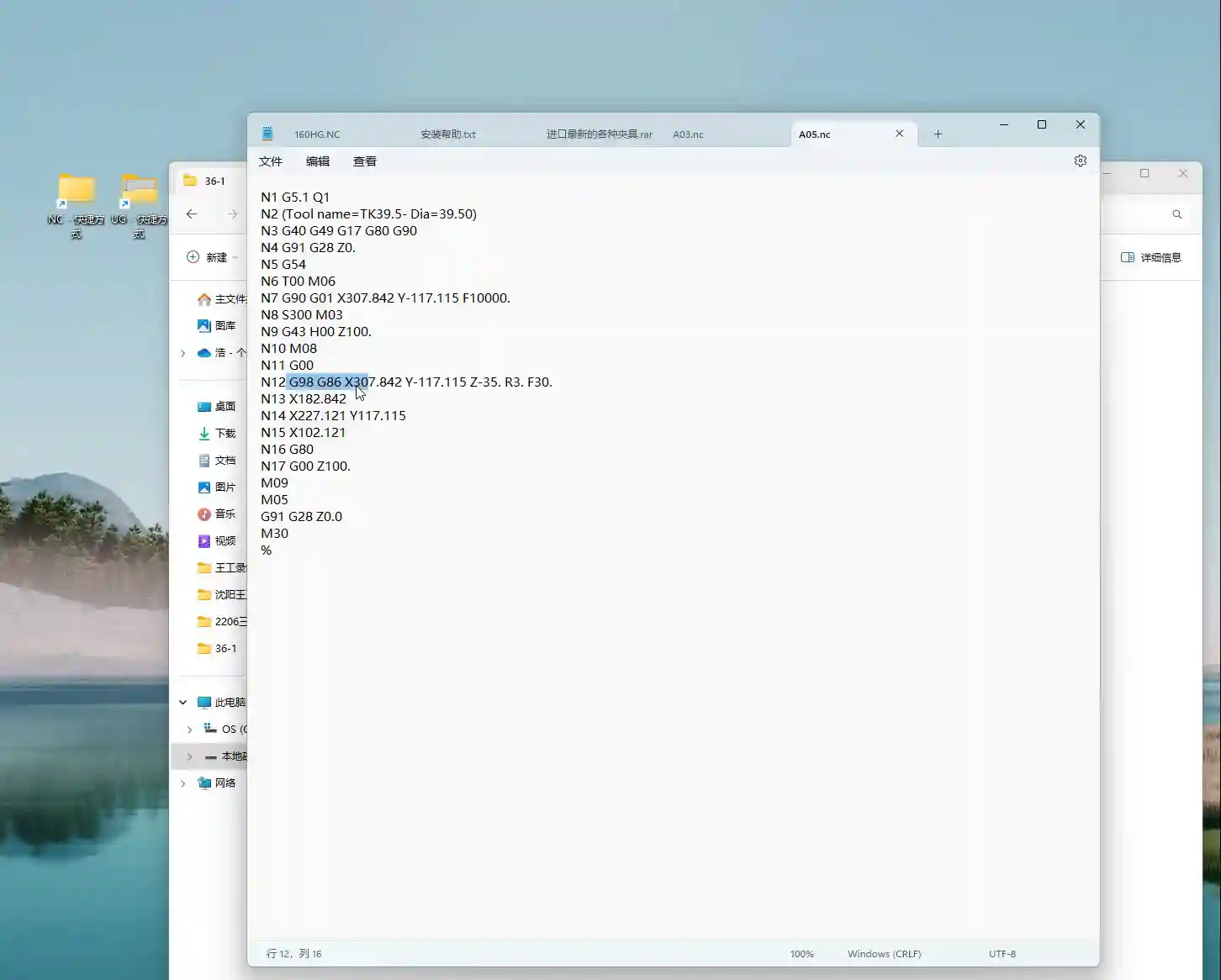
    Process Verification and Saving: Critical Final Steps

    Once all operations are programmed, you must run a simulation to check for overcuts, air cuts, or unreasonable toolpaths. Run the simulation in Siemens NX to visualize the toolpath and cutting process. Once everything looks good, save your work immediately!

    • Right-click on the operation, select 3D Dynamic Simulation, and simulate the entire machining process.
    • Check if the toolpath is smooth and if there’s any interference.
    • Confirm that all stock allowance has been properly removed.
    • Finally, save the file! Don’t let a system crash wipe out all your hard work.

    Summary: Pitfall Avoidance Guide

    1. Accurate WCS Positioning is Crucial: The Work Coordinate System is the foundation. If it’s wrong, all subsequent toolpaths will be useless. Always carefully indicate the part and confirm your zero point.
    2. Tool Selection and Parameter Matching: For different materials and operations, the tool’s material, coating, and geometry must be correctly chosen. Cutting parameters (spindle speed, feed rate, Depth of Cut, Stepover) cannot be simply copied; they must be adjusted based on actual conditions. It’s better to be conservative than to take risks.
    3. The Art of Stock Allowance: Always leave a reasonable stock allowance between roughing and finishing passes. If the allowance is too small, the finishing tool won’t have enough material to engage; if it’s too large, the finishing tool will be overloaded, leading to deflection or breakage.
    4. Depth Control is Key: Especially for blind holes and threaded holes, depth must be precise. Drill slightly deeper during drilling, and ensure sufficient effective thread depth during tapping.
    5. Never Blindly Pursue Speed: Production efficiency is important, but quality is paramount. Improve efficiency by optimizing toolpaths, minimizing air cuts, and selecting appropriate cutting parameters, rather than simply increasing speed.
    6. Simulation is Essential: Always perform a simulation after completing each programming task. Don’t be lazy; this step can help you uncover many potential problems, preventing machine crashes and scrapped workpieces.
    7. Accumulate Experience: Book knowledge is fundamental, but the challenges encountered in actual operation are the best teachers. Observe, record, and reflect constantly, turning every lesson learned into your personal wealth.

    👤 About the Author:
    The author is a veteran CNC machining professional with 15 years of industry experience, specializing in UG NX programming. This article is an original work representing personal practical insights.

    ⚠️ Copyright Notice: Unauthorized reproduction or distribution without prior communication is strictly prohibited.

  • Master Wang’s Hands-On Guide: Siemens NX CNC Machining – Practical Essentials and Pitfall Avoidance

    📝 Key Takeaways: Master Wang personally shares the practical essentials of Siemens NX CNC drilling, boring, reaming, and tapping. He delves into the programming and operational keys for each hole machining process, from G-code and Q-value chip evacuation to feed rates, spindle speeds, and tool selection. He thoroughly analyzes the F=S*P calculation for M5 tapping, emphasizing the critical importance of pilot hole accuracy, tool rigidity, and chip evacuation. Rejecting theoretical talk, the focus is on practical machine operation and cost efficiency, helping you avoid common pitfalls like tool breakage and scrapped parts, thereby improving machining accuracy and efficiency.

    Hello everyone, I’m Master Wang. Today, we’re diving deeper into some core machining processes: drilling, boring, reaming, and tapping. Don’t underestimate these fundamental operations; each step holds significant intricacies. A misstep can lead to scrapped parts, or even broken tools. Listen closely. Today, I’ll break down the practical insights I’ve gathered over years of hands-on experience.

    Drilling: The First Step in Part Machining

    Drilling is the starting point for part machining. In Siemens NX, you’ll select Sense or Drill – the name isn’t as important as understanding its function. Setting the hole position and depth in NX is similar to spot drilling. However, drilling introduces a critical parameter: the Q-value, which is the pecking depth, used for chip evacuation. Especially for deep holes, an incorrectly set Q-value can lead to poor chip breaking, severe chip packing and tool breakage, or even damage to the hole wall!

    When setting the depth in NX, like the 40mm shown in the video, remember it’s just an example. In actual machining, the depth must account for the tool tip angle. For instance, if you’re drilling an M8 hole with an effective depth of 20mm, when setting the depth in NX, you need to add the length of the tool tip to ensure the full hole diameter is achieved at the required depth. Siemens NX’s G83 cycle (deep hole drilling) repeatedly pecks in and retracts to evacuate chips using the Q-value. With each retraction, make sure the chips are fully cleared. Don’t just rely on software simulations; observe the cutting sparks and the actual chip formation!

    Practical Tips

    • Tool Selection: High-speed steel (HSS) and carbide drills each have their characteristics. Carbide is suited for high-speed, high-efficiency operations but has slightly less rigidity and higher machine requirements. For tough materials like titanium alloys and high-temperature nickel-based alloys, specialized custom drills with specific coatings and geometries are essential.
    • Feed and Spindle Speed: Listen up, it’s better to go a bit slower than to rush too fast. Especially when drilling blind holes, decelerate as you approach the bottom to prevent chipping the cutting edge. Chip evacuation must be prompt, and coolant should be generously supplied, directed right into the cutting zone.
    • G-code: The Siemens NX post-processor will output G83 Z-Depth R-Retract Plane Q-Peck Depth F-Feed rate. Note that the Z-value must include both the safety distance and the tool tip length.

    Boring: The ‘Scalpel’ for Precise Hole Sizing

    Boring, simply put, is the secondary machining operation for drilled holes to achieve higher precision and surface finish. Drills are for roughing; boring tools are for finishing. In Siemens NX, you select Boring, and the resulting G-code is typically G86 (spindle stop and retract) or G85 (spindle forward and retract) – pay attention to their differences. Choosing the correct boring tool and cycle determines the final quality of the hole.

    The key to boring is tool rigidity and overhang length. Shorter, thicker boring bars offer better rigidity, resulting in higher hole precision and less susceptibility to chatter. For deep holes, where depth exceeds three times the diameter, specialized anti-vibration boring bars or even tungsten carbide boring bars are necessary. When setting up boring tools in Siemens NX, precision in dimensions is crucial. For instance, if the video shows a 39.5mm hole, I’d create a 39.5mm boring tool. However, in actual machining, especially for finish boring, Tool Offsetting is extremely important. If you need to bore to an H7 tolerance, adjusting the tool offset by ±0.005mm (approx. ±0.0002 inch) should be routine for you.

    Practical Tips

    • Multi-Stage Machining: Finish boring typically involves two steps: rough boring and finish boring. Rough boring uses larger stock removal and faster feeds; finish boring uses minimal stock removal, slower feeds, and higher spindle speeds, with the goal of achieving a superior surface finish.
    • Tool Naming: While you can select any tool type in Siemens NX, the post-processed program’s tool name must correspond to the actual physical tool. Otherwise, if the operator sees a D100 boring tool in the program but you’ve loaded a D10 tool, you’re asking for major trouble! This is a practical pitfall not taught in textbooks.
    • G-code: G86 Z-Depth R-Retract Plane F-Feed rate. Note that G86 stops and orientates the spindle at the bottom of the hole before rapid retract, preventing tool marks. G85, on the other hand, retracts with the spindle still rotating forward.

    Reaming: Ensuring Both Dimensional Accuracy and Surface Finish

    Many people confuse reaming with boring. Boring can correct hole diameters and eccentricity, offering broader applications. Reaming is primarily used for final finishing of pre-drilled or pre-bored holes, making the final push for dimensional accuracy and surface roughness. It cannot correct positional errors, but it improves the hole’s roundness, cylindricity, and surface quality.

    In Siemens NX, select Reaming, and the generated G-code is typically G85. Remember, the stock allowance for reaming must be small, typically 0.05-0.15mm (approx. 0.002-0.006 inch) per side. Too much allowance can lead to reamer wear, chipping, or even oversized holes. The feed rate should be slow, and the spindle speed high. This differs somewhat from drilling and boring. Too slow, and you risk chatter marks; too fast, and the reamer won’t properly cut the allowance, resulting in a poor surface. Coolant must be abundant to ensure chip evacuation and cooling.

    Practical Tips

    • Reamer Selection: Reamers come in hand reamer and machine reamer types, as well as straight flute and helical flute designs. Select the appropriate reamer based on the hole type and material. Pay special attention to the chamfer on the leading edge, as it directly impacts reamed hole quality.
    • Siemens NX Programming: Remember to properly set the reamer’s entry and exit paths to ensure smooth tool engagement and retraction, preventing secondary scratches on the hole wall.
    • G-code: G85 Z-Depth R-Retract Plane F-Feed rate. G85 maintains forward spindle rotation at the bottom of the hole and retracts with the spindle still rotating forward, which prevents tool marks on the hole wall, making it suitable for finishing operations.

    Tapping: Adding Threads to Your Part

    Tapping is the process of machining threads into a hole, preparing it for assembly. Here, two parameters are paramount: pilot hole size and pitch.

    In Siemens NX, select Tapping. The standard tapping cycles are G84 (right-hand thread) or G74 (left-hand thread). Most modern machines support Rigid Tapping, where the spindle and feed are synchronized, resulting in high accuracy and reduced tap breakage.

    Practical Tips

    • Calculating the Pilot Hole: Taking an M5 thread as an example, with a pitch of 0.8mm. The pilot hole diameter is generally the nominal diameter minus the pitch. For an M5 thread, this would be 5 – 0.8 = 4.2mm (approx. 0.165 inch). This pilot hole size is critical; get it wrong, and the part is scrap! Too small, and the tap will easily break; too large, and the thread depth will be insufficient, failing to meet strength requirements.
    • Setting the Feed Rate (F-value): F = Spindle Speed (S) × Pitch (P). If S is 100 RPM and the pitch is 0.8mm, then F would be 80 mm/min. Don’t just blindly input parameters in Siemens NX; this formula must be second nature! Otherwise, if the tool wears down and the F-value isn’t adjusted accordingly, you’re looking at tap breakage.
    • Siemens NX Programming: Ensure the correct tap tool is selected and verify the tapping depth. When tapping blind holes, always leave chip clearance; don’t drill to the absolute bottom. The tap should also slightly lift at the bottom to prevent chip accumulation leading to tap breakage.
    • Cooling and Lubrication: Tapping is a heavy cutting operation, especially for steel. Ensure ample coolant is supplied to significantly extend tap life and improve thread quality.
    • G-code: G84 Z-Depth R-Retract Plane F-Feed rate S-Spindle Speed. Remember, the F-value must match S and P, otherwise tap breakage is inevitable.

    Summary: Pitfall Avoidance Guide

    Listen closely, whether it’s drilling, boring, reaming, or tapping, always remember these Master Wang’s Ironclad Rules for Avoiding Pitfalls:

    • Material is Fundamental: Different materials require corresponding adjustments to tooling, spindle speed, feed rate, and coolant. For high-hardness, high-toughness materials, don’t just think about brute-force speed. First, ask yourself: Is this a specialized tool?
    • Fixturing is a Prerequisite: The workpiece must be securely clamped and fixtured with sufficient rigidity. Vibration is the enemy of both accuracy and tool life! No matter how perfect your Siemens NX model looks, if it’s not stable on the machine, it’s all for nothing.
    • Tooling is Core: Selecting the appropriate tool and sharpening it properly are fundamental skills. Grinding custom tools is an expertise for experienced machinists like us – learn and ask more! Don’t use one tool for every job; that’s working foolishly, not cleverly.
    • Parameters are the Soul: Feed rates, spindle speeds, depths, and Q-values in Siemens NX programming aren’t set arbitrarily. They must be adjusted based on experience, tool manufacturer recommendations, and actual machine conditions. Don’t just rely on software simulations; observe the cutting sparks, listen to the cutting sound, and even smell the cutting chips – that’s real expertise!
    • Precision is Lifeline: When facing ±0.005mm (approx. ±0.0002 inch) level precision issues, don’t immediately blame the machine. Check your fixturing, tool wear, coolant, and tool offset settings. Often, process adjustments can resolve the problem.

    Finally, remember that machining efficiency and cost are always critical considerations. While ensuring quality, you must continuously think about how to optimize tool paths, minimize air cuts, and extend tool life. Alright, that’s all for today. Go digest this information thoroughly, and next time we’ll discuss something even more in-depth!

    👤 About the Author:
    The author is a veteran CNC machining professional with 15 years of industry experience, specializing in UG NX programming. This article is an original work representing personal practical insights.

    ⚠️ Copyright Notice: Unauthorized reproduction or distribution without prior communication is strictly prohibited.

  • Siemens NX Spot Drilling, Drilling, and Tapping: Practical Strategies for Doubled Efficiency and Pre

    📝 Key Takeaways: **

    Siemens NX Spot Drilling and Hole Machining Optimization in Practice

    Master Wang’s Insights: The Intricacies of Hole Machining

    To all seasoned pros and aspiring apprentices, I’m Master Wang. Today, let’s cut the fluff and get straight to the practical tips, discussing the “Spot Drilling” operation in Siemens NX. Don’t let its simplicity fool you; there’s a lot more to it than meets the eye. Mastering this will save you significant machining time and ensure your part’s precision. Spot drilling, drilling, and tapping generally follow the same operational logic in Siemens NX. Today, we’ll start with Spot Drilling (G81) to thoroughly understand this logic, and then all other hole machining operations will come naturally!

    Hole Machining Cycle Overview (G-Code)

    The hole machining cycles in Siemens NX essentially generate the corresponding G-code in the background for you. It’s crucial to understand:

    • Spot Drilling: G81, typically used for locating counterbore holes, or for direct through-drilling of small holes.
    • Drilling: G83, for deep hole drilling with chip break.
    • Boring: G86, for finish boring, commonly used to improve hole accuracy and surface finish.
    • Reaming: G85, for finishing already drilled holes, improving dimensional accuracy and cylindricity.
    • Tapping: G84, for machining internal threads.

    These commands have similar interfaces, and their principles are all top-down. So, if we thoroughly understand spot drilling, the others will fall into place naturally.

    Spot Drilling Operation: Selection is Key

    Alright, open Siemens NX and locate the “Spot Drilling” operation. The first step is to select the holes you want to machine.

    Basic Selection: Specify Feature Group and Selection Modes

    After selecting “Specify Feature Group,” you’ll enter the hole selection interface. Here are a few options you need to understand:

    • Select: This is the most frequently used method. You can directly click on the edge of the hole to select it. Siemens NX will automatically identify and mark it.
    • The Trick to “Yes” or “No”: When you click the “Select” button again, the system will ask, “Delete existing selection?”

      • If you choose “Yes”: It will delete all previously selected holes and allow you to reselect. If you want to clear your current selection and start over, click “Yes.”
      • If you choose “No”: It will retain your previously selected holes and allow you to add new ones. This is the most common method; typically, you’ll click “No” to append to your selection.

    • Add: This function is essentially the same as choosing “No” with the “Select” option—both allow you to append to an existing selection. In my experience, just using “Select” and then clicking “No” is sufficient; there’s no need to specifically click “Add,” as it can sometimes be confusing.

    Advanced Selection: General Point and All Holes on Face

    Besides manual point selection, Siemens NX also offers more intelligent selection methods, especially when a part has many holes, which can significantly boost efficiency.

    • General Point:

      This option allows you to directly select any point in space as the machining location. Remember, Siemens NX will only register where you click; it won’t determine if your selected point is a “true” hole feature.

      Master Wang’s Warning: This is where problems can arise! If you click in the middle of a face or some odd location, it will still generate a spot drilling program. So, when using “General Point,” always ensure you’re precisely clicking on the intended machining point. Don’t just rely on the software simulation; visualize the chip formation and actual outcome.

    • All Holes on Face:

      This is a powerful feature! When a face has numerous holes, you can directly select that face, and Siemens NX will automatically identify and select all holes on it.

      What’s even better is that you can apply diameter filtering here. For instance, if you want to spot drill Ø5mm holes, you can set “Minimum Diameter” to 5 and “Maximum Diameter” also to 5. This way, it will only select the Ø5mm holes on that face.

      Practical Tip: Often, blueprints specify a face with many holes of different diameters, but you only need to machine a specific type. In such cases, using “All Holes on Face” combined with precise “Minimum Diameter” and “Maximum Diameter” settings will help you quickly filter for your target holes, saving you the hassle of individual selections and instantly doubling your efficiency!

    Deletion: Removing Unwanted Holes

    What if you accidentally selected too many, or some holes you no longer wish to machine? Use the “Delete” function.

    • Delete/Exclude: After clicking this option, if you then click on already selected holes, those holes will be removed from the machining list.
    • Master Wang’s Reminder: After deleting holes, you absolutely *must* regenerate the toolpath! Otherwise, the program will still follow the old path, rendering your deletion useless. This will lead to rework, wasting both time and effort.

    Toolpath Optimization: The Art of Balancing Efficiency and Cost

    Once the holes are selected, the next step is optimization! This is of utmost importance, especially when you’re machining more than two holes. Without optimization, the tool will wander aimlessly across the part, making unnecessary rapid moves (air cuts). That’s time and money wasted!

    Siemens NX Optimization Steps and Logic

    Optimization aims to make the tool travel the shortest path, reduce non-cutting moves, and improve machining efficiency.

    1. Click Optimize.
    2. In the dialog box that appears, select Shortest Path. This is the most commonly used optimization strategy.
    3. Click the Optimize button again.
    4. Click Accept.
    5. Finally, regenerate the toolpath, and you’ll see a clear, logically sequenced machining order with the shortest path.

    Master Wang’s Take: With an optimized toolpath, the tool will move from the closest hole to the next closest, avoiding unnecessary long-distance rapid moves (air cuts). This step is *mandatory* every time you select holes, especially if there are more than a couple! This is a hard-earned truth not taught in textbooks, but one that will save you money on the shop floor! Don’t just assume everything is fine if the software simulation shows no errors; a few extra rapid moves can easily waste your entire day’s production.

    Clearance: Ensuring Safe Machining

    Although “Clearance” wasn’t extensively covered in the audio, as a master machinist, I have to bring it up. On complex parts, especially when there are fixtures or bosses, the tool’s entry/exit paths and tool change positions must all account for clearance.

    • Master Wang’s Reminder: Setting clearance parameters in Siemens NX directly impacts whether the tool will crash into the workpiece or fixture. It’s always better to use a slightly higher safe clearance than to risk crashing the tool for a little speed. In practice, clearance heights must consider fixture height, workpiece height, tool length, and machine travel limits. This area is prone to tool crashes; don’t just admire the pretty model—a real machine crash is a brutal and costly lesson!

    Summary: Pitfall Avoidance Guide

    1. Choose “No” to append, “Yes” to clear: Remember this logic when selecting multiple holes to avoid accidental deletions or duplications.
    2. Use “General Point” with caution: Only use it when you genuinely need to specify an arbitrary point for machining. Otherwise, accidental clicks can lead to useless toolpaths or even tool crashes.
    3. Cleverly use diameter filtering: When facing a plane with many holes, leverage “Minimum/Maximum Diameter” to quickly filter target holes, significantly boosting efficiency.
    4. Always regenerate after deletion: Any changes to your selection (e.g., deleting holes) require toolpath regeneration to take effect.
    5. Optimization is Productivity!: For more than two holes, toolpath optimization is mandatory! This is crucial for boosting efficiency and reducing the cost of non-cutting moves.
    6. Don’t skimp on clearance parameters: Safety first! Ensure the tool avoids all obstacles during movement, especially during tool changes and rapid moves. This directly impacts the lifespan of your machine and tools.

    Today’s practical insights from Master Wang are hard-won lessons I’ve accumulated over 15 years of hands-on experience on the shop floor. Theoretical knowledge is just the foundation; practical experience is true gold. I hope all of you can apply what you’ve learned, master Siemens NX, execute your jobs flawlessly, and become true experts on the shop floor!

    👤 About the Author:
    The author is a veteran CNC machining professional with 15 years of industry experience, specializing in UG NX programming. This article is an original work representing personal practical insights.

    ⚠️ Copyright Notice: Unauthorized reproduction or distribution without prior communication is strictly prohibited.