Tag: NX Corner Cleanup

  • Siemens NX Corner Cleanup Combat Manual: Master Wang Unveils Toolpath Options & Parameter Optimizati

    📝 Key Takeaways: Master Wang shares practical NX Corner Cleanup techniques. From selecting a reference tool for corner cleanup to various cutting modes (Zigzag, Follow Part Outline, Zigzag-Up, Steep/Non-Steep), he thoroughly explains the characteristics and applicable scenarios for each toolpath. He specifically emphasizes combining “Alternate from Outside-In” with the “Smoothness” function to ensure excellent surface finish at part corner radii. Learn to identify yellow toolpath regions to avoid misjudgments and truly master the strategies not found in textbooks.

    The Core of Corner Cleanup — Understanding Reference Tool Corner Cleanup

    What is Reference Tool Corner Cleanup?

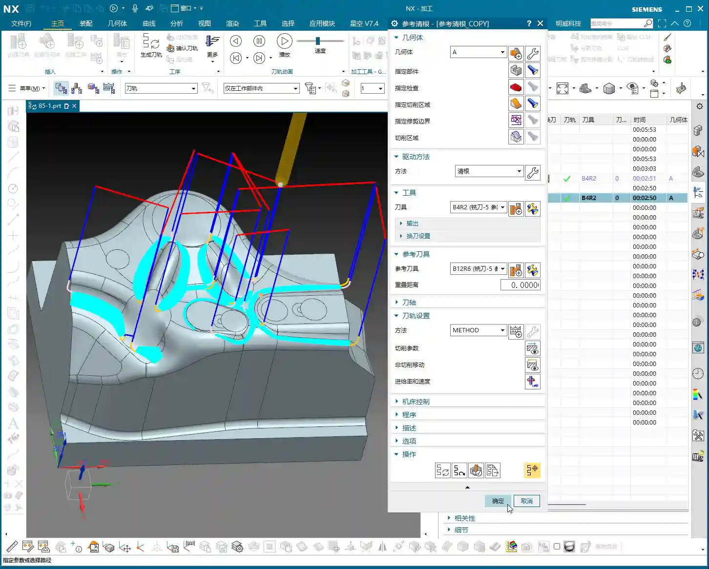
    Master Wang: Folks, it’s Master Wang here. Today, let’s talk about “Corner Cleanup” in NX. Don’t underestimate it; many quality issues in the workshop stem from these hard-to-reach corner radii. Our commonly used “Reference Tool Corner Cleanup,” as the name suggests, uses a “reference tool” larger than the current tool to identify areas that the previous tool couldn’t reach, and then a smaller tool is used for cleanup. This is a critical, core function in our NX programming, and you must master it thoroughly!

    Part Selection and Initial Setup

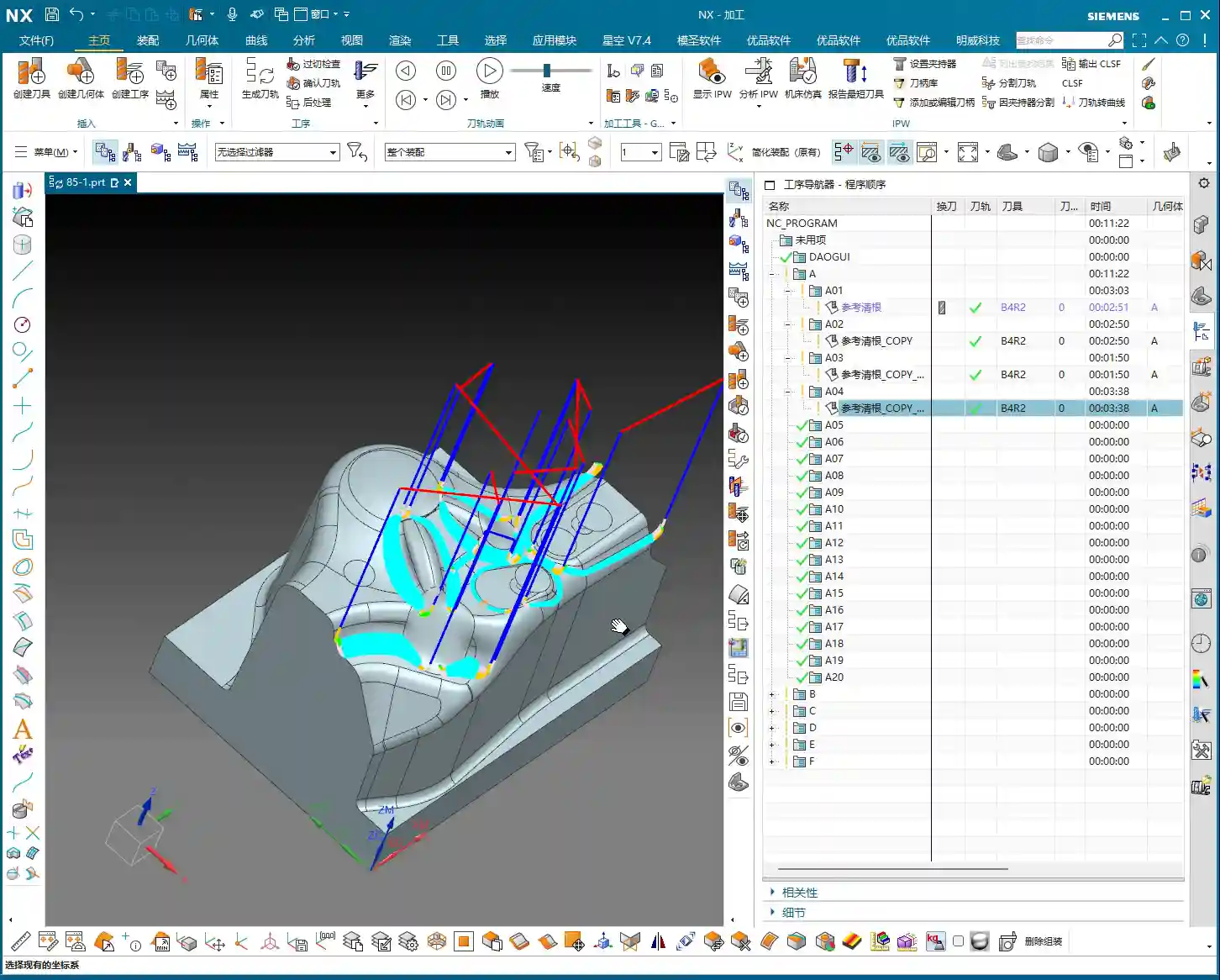
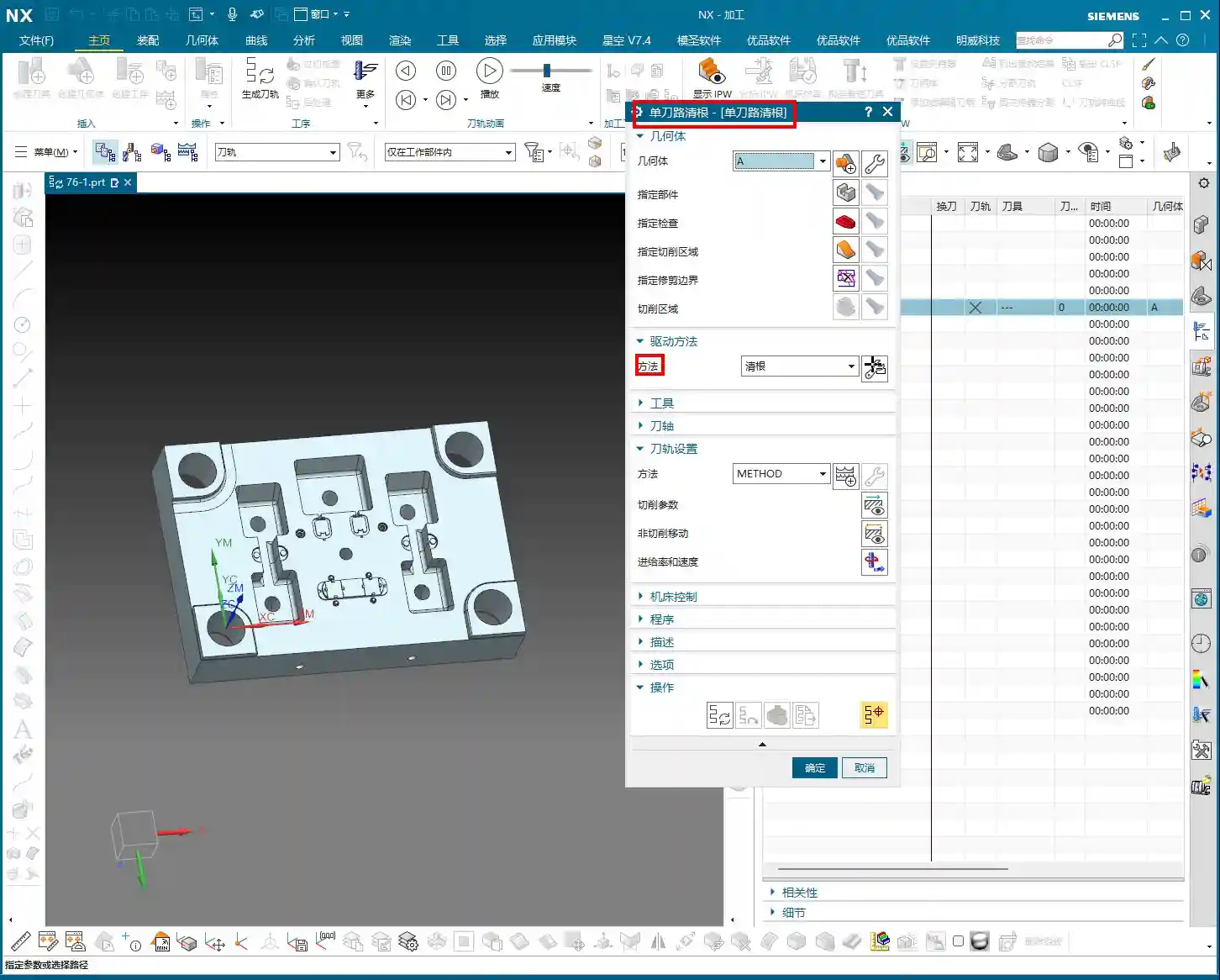
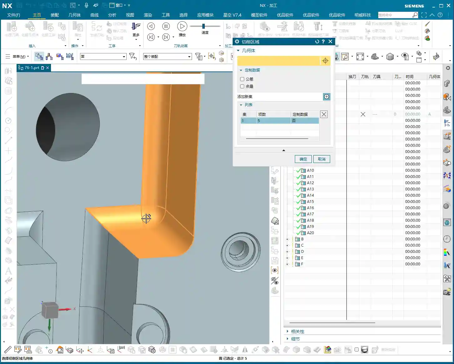
    Master Wang: Listen up! Step one in the operation is to first insert the “Operation,” then select “Reference Tool Corner Cleanup.” This is common knowledge, I’ve explained it countless times before. But there are two points you need to pay attention to:

    1. **Blank Definition**: Before starting any job, you **MUST define the blank clearly**. Otherwise, once the toolpath is calculated, you’ll either have an overcut or air cutting. Don’t make rookie mistakes!
    2. **Machining Area Selection**: When you encounter a part like ours, which has “sheet bodies,” don’t be foolish and select everything directly. You need to switch to “Only Select Faces” and then use “Box Selection” mode. This ensures you select the correct area, neither missing nor over-selecting. If you select too much, the program might calculate a bunch of yellow lines. Don’t panic, it’s not a program error, I’ll explain what’s happening later.
    3. **Tool Selection**: Which tool to choose? Youngster, for corner cleanup, just pick a common end mill that can reach into the corner radius. Here, the **specific tool model isn’t the main point; the key lies in the toolpath strategy and parameter settings**. That’s what determines the quality of your part!

    In-Depth Analysis of Corner Cleanup Strategies

    “Zigzag” Milling: The Foundation for Reliable Stock Removal

    Master Wang: The program we initially run often defaults to “Zigzag” milling. Simply put, this mode makes the tool move back and forth within the machining area, like plowing a field. It’s stable and removes material, but there’s a problem: the **”tool marks” can be quite noticeable**, especially on contoured surfaces. For parts requiring a high surface finish, you’ll need to look at other strategies. This is generally the entry-level method for corner cleanup; it gets the material out, but to achieve a smooth finish, you need to dig deeper.

    “Steep Up” Strategy: The Bottom-Up Finishing Approach

    Master Wang: “Steep Up” is the opposite of “Steep Down.” “Steep Down” cuts from top to bottom, using the tool’s bottom edge; “Steep Up,” on the other hand, **cuts from bottom to top, layer by layer upwards**. With this machining method, the tool first reaches the bottom, then lifts and cuts upwards from the bottom. This results in stable cutting forces and good chip evacuation. Let me tell you a trick: for areas with **small fillet radii** at the bottom, or where high surface finish is required on side walls, “Steep Up” can effectively reduce tool marks. This is because the final pass will lift from the bottom, allowing the tool to exit more smoothly, naturally leading to a better surface finish.

    “Follow Part Outline”: Flexible Approach for Sidewall Corner Cleanup

    Master Wang: Now, let’s talk about “Follow Part Outline.” As the name implies, this mode means the **tool’s side cutting edge follows the boundary, primarily addressing corner cleanup in sidewall regions**. With this method, the toolpath precisely conforms to the part’s boundaries, making it particularly effective for narrow, complex corner radii. For instance, if you need to clean up deep grooves or irregular slots, this method can thoroughly clean out dead spots. However, it also has a drawback: if the entire area is machined with this mode, efficiency might not be as high as “Zigzag.” So, you have to tailor your approach and not apply it indiscriminately.

    “Zigzag-Up”: An Efficient Strategy for Smooth Surface Corner Cleanup

    Master Wang: “Zigzag-Up” is a commonly used and highly effective strategy for processing contoured surfaces during corner cleanup. It combines the efficiency of “Zigzag” with the smoothness of “Up” cutting. Especially when combined with the **”Alternate from Outside-In”** cutting strategy, the results are even better! It starts from the periphery of the machining area and cuts inwards in a spiral, finally converging to the center, much like a snail shell. This approach **allows the cutting force to gradually decrease from outside to inside, which helps maintain tool life and machining stability**. Especially during finishing passes, it can produce perfectly round, smooth corner radii. For our contoured part today, this method is particularly suitable!

    Key Parameters and Practical Tips

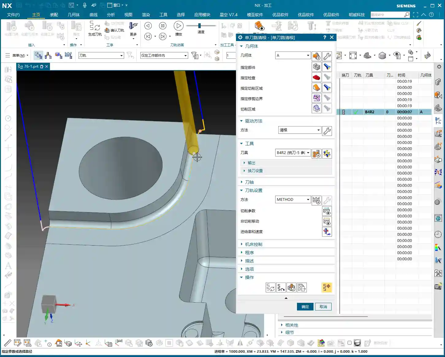
    The ‘Wrench’ Icon in Fixed Axis Contour Milling Parameters

    Master Wang: In NX, everything related to “Fixed Axis Contour Milling” has critical settings under that “wrench icon.” Our corner cleanup also falls into this category. You need to thoroughly understand the parameters inside, such as “Non-Steep Cutting” and “Steep Cutting” – these two are real gems.

    • **Non-Steep Cutting**: Generally corresponds to **gentle areas with a slope less than a certain angle (e.g., 30 degrees or 45 degrees, which can be customized)**. The toolpath here is usually Zigzag or Follow Boundary.
    • **Steep Cutting**: Corresponds to **steep areas where the slope is greater than this angle**. Toolpaths in these areas are often Z-level milling or cut from bottom-up.

    The cutting methods and parameter settings for these two regions directly impact machining efficiency and surface quality. For our case today, which involves many contoured surfaces, the “Non-Steep Cutting” method will be used frequently. Remember, without special requirements, often you can just set it to **”Same as Non-Steep.”** This saves effort and ensures the same machining effect as in non-steep regions.

    “Smoothness” and “Stepover”: Secrets to Improving Surface Quality

    Master Wang: When it comes to surface finish, there are two parameters you absolutely must keep an eye on: **”Smoothness”** and **”Stepover.”**

    1. **Smoothness**: Especially when using “Zigzag-Up” for corner cleanup, if the toolpath doesn’t look “rounded” enough, with somewhat “sharp corners,” chances are your “Smoothness” isn’t activated. Go immediately to “Non-Cutting Moves” and check the “Smoothness” box! Activating this function makes the tool’s engage/retract moves and connection paths much smoother, naturally resulting in a shiny part surface. This is **critical for the final “aesthetic quality” of contoured corner radii**!
    2. **Stepover**: This controls the tool’s radial engagement. Generally, if you reduce the stepover, the surface becomes smoother. But on the flip side, machining time increases, and so does cost. So, it’s a balance point. However, in “Smoothness” mode, to make the toolpath connections look better, sometimes we can increase the “Maximum Stepover,” for example, to **2000% or even 5000%**. This gives the software greater freedom to optimize the path, making it look as if it were milled in a single pass – absolutely beautiful. This is a trade secret you won’t find in textbooks; it allows your program to ensure smoothness while maintaining a certain level of efficiency!

    Summary: Pitfall Avoidance Guide

    Master Wang: Alright, that’s all for today’s corner cleanup essentials. Remember my words, these are hard-earned lessons from the shop floor.

    1. **Always Define the Blank**: Don’t treat this as a minor detail. If the blank isn’t defined correctly, all subsequent toolpaths are useless, leading to overcuts and ruined parts, or air cutting that wastes time. This is fundamental, yet often overlooked.
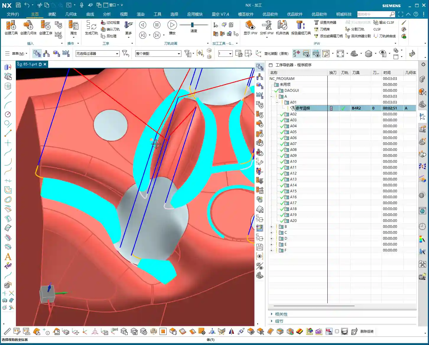
    2. **The Truth About Yellow Toolpath Regions**: When NX calculates toolpaths, it sometimes displays **yellow toolpath regions**. Remember, this is not a program error, but rather NX telling you that this is the tool’s **”machining range” or “intersection area,”** typically used to mark the maximum range that the current tool can cut. You simply need to **”regenerate” the toolpath**, and these yellow regions will disappear, turning into normal blue toolpaths. Don’t hit cancel as soon as you see yellow lines – that’s a misjudgment and a waste of time!
    3. **Matching Strategies to Part Geometry**: Corner cleanup strategies are diverse; there’s no single “best” one, only the most suitable. For parts with many contoured surfaces and high precision requirements, consider “Zigzag-Up” combined with “Alternate from Outside-In”; for deep cavities and bottom corner radii, use “Steep Up”; for narrow sidewalls, use “Follow Part Outline.” You must flexibly choose based on the part’s shape, material characteristics, and precision requirements.
    4. **Balancing Smoothness and Efficiency**: Blindly pursuing smoothness by setting the stepover to the minimum will only extend your machining time indefinitely and increase costs. Learn to combine the “Smoothness” function with reasonable adjustments to “Maximum Stepover.” This way, you can improve efficiency while ensuring quality – that’s the wisdom of an experienced professional!
    5. **Don’t Just Rely on Software Simulation, Watch the Cutting Action!**: The best program still has to run on the machine. Cutting sparks, chip formation, and tool wear – these are the most authentic feedbacks from the shop floor. No matter how beautiful the software simulation, it cannot replace your keen eye and years of accumulated experience!

    Think these things over carefully and master them, and you’ll be well on your way to becoming a true master machinist!

    👤 About the Author:
    The author is a veteran CNC machining professional with 15 years of industry experience, specializing in UG NX programming. This article is an original work representing personal practical insights.

    ⚠️ Copyright Notice: Unauthorized reproduction or distribution without prior communication is strictly prohibited.

  • Siemens NX Fixed Contour Milling Corner Cleanup Operation: Master Wang Teaches You How to Select the

    📝 Key Takeaways: Master Wang guides you through an in-depth exploration of Siemens NX Fixed Contour Milling Corner Cleanup operations, detailing Single Path, Multiple Path, and Reference Tool Corner Cleanup. We’ll critically analyze the “Neighbor Rule” for cutting region selection, teach you to identify and avoid the common yellow line pitfall for new users, ensuring correct toolpath generation and effectively improving machining accuracy and efficiency for complex parts!

    Master Wang’s Lecture: Corner Cleanup Operations – A Quick Review

    Hello everyone, I’m Master Wang. Today, let’s get straight to the point – no beating around the bush. We’re diving into the tough stuff: Corner Cleanup operations. In Siemens NX, this is a true skill, especially for those of us involved in mold making and complex part machining; it’s an everyday task. Since it’s “corner cleanup,” as the name implies, it’s about thoroughly clearing out those “nooks and crannies” that large tools can’t reach or fully machine.

    We’ve previously discussed Fixed Contour Milling, and Corner Cleanup is an important sub-category of Fixed Contour Milling. You need to understand its overall framework first, then learn these specific techniques to truly grasp them.

    The Three Pillars of Corner Cleanup

    In Corner Cleanup operations, there are three main types you need to remember:

    1. Single Path Corner Cleanup
    2. Multiple Path Corner Cleanup
    3. Reference Corner Cleanup: The full name for this one is “Reference Tool Corner Cleanup.” Usually, to save time, I just call it Reference Corner Cleanup, but you should understand its full context.

    These three types, although named differently, essentially serve the same purpose: Corner Cleanup. Moreover, their interfaces and operational logic are quite similar, so we’ll tackle them all at once.

    Corner Cleanup: The Solution for Tight Corners and Accuracy Improvement

    What is Corner Cleanup? Simply put, it’s about cleaning the workpiece’s “base areas”. The residual material left after larger tools have milled, especially in small fillet radii or at the junctions of steep faces, where the tool radius isn’t small enough to reach the entire area, must be addressed by Corner Cleanup.

    The “Savior” for Complex 3D Parts

    In actual production, especially when dealing with complex 3D parts, the importance of Corner Cleanup operations becomes evident. For example, you might first perform a roughing pass with a large tool, then a finishing pass on a Contour Milling operation (meaning those irregular curved surfaces), only to find that some corners are still not clean, or there are areas that were not fully machined. At this point, the Corner Cleanup command comes into play; it can use smaller tools to precisely clean these areas, achieving the required accuracy.

    Especially when we’re making molds or precision products, accuracy requirements are no joke; even an error of ±0.005mm needs to be compensated and resolved. Corner Cleanup is a crucial step in ensuring final dimensional accuracy and surface quality.

    Out of the Three Corner Cleanup Types, Which is the Mainstay?

    Among the three Corner Cleanup methods mentioned earlier, the most commonly used and central one is Reference Tool Corner Cleanup. It has the broadest application scenarios and the most powerful features. Single Path and Multiple Path Corner Cleanup are used less frequently, but each has its specific focus. Today, we’ll start with the simplest: Single Path Corner Cleanup.

    Practical Setup: The Operational Logic of Single Path Corner Cleanup

    All talk and no action is useless. Let’s get hands-on directly. Create a new program group, then insert an operation.

    Coordinate System and Workpiece Selection

    First, establish a Work Coordinate System (WCS). For its position, you can place it arbitrarily at the bottom; this is for practice, but in actual machining, precise positioning is crucial. Then, when inserting an operation, select today’s protagonist – Single Path Corner Cleanup.

    The selection of the Part and Check Geometry goes without saying; this is fundamental. Make sure you select the correct part and fixtures to avoid tool collisions. For this example, let’s select workpiece A and confirm.

    The “Déjà Vu” of the Corner Cleanup Page

    Open the main page for this Corner Cleanup operation. Does it look familiar? Specify Part, Specify Check Geometry, Specify Cut Area, Specify Trim Boundaries… Aren’t these parameters almost identical to what we discussed earlier for Area Milling?

    Exactly! This is a characteristic of Fixed Contour Milling. For these types of operations, most page layouts and parameters are generic. What truly determines whether it’s “Corner Cleanup or Area Milling” is the “Method” option. The method for Corner Cleanup operations is Clean Corner. Therefore, once you’ve learned the general logic of Fixed Contour Milling, learning these specific operations becomes much faster.

    Core Secret: The “Neighbor Rule” for Cutting Region Selection

    Here comes the main event! In Corner Cleanup operations, selecting the cutting region is where new users most often make mistakes, and it’s also the most critical step. Listen closely, this is a practical tip that textbooks don’t teach!

    Essence of Selection: Don’t Just Select It, But Also Its “Neighbors”

    Let’s take an example. Suppose you need to clean a fillet that is formed by the intersection of two faces. How do many new users select it? They directly click the fillet face, or the fillet edge, right? Completely wrong!

    The correct approach is: You must not only select the “base” region you want to clean, but also select its adjacent “neighbor” faces! “Neighbors” refers to the faces that are directly connected to this fillet and form that corner. Selecting all of them ensures that Siemens NX correctly identifies the corner and generates a complete toolpath.

    This logic is the same as what we discussed earlier for Rest Milling. Whenever the concept of a “reference tool” is involved, or the software needs to identify boundaries based on tool dimensions, you must follow this “Neighbor Rule.” Whether it’s selecting faces or selecting lines in Planar Profile Milling, as long as it’s linked to tool characteristics, you must select the adjacent regions as well. Otherwise, the toolpath will at best be incomplete, or at worst, it won’t be calculated at all, or it will be incorrect, which is a complete waste of your time!

    UI “Trick”: The Yellow Line Pitfall – Don’t Fall for It Again!

    After the toolpath is generated, you might see some yellow lines appear on the workpiece. Many new users immediately think, “Oh no, is my toolpath problematic? Why are they all yellow? The toolpath looks off!” They then panic and hit cancel, assuming the command isn’t working. STOP! Don’t panic!

    Yellow Lines: Merely a “Display Issue”

    Listen up, these yellow lines, they are not your toolpath, nor are they an indication of a toolpath error! This is simply a “display issue” or a “display characteristic” of the Siemens NX software. It’s just there to visually indicate that this area is your defined cutting region.

    This has no actual machining significance, and it has absolutely nothing to do with your toolpath. It will not affect your actual cutting. If you don’t believe me, try it: After generating the toolpath, click “Replay”, and you’ll see the yellow lines disappear immediately, right? Or, click “OK”, close the file, reopen it, and check again – the yellow lines will have automatically vanished.

    So, the next time you see these yellow lines, don’t assume the toolpath is wrong; the software is just playing a “little trick” on you. As long as you’ve selected the cutting region correctly and your tool parameters are in order, then confidently proceed, and don’t get misled by this minor detail.

    Toolpath Analysis: The Essence of Single Path Corner Cleanup

    Let’s generate the toolpath now, and then see exactly how it moves.

    One Pass Along the Edge: The Core of Single Path Corner Cleanup

    Look! Doesn’t the tool move tightly along the boundary of our specified region, making only one pass? This is the core characteristic of Single Path Corner Cleanup! It only makes one pass along the deepest part of the corner to remove residual material.

    Therefore, when using Single Path Corner Cleanup, your tool radius becomes particularly important. It should exactly match the target fillet radius you intend to clean. For instance, if you want to clean an R2 corner, you must select an R2 ball end mill, ensuring the tool’s radius matches the workpiece’s fillet radius. This way, the tool can precisely follow the R-angle with a single pass, cleaning off burrs and residual material in one go. If your selected tool radius is incorrect, the result of this single pass will certainly be unsatisfactory, and might even leave new residual material.

    Single Path Corner Cleanup is designed for precisely cleaning individual, well-defined fillet radii or base areas, aiming for the efficiency and accuracy of a single, perfect pass.

    Summary: Pitfall Avoidance Guide

    • Cutting Region Selection is Paramount: Don’t just select the target face; you must also select all “neighbor” faces adjacent to the target face. This is crucial for ensuring correct toolpath generation; otherwise, it’s easy to fail to calculate a toolpath or generate incorrect toolpaths, wasting valuable time.
    • Yellow Lines are Merely a Display Issue, Not a Toolpath Error: When you see yellow lines appear after toolpath generation, don’t panic! It’s merely a visual cue from the software, unrelated to the actual toolpath, and not an error. The yellow lines will disappear after clicking “Replay” or “OK.”
    • Tool Selection Must Match Fillet Radius: For Single Path Corner Cleanup, the selected tool’s corner radius should precisely match the radius of the fillet to be cleaned, ensuring a single, accurate cut and avoiding secondary modifications and accuracy deviations.
    • Generic Logic of Fixed Contour Milling: The Corner Cleanup operation page is similar to other Fixed Contour Milling operations like Area Milling; the core difference lies in the “Method” option. Understanding this commonality will help you master Siemens NX machining programming faster.
    • Practice Makes Perfect: Don’t just read theory; get hands-on, and observe the cutting sparks and actual results. Only then can you truly master these practical tips and wield Siemens NX with expertise.

    “`

    👤 About the Author:
    The author is a veteran CNC machining professional with 15 years of industry experience, specializing in UG NX programming. This article is an original work representing personal practical insights.

    ⚠️ Copyright Notice: Unauthorized reproduction or distribution without prior communication is strictly prohibited.