Tag: Small Mold Machining

  • Siemens NX Roughing Practical Guide for Small Mold Parts: Master Wang’s Hands-on Tutorial on Efficie

    📝 Key Takeaways: ** Master Wang personally explains Siemens NX roughing programming for small mold parts. From part analysis and Work Coordinate System setup to tool selection and practical applications of Cavity Mill and Depth Contour Milling. Key focus areas include toolpath optimization, stock control, minimizing air cuts, and sharing many practical tips you won’t find in textbooks, all aimed at improving machining efficiency and product accuracy. **

    Hello everyone, this is Master Wang. Today, let’s talk about roughing programming for small mold parts. Don’t let the small size of these parts fool you; there are many intricacies involved, especially with complex surfaces. Mishandle them, and you risk scrapped parts or low efficiency. So listen up! Today, I’ll walk you through it and explain all those real-world tips and tricks you won’t find in textbooks!

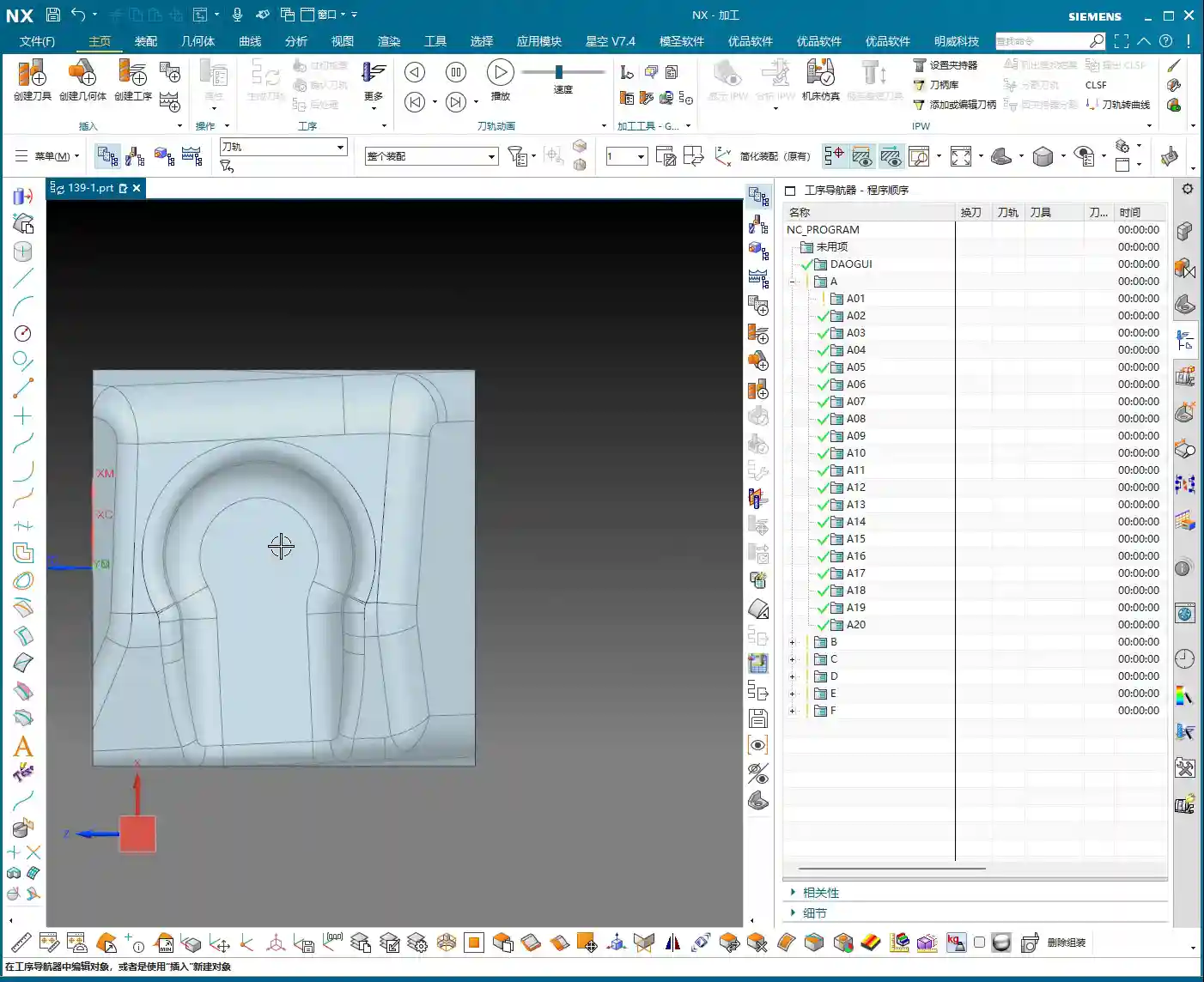
    Step One: Part Analysis and Review – Preparation is Key

    Once you get the job, the first thing is to understand the part thoroughly. This small mold may not look difficult, but there are critical areas.

    Part Characteristics and Challenges

    • Numerous and Complex Surfaces: The part surface has flat areas, but more notably, some “steep” contoured surfaces. In such areas, simply using a standard face milling operation will be disastrous; you’ll either have incomplete material removal or risk tool crashes. For these small and complex surfaces, we must use Depth Contour Milling.
    • Compact Size: The overall part is exceptionally small, which means our tool selection and cutting parameter settings must be more precise. Even a slight deviation can lead to a scrapped part.
    • Internal Radius Requirement: The part’s internal radius is R5. This parameter directly dictates our tool selection for roughing and semi-finishing.

    Fixturing and Work Coordinate System Setup

    The raw blank needs to be secured, that’s common knowledge. But even more important is the Work Coordinate System. For those of us using NX, don’t just stare at the X0Y0Z0 in the software; understand its actual position on the machine!

    • Datum Selection: For this type of raw blank, it’s best to use the bottom surface as the Z-datum. This makes it easier to control the machining Depth of Cut (DOC) and facilitates subsequent finishing passes.
    • Work Coordinate System Verification: Regardless of how you set up your Work Coordinate System, always double-check it. Before starting on the machine, use a probe to verify if the X, Y, and Z values match your programming. Don’t underestimate this step; countless accidents are caused by misaligned Work Coordinate Systems! I’ve seen it too many times – just to save a few minutes, parts worth tens or even hundreds of thousands were scrapped.

    Step Two: Tool Selection and Roughing Strategies – The Tool Arsenal and Strategic Planning

    Your tools are your weapons; choose them correctly, and you’ll achieve twice the result with half the effort. Choose them poorly, and you might not even save the tool itself.

    Tool Configuration

    • Roughing Tool: Given the R5 internal radius, we can select a Φ12R3 (12mm diameter, 3mm corner radius) flat end mill with a corner radius. This tool can better remove most of the stock, while also addressing the radius areas, leaving appropriate stock for subsequent semi-finishing.
    • Semi-Finishing/Finishing Tools: For areas with an internal R5, a Φ8 (8mm diameter) ball nose end mill can be considered for semi-finishing. This ensures the quality and efficiency of the subsequent finishing pass. For the steeper external areas, the Φ12R3 can be used for roughing.

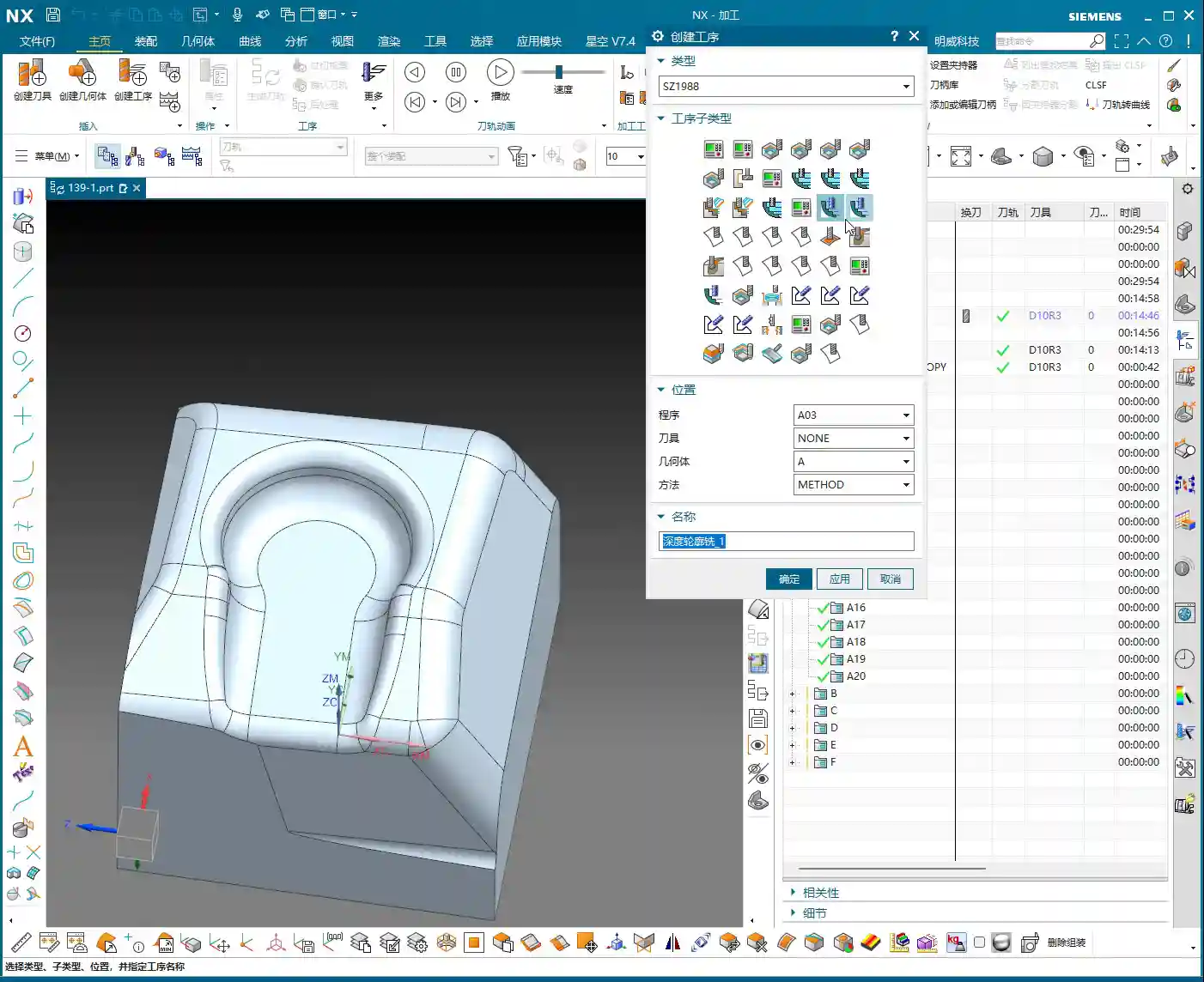
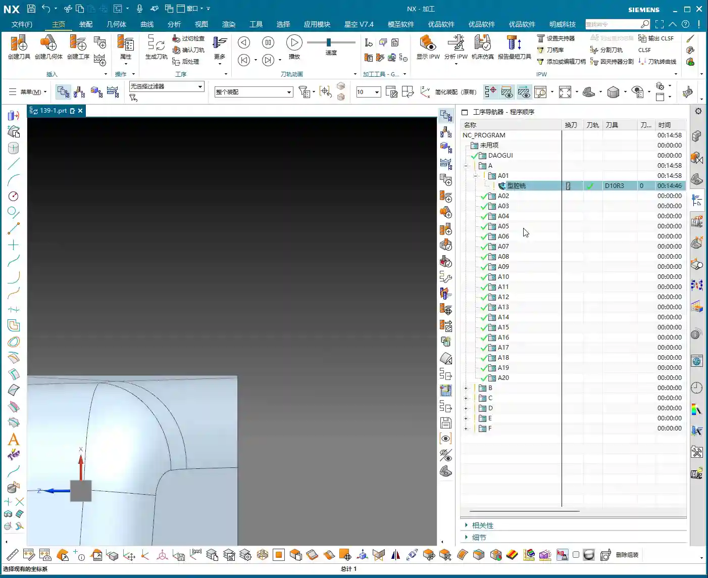
    Roughing Toolpath Programming (Siemens NX Cavity Mill)

    NX’s “Cavity Mill” function is a powerful tool for roughing, but knowing how to use it is key.

    • Operation Creation:

      1. Create a new ‘Work Area’ and define the machining boundary.
      2. Set the safety plane: For example, designate Z=100mm as the safety plane to ensure the tool does not collide with the workpiece or fixture in non-cutting areas.
      3. Select the Cavity Mill operation.
      4. Sequentially select the Part Geometry and Blank Geometry.
      5. Select the tool: Φ12R3.

    • Cutting Parameter Optimization:

      • Depth of Cut (DOC): Initially set to 0.5mm. This can be adjusted based on material hardness, tool life, and machine power.
      • Cutting Pattern: Don’t just use the default ‘Follow Boundary’ pattern right away. For roughing small molds, the ‘Follow Periphery’ pattern is often more stable, generates a more consistent toolpath, and reduces unnecessary retracts and air cuts.
      • Engagement Method: Software simulation looks good, but the actual cutting sparks are what truly matter. Initial straight plunges or helical plunges can lead to aggressive Depth of Cut (DOC). Try using ‘Arc Plunge’ with a parameter set to 5mm; this allows the tool to enter the material more smoothly and avoids shock.

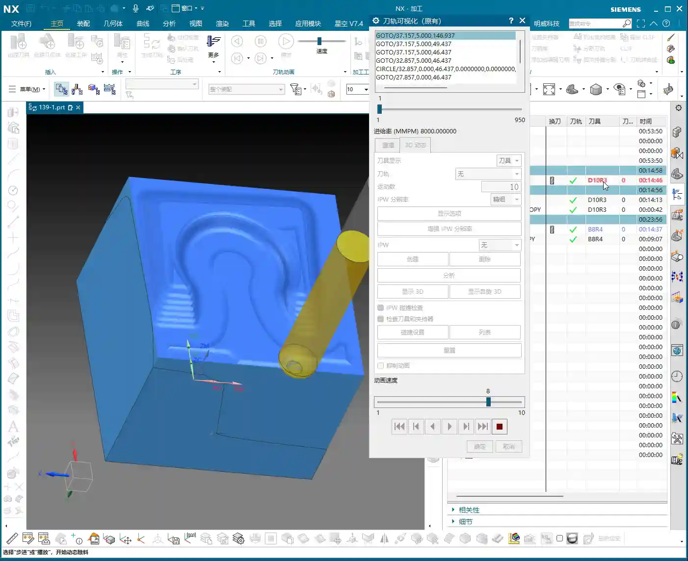
    Step Three: Stock Control and Finishing Strategies – Striving for Perfection

    Roughing is not the ultimate goal; it’s about setting the stage for finishing. How much stock to leave and where to leave it – these are crucial considerations.

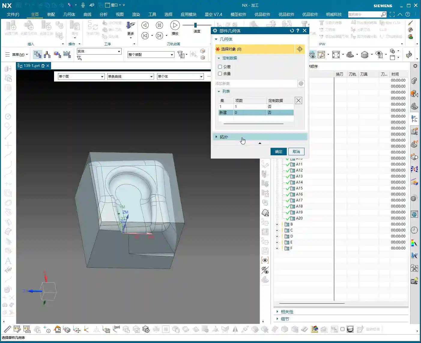
    Roughing Stock Adjustment

    Analyze the remaining stock using IPW (In-Process Workpiece). Initially, the system’s default stock might be 0.3mm. However, for small molds, too much stock puts excessive pressure on semi-finishing, while too little risks insufficient material for the final finish. Typically, adjusting it to 0.2mm is sufficient. Regenerate the toolpath to ensure uniform stock.

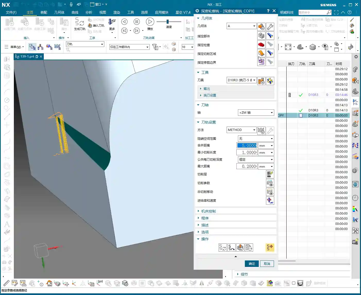
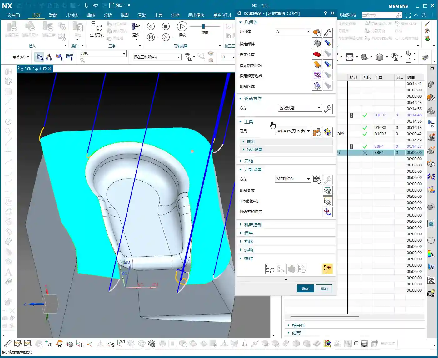
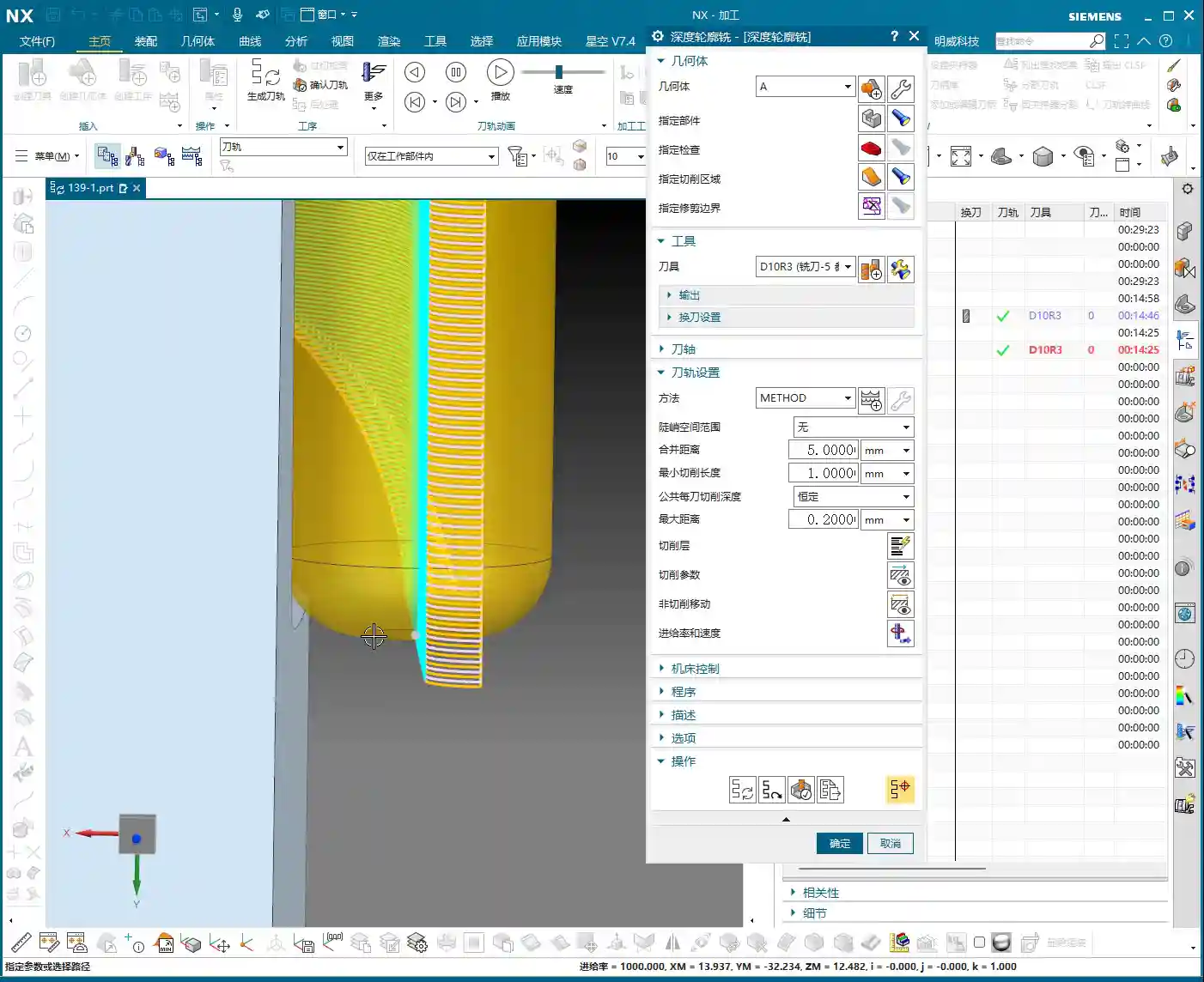
    Surface Finishing: Depth Contour Milling

    For those “steep” contoured surfaces and complex areas, conventional planar milling won’t cut it. This is where Depth Contour Milling comes in.

    • Operation Creation:

      1. Right-click ‘Insert Operation’ and select Depth Contour Milling.
      2. Select the surfaces to be machined: Choose carefully, especially the blue areas (which typically represent curved surfaces in Siemens NX), as these require precise treatment. Green areas are typically flat surfaces.
      3. Tool: Continue using the Φ12R3 for semi-finishing (or switch to a Φ8 ball nose end mill for finishing, depending on actual requirements).
      4. Depth of Cut (DOC): 0.2mm.
      5. Cutting Pattern: 0: This means this pass will be a finishing pass, or at least a semi-finishing pass close to a finishing pass.
      6. Toolpath Extension: The toolpath can be extended appropriately to ensure the tool fully exits the cutting area, preventing tool marks on the part edges.

    Step Four: Toolpath Optimization and Practical Verification – Details Determine Success

    Programming is done, but that doesn’t mean everything is finished. Toolpath optimization and verification are the final checkpoints to ensure machining quality and efficiency.

    Minimizing Air Cuts and Retracts

    In Siemens NX, you’ll often see the tool frequently retracting and plunging – these are “air cuts” or “jumps.” This significantly reduces machining efficiency and increases machine wear.

    • Adjusting Engagement and Retract Parameters: Carefully check the engagement and retract settings within ‘Non-Cutting Moves’. For continuous machining areas, you can set the Clearance or Retract height to 0, allowing the tool to move rapidly within the plane and reduce unnecessary retracts. If necessary, you can set a small Extend distance (e.g., 3mm) to avoid retracting in the middle of the workpiece.
    • Observe the Toolpath: When simulating the toolpath, observe the tool’s motion trajectory carefully, just as you would in front of the machine. Any unreasonable movements or redundant actions must be adjusted promptly.

    Verify Machining Results

    Achieving accurate machining is a fundamental requirement. Use IPW analysis again to ensure all surfaces have been machined to the preset stock or to a finishing pass. Pay special attention to corners and grooves, checking for any cases of “Corner Cleanup” (rest milling) not being fully achieved or “overcutting.” These are the most common pitfalls in machining.

    Summary: Pitfall Avoidance Guide

    • The Work Coordinate System is paramount: Align it! Verify it! Re-verify it! Don’t ruin an entire part to save a few minutes.
    • For small parts, precise tool selection is crucial: The radius dictates the tool. A Φ8 ball nose end mill can finish an R5 corner. The roughing corner radius end mill should also consider Corner Cleanup.
    • Choose the right cutting pattern: For surface roughing, ‘Follow Periphery’ is often better than ‘Follow Boundary’; it’s more stable and reduces air cuts.
    • The engagement method is key: ‘Arc Plunge’ protects the tool more and is smoother than a straight plunge.
    • Stock control is an art: For small mold roughing, 0.2mm of stock is sufficient, which lightens the load for subsequent finishing.
    • For complex surfaces, use ‘Depth Contour Milling’: This is Siemens NX’s go-to for complex surfaces, so master it.
    • Toolpath optimization reduces air cuts: Lowering retract heights can significantly improve machining efficiency; saving time means saving costs.
    • Simulation ≠ Real-world Machining: No matter how perfect the software simulation, the final result depends on what the machine actually produces. Observe, analyze, and adjust frequently.

    Alright, that concludes today’s hardcore practical session on small mold roughing. Next time, we’ll continue discussing how to finish other areas.

    Thank you for watching, and see you next time!

    👤 About the Author:
    The author is a veteran CNC machining professional with 15 years of industry experience, specializing in UG NX programming. This article is an original work representing personal practical insights.

    ⚠️ Copyright Notice: Unauthorized reproduction or distribution without prior communication is strictly prohibited.

  • Siemens NX Full Sequence Programming for Small Mold Parts: Master Wang’s 15 Years of Practical Exper

    📝 Key Takeaways: Master Wang shares practical insights on full sequence Siemens NX programming for small mold parts: covering everything from rest milling to finishing passes. The focus is on effectively addressing corner remnants, optimizing toolpaths with Siemens NX, and boosting machining efficiency. He emphasizes the practical application of surface selection, Depth of Cut control, and helical entry to bridge the gap between theory and real-world machining.

    I. Rest Milling: Don’t Let Small Remnants Spoil Your Finish Pass

    Listen up, apprentices. Today, let’s talk about full sequence programming for small mold parts—it’s not just about clicking a mouse. Especially after roughing and before moving to finishing, there’s a critical step: **rest material cleanup**. It might seem trivial, but it’s key. As I’ve said before, once the program runs, a dynamic simulation often reveals those tiny remnants in certain areas, particularly in **corners and deep slots**.

    1. Initial Rest Material Handling and Simulation Verification

    After the last program ran, you might think it’s good enough. But run a simulation, and see? In this area (pointing to a specific region on the model), isn’t there still a bit of **rest material**? Don’t underestimate that “little bit”; it’s a **hidden danger** for your subsequent finishing passes. So, we need to add another operation specifically to clear it out. Remember, NX dynamic simulation isn’t just for show; use it extensively, examine it closely, especially when simulating cutting sparks and material buildup – that’s where the real skill lies.

    We can copy the previous operation and then, for this specific rest material area, select only that small fillet for cleanup. For the Depth of Cut, let it go a bit **deeper** and extend the toolpath a bit further. Even if it seems “excessive,” ensuring the material is fully machined is always better than under-machining. It’s like in life, always leave a little leeway.

    2. Depth Control and Surface Selection Techniques

    A common mistake here is when the program doesn’t generate. Why? Nine times out of ten, it’s because the surfaces weren’t selected correctly or the cutting parameters are unreasonable. In NX, after you set the machining area, if the toolpath doesn’t generate, first check your selected machining surfaces and boundaries. Sometimes, missing just one small surface can cause the entire program to “strike.”

    Also, learn to control your cut layers. For example, if we want to start machining from a specific surface, NX has the “Starting Cut Level” option. Directly specify which surface to start from and move downwards, rather than from the highest point of the model. This effectively avoids air cutting and allows for more precise control over the Depth of Cut.

    I just demonstrated and noticed the toolpath was still a tad short. What do you do then? You don’t change the tool; instead, adjust the “Cut Layer” **”Extension Amount”** to extend it downwards by 0.5 mm. That’s enough. Don’t underestimate that 0.5 mm; it’s the secret weapon for ensuring no rest material is left in the corners.

    II. Machining Strategies for Corner Regions: Detailed Processing

    Next, let’s focus on those corners prone to accumulating “dirt.” Small molds are all about precision and surface quality; if the corners aren’t clean, the whole part is useless.

    1. Selecting the Correct Machining Area and Tool

    We insert a “Rest Machining” or “Area Milling” operation. Select the part, then the cutting region. In this area, I generally recommend selecting all relevant surfaces to ensure complete coverage. However, for certain special areas, like narrow slots in deep cavities, you can initially skip them and address them later with a finer tool or specialized toolpath.

    Regarding tool selection, as I said earlier, we’re using a D8 ball end mill. For finishing small molds, ball end mills are your workhorse. When choosing a tool, don’t just look at the diameter; also consider the tool’s flute length, shank diameter, and tool holder length to ensure no interference and smooth machining to the deepest points. Especially when performing collision detection in NX, that’s not something to take lightly; one collision could scrap a machine worth hundreds of thousands.

    2. The Art of Climb Milling Direction and Toolpath Strategy

    In NX, the cutting direction also matters. For instance, in this area, letting the tool run with climb milling yields better surface quality and longer tool life. Especially when machining challenging materials like titanium alloys or superalloys, climb milling effectively reduces built-up edge and enhances cutting stability. This requires adjusting the “Machining Strategy” within the “Cutting Parameters” in NX.

    Furthermore, the toolpath strategy is crucial. For mold cavities, especially those with slight tapers, Spiral Inward plunge is often more efficient than parallel passes, and the toolpath is smoother. It ensures the tool is continuously cutting, reduces air moves, and avoids sudden tool loading in corners, extending tool life. You can select “Spiral” or “Spiral Inward” path types in “Cutting Method”; try them out to see which works best.

    III. Tool Selection and Entry Methods: Optimizing Machining Efficiency

    The tool is the “tooth” of CNC machining; if you choose it incorrectly or use it poorly, even the best machine is useless.

    1. Flexible Switching Between Large and Small Tools

    Earlier, we used a D8 ball end mill for cleanup, but sometimes you’ll find an R3 tool might be too large, unable to fully clear certain areas, or simply inefficient. At this point, you need to consider a **”tool change”** strategy.

    For instance, during the roughing stage, you can boldly use a larger tool, like an R1 tool (an R1 tool is a ball end mill or bull nose end mill with a 1mm corner radius). This boosts efficiency. However, for finishing small molds, especially intricate features, you’ll need to switch to a smaller tool, or even a small carbide end mill. Remember, matching tool size with feature geometry is the prerequisite for achieving high precision.

    Of course, tool changes aren’t random. You need to consider tool change time costs and tool magazine capacity. When programming in NX, you can plan your tool sequence in advance to minimize unnecessary tool changes.

    2. Layered Machining and Safe Tool Entry

    For areas with significant depth or complex cavity shapes, “layered machining” is often the most effective approach. Cutting down layer by layer, from top to bottom, can significantly reduce tool load and prevent chipping. This can be achieved in NX by setting the “Depth of Cut” and “Depth per Cut” (Stepdown).

    Tool entry methods are also paramount. Besides the helical entry mentioned earlier, NX offers various entry methods, such as “Ramp entry” and “Plunge entry”. Choosing the right entry method effectively protects the tool, reduces impact, and extends tool life. Don’t underestimate these details; this is where you learn the “machine’s temperament” that isn’t found in textbooks.

    Finally, make extensive use of the “Clearance” function. NX’s “Non-Cutting Moves” has many options; properly setting retract height and approach/retract safety distances ensures the tool doesn’t collide with the workpiece or fixturing during non-cutting movements – this is the baseline for safe production.

    Summary: Pitfall Avoidance Guide

    • Dynamic Simulation is essential: Don’t rely solely on experience and guesswork; use NX’s simulation functions repeatedly, paying close attention to rest material and collisions.
    • Precision in Surface Selection: When selecting machining areas, even a small missed surface can lead to program errors or incomplete machining. It’s better to over-select than to under-select.
    • Cut Layers and Extension: Flexibly use “Starting Cut Level” and “Extension Amount” to precisely control the Depth of Cut, especially for corner cleanup.
    • Experiment with Toolpath Strategies: Helical entry, layered machining, and others – choose the most suitable one based on part characteristics; don’t use a one-size-fits-all approach.
    • Tool Matching Principle: Small features require small tools, deep cavities require long tools. Roughing uses large tools, finishing uses small tools. It’s not about the most expensive, but the most suitable.
    • Pay Attention to Detail Parameters: Climb milling and conventional milling each have their applicable scenarios; don’t mix them up, as it affects surface quality and tool life.

    Alright, that’s it for today’s practical takeaways. Practice more, ponder more; NX programming is a skill that comes with practice, but within that mastery, you need these real-world insights. We’ll pick up next time. If you have any questions, feel free to ask anytime.

    👤 About the Author:
    The author is a veteran CNC machining professional with 15 years of industry experience, specializing in UG NX programming. This article is an original work representing personal practical insights.

    ⚠️ Copyright Notice: Unauthorized reproduction or distribution without prior communication is strictly prohibited.