Tag: UG Programming

  • UG (NX) Hands-on Programming for Graphite Complex Geometry Parts (Front Face First Operation): Maste

    📝 Key Takeaways: Master Wang provides a hands-on explanation of first-operation programming for graphite complex geometry parts (front face) in UG. He shares invaluable, real-world UG (NX) tips and tricks not found in textbooks, covering tool selection, parameter tuning, collision prevention, cutting direction determination, and blank definition with WCS setup. He emphasizes small Depth of Cut (DOC) and multiple passes, as well as the optimization strategy of using previous operation results as the blank for subsequent operations, all to enhance efficiency and avoid pitfalls in precision machining.

    Opening Remarks: UG Programming, Practical Experience is Paramount

    Hello everyone, I’m Master Wang! I’ve been in the machining industry for fifteen years, having worked with everything from turning, milling, planing, grinding, to EDM. Now I mainly focus on UG (NX) programming. Don’t let the fancy software fool you; ultimately, it all comes down to the machine. Today, let’s talk about front face first operation programming for graphite complex geometry parts. Listen up, this job might look simple, but there are many intricate details. I’m going to share some practical tips you won’t find in textbooks.

    Step One: Tool Selection and Parameter Tuning – Don’t Use Blindly!

    The Tool’s “ID Card”: Rebuilding and Naming

    Since it’s a graphite part, the material is brittle, generating a lot of dust during machining, and causing rapid tool wear. We need to select tools based on the actual situation. As mentioned in the audio, an 8mm ball end mill is to be used, but its parameters might be incorrect, so it must be rebuilt first. Why? Because the previous parameters might not have been set for graphite. After rebuilding, give it a clear name, such as “8mm_R5_Graphite_Specific_Ball_End_Mill“. Consistent naming helps the next shift’s machinist understand the tool’s purpose, preventing misuse.

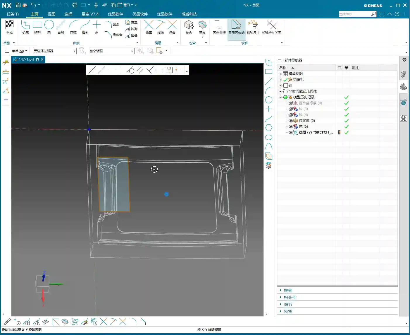
    Tool Dimensions: A Millimeter’s Difference, A Collision’s Consequence

    Listen up, here’s a critical detail. Initially, it might have been set to 10mm, but in practice, to prevent interference with the part, we temporarily changed it to 6mm. Master Wang’s exact words were: “Look, if it’s 6 [mm], and you start machining upwards from this face, if you were to start machining upwards from the back side at this position, wouldn’t we already collide at this point? Right? So we absolutely must start machining inwards from this face.”

    This is a classic collision warning! Don’t just rely on software simulations; they can sometimes be misleading. For real jobs, you need to mentally walk through the toolpath. Especially with complex geometry parts, the structure is intricate, and even a slight miscalculation in tool dimensions can lead to minor issues like tool chipping, or major issues like a machine crash. So, when adjusting parameters in UG (NX), such as tool diameter, tool length, and holder length, always proceed with extreme caution and verify thoroughly.

    Step Two: Process Path and Cutting Strategy – Balancing Efficiency and Quality

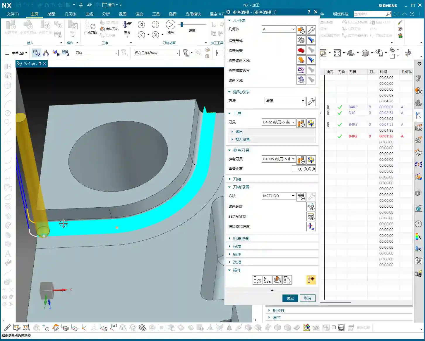
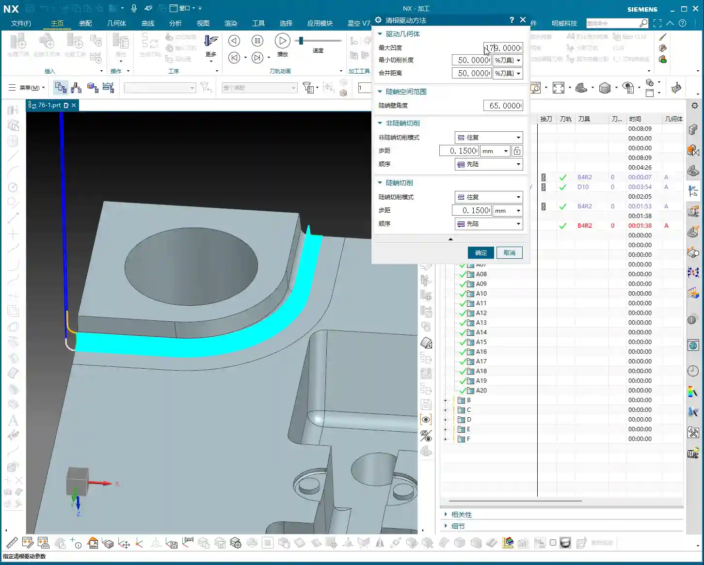
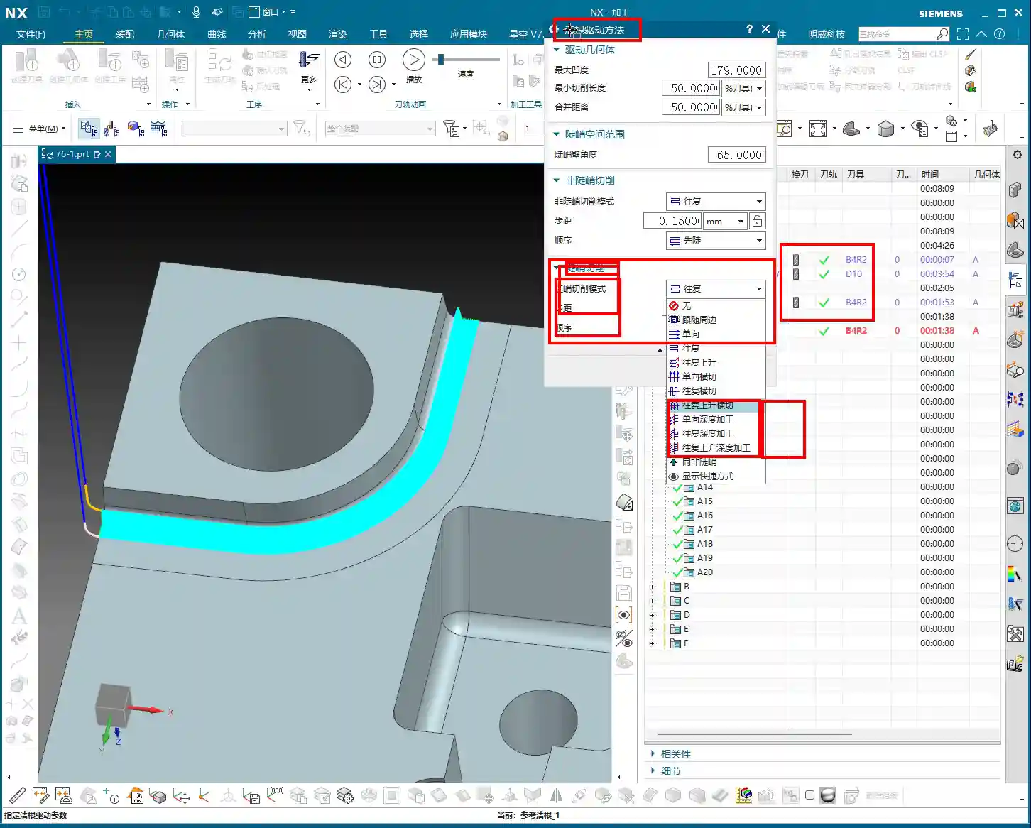
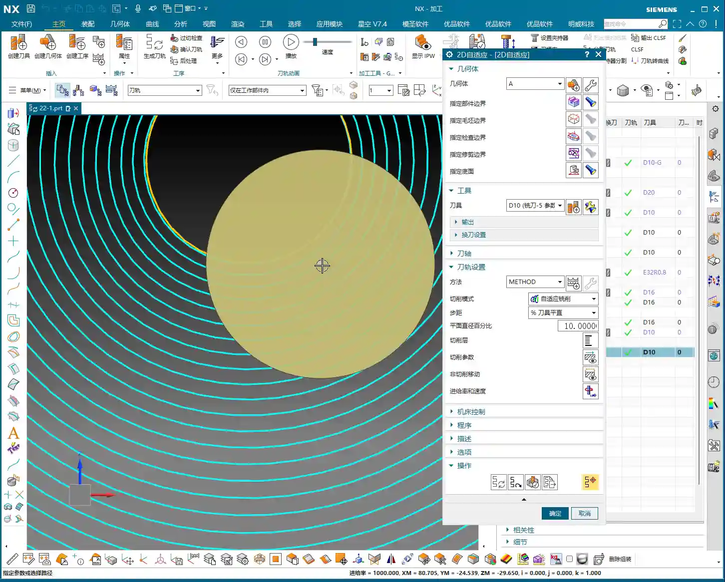
    Precise Selection of Drive Geometry

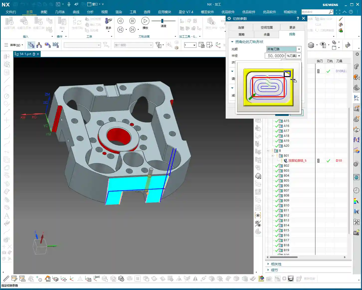
    Many of those flashy options in the software are often unnecessary. We’ll go directly into the “wrench” tool and simply select the correct Drive Geometry. This is like assigning a patrol route to the tool; once the route is clearly defined, it can get to work systematically.

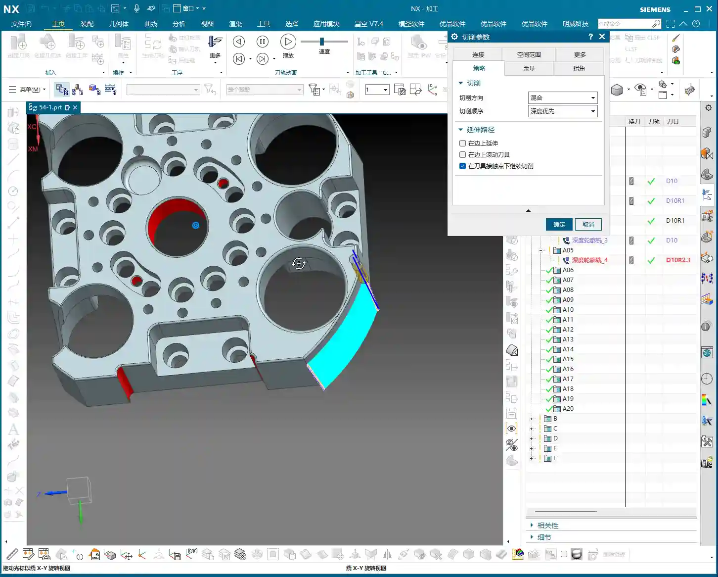
    Cutting Direction: Climb Milling or Conventional Milling?

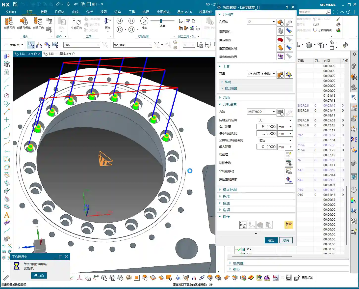
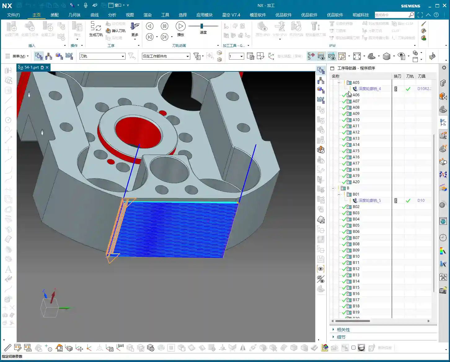
    This is an age-old question, but for special materials like graphite, it’s particularly crucial. Master Wang emphasizes the need to check if the cutting direction is correct, or if it’s reversed. In UG (NX) programming, the default is usually Climb Milling, which is what we use most frequently. The advantage of climb milling is stable cutting, even tool forces, less tool wear, and good surface finish. If the direction is reversed, resulting in conventional milling, the graphite part will be prone to chipping and burrs, and tool life will be significantly reduced. Therefore, after generating the toolpath, the first thing to do is drag the toolpath with the mouse and carefully check the direction – don’t get lazy!

    Entry Depth and Toolpath Extension: Details Determine Success

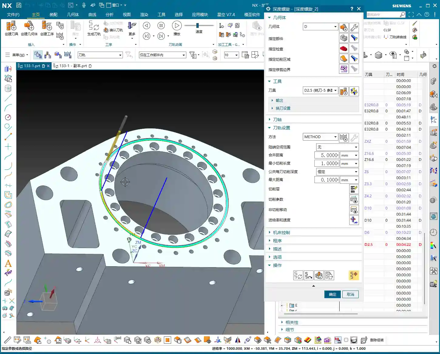
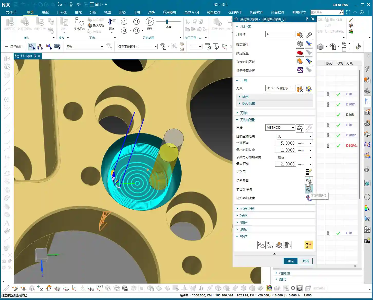
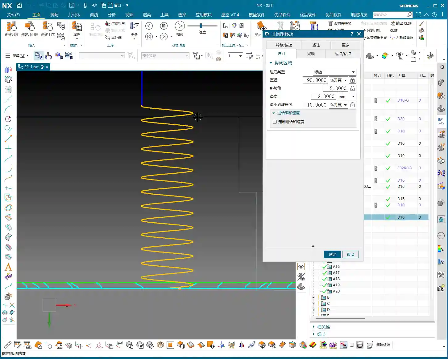
    This program is used to machine a “feature cutout” on the part, which is a recess or specific feature. Master Wang mentioned: “It’s not good for the tool to plunge directly at this edge; it needs to extend a bit.” This is practical experience! A tool plunging perpendicularly directly into the material can cause impact and chipping. We want the tool to smoothly enter the cut from the outside of the part. In UG (NX), this can be achieved by setting the Extend Distance. For example, by extending the toolpath outwards by -2mm and adjusting the depth to 102mm (specific values depend on the actual situation), the tool can have a buffer outside the material before entering the cut. This small extension effectively protects the tool and improves surface quality.

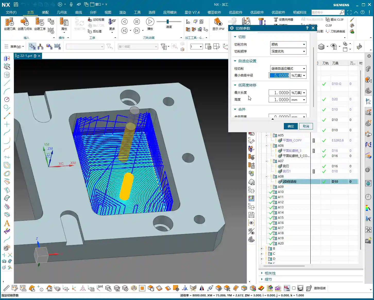
    As for the Depth of Cut (DOC) (how much material to remove per pass), Master Wang’s recommendation is 0.2mm Depth of Cut (DOC) per pass. Although graphite material is soft, it has poor toughness, and too large a Depth of Cut (DOC) can easily cause chipping. This 0.2mm empirical value is derived from countless trials and errors, balancing both efficiency and part integrity.

    Step Three: Blank and Fixturing: Precise Positioning for Seamless Flip-over Machining

    First Operation Blank Definition and Flip-over Machining Strategy

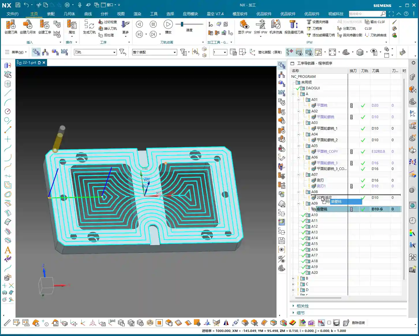
    After the front face first operation is complete, it’s typically followed by flip-over machining. At this point, the part machined in the previous operation becomes the “blank” for the new process. Master Wang’s approach is very clear: “Once we’re done with this side, we’ll take out the fixture, place the part on it, then rotate the part 180 degrees, and proceed with the backside machining.”

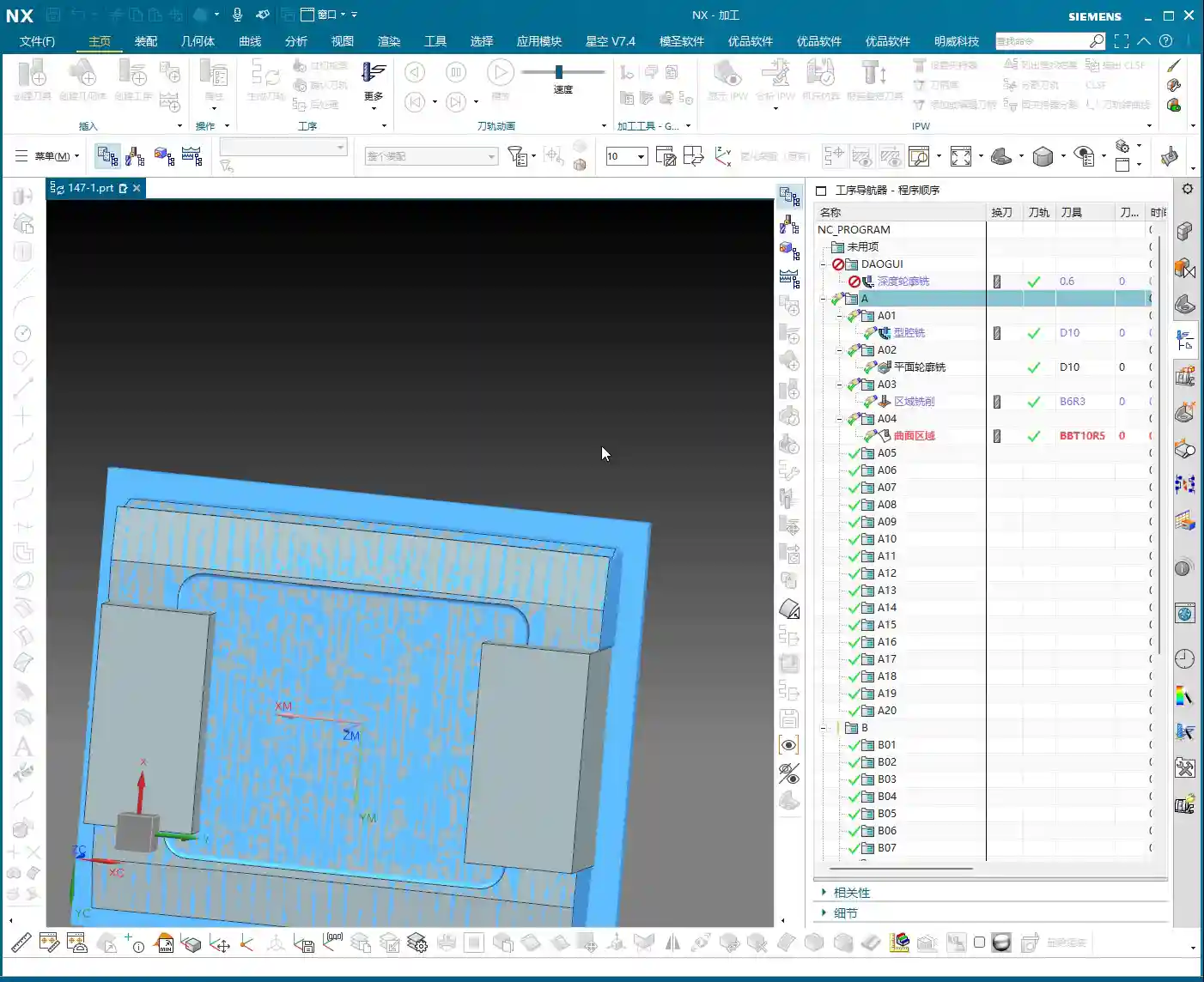
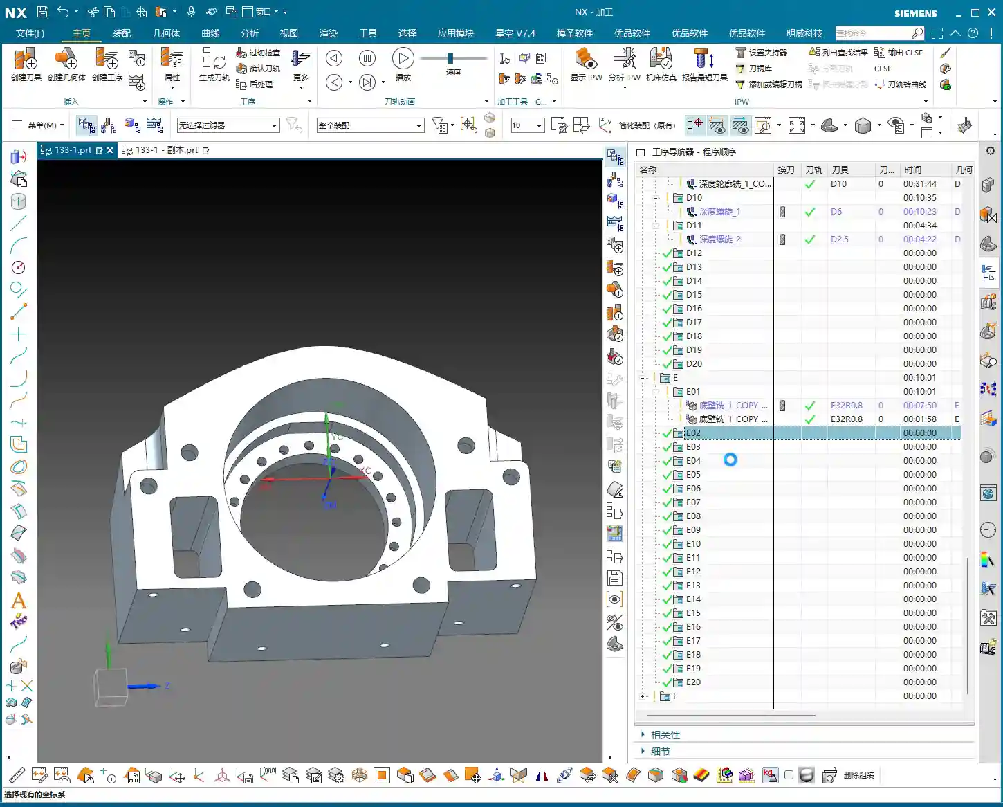
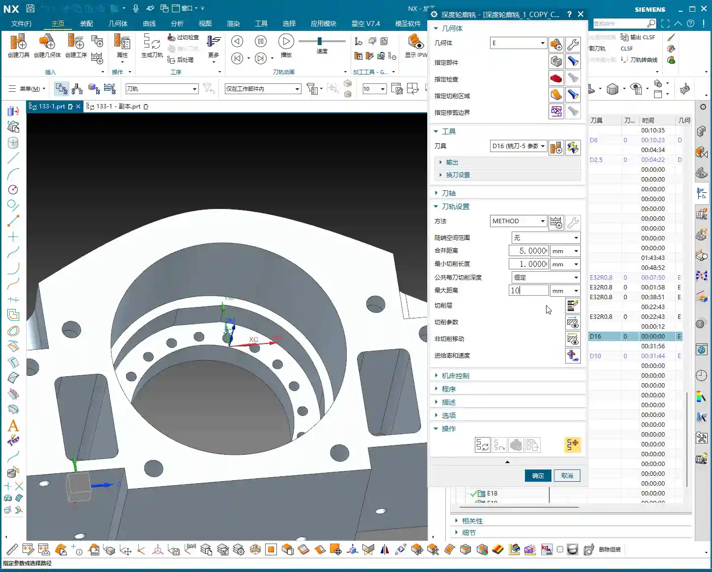
    In UG (NX), this means you need to redefine the Work Coordinate System (WCS) and the blank. It’s not just a simple flip of the model; you must use the solid model resulting from the first operation as the blank for the second operation. This ensures accuracy in subsequent toolpath calculations, preventing air cuts or overcutting. Master Wang also mentioned in the audio that it’s important to “create a block geometry” to define the machining boundary, which is a very practical strategy for precisely controlling the toolpath range, especially for complex geometry parts.

    WCS Setup: Datum Consistency is Critical

    Setting up the WCS, or Work Coordinate System, is fundamental to machining accuracy. When setting it up, Master Wang emphasized selecting the Work Coordinate System, then the plane, and then specifying an offset (e.g., 100). This 100mm offset might be to raise the machining face to an absolute height convenient for operation and measurement, or to accommodate a specific fixture height. Remember, no matter how you set it up, it must maintain high consistency with the actual tool offsetting and fixturing datums on the machine tool; otherwise, all efforts are moot.

    Blank Replacement and Mirroring: Handling Complex Structures

    During UG (NX) operations, you might encounter minor issues, such as “Why is the model red?” or “Why did mirroring merge?” as mentioned in the audio. Master Wang’s approach is to right-click and replace, or to reprocess via planar mirroring. This teaches us not to be intimidated by superficial software phenomena; most of the time, there are flexible solutions.

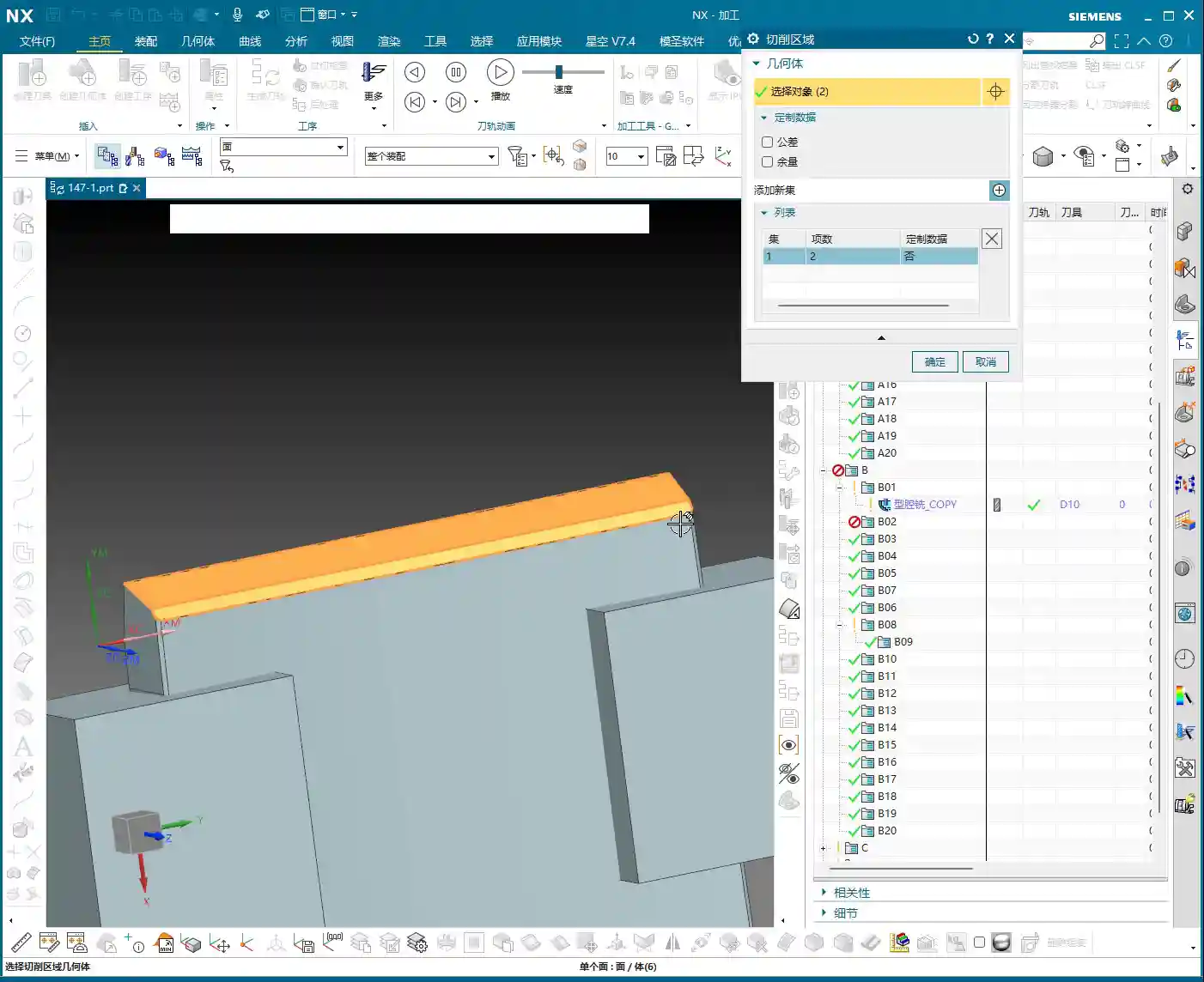
    Especially when dealing with complex geometry parts, simulating the first operation to generate the machined blank, and then using this as the blank for the second operation, is a core step to ensure accuracy and efficiency in multi-operation machining. This approach not only provides a visual representation of the first operation’s outcome but also allows for more precise toolpath calculations in the second operation, avoiding already machined areas, reducing air cuts, and improving overall efficiency. This is the principle of “using the blank from the first operation as the input for the second operation.”

    Summary: Pitfall Avoidance Guide

    1. Tool Parameters: Err on the Side of Smaller: Especially for diameter and length, when setting them in UG (NX), it’s better to be conservative and fine-tune during actual machining. Blindly pursuing larger or longer tools is simply setting a trap for a collision.
    2. Always Check Cutting Direction: After generating each toolpath, take a few seconds to check if it’s climb milling or conventional milling. For graphite machining, climb milling is the preferred choice, as it significantly improves surface quality and extends tool life.
    3. Toolpath Entry Must Be Gradual: When the tool plunges, avoid direct perpendicular entry into the material. Use UG (NX)’s extension function to allow the tool to enter smoothly from outside the part, reducing impact.
    4. Strictly Control Depth of Cut (DOC) per Pass: For brittle materials like graphite, small Depth of Cut (DOC) and multiple passes are paramount. Master Wang’s recommended 0.2mm Depth of Cut (DOC) per pass is knowledge gained from hard-won experience.
    5. WCS Must Be Consistent with Machine Datums: The coordinate system settings in UG (NX) must match the tool offsetting and fixturing datums on the machine tool. This is an ironclad rule for ensuring dimensional accuracy.
    6. Linkage of Blanks Across Multiple Operations: For multi-sided parts, always use the machining results from the previous operation as the blank for the subsequent one. This maximizes the avoidance of air cuts and overcutting, and is key to optimizing toolpaths and enhancing efficiency.
    7. Don’t Blindly Trust Software; Observe Cutting Conditions: Software simulation is just a reference. During actual machining, observe the cutting conditions, the sound of the tool, and any vibrations. This on-site feedback provides the most authentic signals!

    In our line of work, theory is important, but practical experience is even more so. UG (NX), no matter how powerful, is just a tool. How much power that tool can unleash in your hands depends on your mind and skill! That’s all for today; feel free to ask any questions, Master Wang here will tell you everything I know!

    As a senior industrial product marketing expert, I also want to add: To all my colleagues, if you have high-precision graphite complex geometry part machining needs, or if you want to improve UG (NX) programming efficiency and optimize machining processes, our team has extensive practical experience and solutions. Feel free to contact me anytime, and let’s work together to bring excellent products to the global market!


    👤 About the Author:
    The author is a veteran CNC machining professional with 15 years of industry experience, specializing in UG NX programming. This article is an original work representing personal practical insights.

    ⚠️ Copyright Notice: Unauthorized reproduction or distribution without prior communication is strictly prohibited.

  • UG (NX) Part Finishing: Master Wang’s Practical Guide to Avoiding Pitfalls, Enhancing Precision and

    📝 Key Takeaways:

    Practical Finishing in UG (NX)

    Hello everyone, I’m Master Wang. Today, let’s continue our discussion on the intricacies of part finishing…

    [VIDEO_HERE]

    Hello everyone, I’m Master Wang. Today, let’s continue our discussion on the intricacies of part finishing. This job might look simple, but to do it right, you need practical experience. Listen up, I’m going to share all my accumulated wisdom.

    I. Preparation for Finishing: Workpiece and Tool Selection

    Finishing Strategy for Radii and Slots

    For the parts we’re working on, some areas require a finishing pass. Take the R2.5 fillet, for example. Many might immediately reach for a small tool, but that’s often unnecessary. To balance efficiency and tool life, I typically choose a D10 end mill to tackle it. Don’t just rely on the tool catalog; consider the actual situation. Good tool rigidity is essential for ensuring surface finish.

    Additionally, for some deeper slots or bores, such as the R9 bore/slot, a D6 or D8 tool can also be used. Provided there’s no interference, try to use a slightly larger tool for better rigidity and higher cutting stability. This is crucial for both machining precision and surface finish.

    II. UG (NX) Machining Operations and Toolpath Optimization

    Finishing Parameter Settings

    In UG, the core of any finishing program is to control the feed rate and remaining stock. Put aside your roughing programs for now. What we need to do is completely remove all remaining stock.

    • Finishing Depth: For finishing passes, the Depth of Cut (DOC) for a single pass is generally controlled at 0.5 mm. This ensures both surface finish and minimizes machining time. For harder materials, such as titanium alloys or high-temperature nickel-based alloys, the stepover needs to be even smaller, and specialized coated tools might even be required.
    • Stock Control: For all finishing operations, both part stock and blank stock must be set to 0. This step is critical; otherwise, it’s not truly a “finishing” operation. Leave even a few thousandths of a millimeter of stock, and you’ll be dealing with rework.

    Toolpath Adjustment for Complex Areas

    For fillets in corners and edges, if you follow the default path directly, UG might “gouge” the material in the corner or fail to reach it completely. This is when you need to use the trim function to precisely control the toolpath. By adjusting the trim boundaries, you can make the toolpath better conform to the part contour, especially for internal fillets in grooves, preventing overcutting.

    Furthermore, when selecting machining faces, remember this: you don’t always need to select the entire part. Especially in certain situations, for example, when the tool diameter precisely matches the feature size to be machined (e.g., a 2.5mm tool machining an R2.5 fillet), UG might be unable to generate a toolpath. In such cases, you only need to select one side or a single face, and the program will generate smoothly. This is a little trick they don’t teach you in books.

    Application of “Constant Z Spiral Machining”

    For holes or cavities with moderate depth and a taper, if the “constant Z spiral” toolpath isn’t ideal, you can try “Constant Z Spiral Machining”. This method allows the tool to descend smoothly from top to bottom in a helical motion, resulting in more uniform cutting, reduced tool wear, and improved surface quality. However, remember that if the machining surface is complex, or if there are special requirements, you might need to manually adjust the connection method, or even change to a “follow” toolpath to ensure more logical tool movement.

    III. Tolerances and Tool Compensation: Key to Precision Control

    When and How to Apply Tool Compensation

    Many times, design drawings specify high-precision tolerances for certain dimensions, especially for bores and slots, such as ±0.005 mm (approx. ±0.0002 inch) or even tighter. In such cases, relying solely on the program won’t achieve it; the machine’s inherent precision errors and tool wear will affect the final dimensions. What to do? Apply tool compensation!

    Applying tool compensation is simple:

    1. In UG’s “Machine Control”, find “Tool Compensation Parameters”.
    2. Select to enable tool compensation; the direction is typically “Left” (G41).
    3. Here’s the key point: enable tool compensation “before each entry move” and “after each retract move”.
    4. Set the compensation number to D01 (or D02, D03, depending on your machine and tool numbering).

    Note: Programs with tool compensation must be generated and machined separately! Do not mix them with other programs. This is because tool compensation is applied at the machine controller, not by altering the toolpath within the UG program itself. You must first machine the part, then measure it, and based on the measurement results, adjust the corresponding compensation value for D01 in the machine’s CNC system to achieve ±0.005 mm (approx. ±0.0002 inch) level precision.

    IV. Program Generation and Simulation Verification

    Generation and Inspection

    After every parameter change, remember to regenerate the toolpath. UG’s calculation speed depends on the complexity of your part and your computer’s specifications. Waiting a minute or two is normal, don’t rush it. Once the toolpath is generated, don’t just send it to the machine! You must carefully inspect the toolpath, especially the entry, retract, and lift moves, and check for any overcutting phenomena.

    I’ll teach you a simple method to identify overcutting: observe the cutting sparks in the UG simulation. If you see unusually large sparks in a particular area, or if the tool motion trajectory is clearly illogical, it’s highly likely there’s overcutting. Of course, the safest approach is to perform a simulation in UG, watching the tool’s movement trajectory step-by-step to confirm there are no collisions or overcutting. If you find overcutting, your first reaction shouldn’t be to change parameters, but rather to check if the ‘part’ faces you selected are correct. Often, this is where the problem lies, leading the tool to cut where it shouldn’t. Ensure ‘lift’ (retract) settings are correct to prevent the tool from scratching the workpiece surface in non-cutting areas.

    Special Case Handling: Two-Sided Machining

    If you have a part requiring two-sided machining, once one side is finished, flip the part and machine the other side. In this case, you can directly copy the existing program for the first side, then modify the machining direction, or simply “reverse” it directly within the geometry. If selection issues arise, such as features needing machining on both sides, you must ensure you only select the current face to be machined each time, to avoid selection errors that prevent program generation or cause errors. Remember, after every modification, you must regenerate and check – this is an ironclad rule!

    Summary: Pitfall Guide

    • Tool Selection Must Be Flexible: Don’t blindly stick to the drawings. Select tools with good rigidity and high efficiency based on actual feature dimensions and material. For R2.5 fillets, use a D10; for R9 bores, use a D6/D8.
    • Finishing Stock Must Be 0: This is the bottom line for finishing; no remaining stock means meeting drawing requirements.
    • Leverage UG Selection Features Effectively: When dealing with ‘precisely matched’ features or complex surfaces, selecting a single side or a local face is often more effective than selecting the entire part.
    • Apply Tool Compensation Prudently and Independently: For features with high-precision tolerances (±0.005 mm / approx. ±0.0002 inch level), tool compensation is essential. The compensation program must run independently, with fine-tuning done via compensation values at the machine controller.
    • Toolpath Inspection is Paramount: After generating the toolpath, always perform visual checks and simulations for entry, retract, and lift moves, as well as overcutting, to ensure foolproof operation.
    • Understand Material Characteristics Well: Cutting parameters vary greatly for different materials (e.g., common aluminum, titanium alloys, high-temperature nickel-based alloys). Adjust cutting speed, feed rate, and tool selection accordingly. This is about experience, and it’s also about cost.

    “`

    👤 About the Author:
    The author is a veteran CNC machining professional with 15 years of industry experience, specializing in UG NX programming. This article is an original work representing personal practical insights.

    ⚠️ Copyright Notice: Unauthorized reproduction or distribution without prior communication is strictly prohibited.

  • UG Corner Cleanup and Non-Steep Milling: Master Wang Shows You How to Avoid Toolpath Blind Spots and

    📝 Key Takeaways: In UG Corner Cleanup techniques, the reference tool can be slightly larger or the same size as the actual tool, but typically roughing is performed first, followed by Corner Cleanup. Non-Steep Milling is central to Corner Cleanup, often used for smoothing surfaces, and works even better when combined with Depth Contour Milling. Steep areas can be handled with Zigzag machining, or by directly using Depth Contour Milling. Never memorize parameters blindly; always combine with actual machine operation and cost efficiency, and observe the toolpath trajectory frequently.

    Reference Tool Corner Cleanup: The Untaught Secret

    Corner Cleanup Prelude: Reference Tool Selection and Process

    Hello everyone, I’m Master Wang. Today, let’s continue discussing the core techniques in Siemens NX programming—Corner Cleanup and Non-Steep Milling. Listen up, having mentored apprentices for many years, I’ve noticed many newcomers rushing to perfect Corner Cleanup right away. But Corner Cleanup, is never a one-shot deal. We typically perform the roughing operations first to remove the bulk material, then the Corner Cleanup tools come in for the remaining tight corners and radii.

    Speaking of “reference tools,” many beginners might be a bit confused. It’s actually quite simple: when Siemens NX asks you to select a reference tool, it means you’re telling the software: “This area has already been machined by a tool of a certain size.” You can then use this information to determine how the Corner Cleanup tool should move.

    Here’s the trick: Generally, when selecting a reference tool, you can choose one that’s the same size as your actual Corner Cleanup tool, or you can choose one that’s slightly larger. In my experience, sometimes choosing a slightly larger reference tool can make the software “smarter”; it will then assume areas accessible to the larger tool don’t need to be recut, which effectively reduces air cuts and boosts efficiency. Of course, this must be determined based on the actual part geometry and remaining material—it’s not a rigid rule.

    Remember this process: First, rough with a large tool to remove the bulk of the material, then use a smaller tool for Corner Cleanup. Don’t try to clear everything in one pass; that’s unrealistic and will only wear out your tools and machine!

    Key Parameters: Maximum Concavity Angle and Editing Techniques

    Siemens NX has many parameters, but some are critical, while others can be set aside. In Corner Cleanup, the “Maximum Concavity Angle” is the core of the core.

    The default value is usually 179 degrees, and this number isn’t arbitrary. It tells you that any concave angle less than 179 degrees will be machined by the Corner Cleanup tool. If it were 180 degrees, it would be a flat surface, with no corner to clean up, right? So, generally, 179 degrees ensures that all accessible corners are addressed; you can usually just leave it at the default.

    As for other parameters like minimum cut length or merge distance, we’ve covered those when discussing Area Milling, so we won’t repeat them today. Let’s skip them.

    Most critically, there’s the “Edit” function. Many programming commands in Siemens NX might seem to produce similar results at first glance, but the subtle differences lie within these parameters. So, once a program is generated, you need to observe carefully. If you find something unreasonable, click “Edit” and find the corresponding parameters to fine-tune. Don’t be afraid to make changes; as long as you understand which parameter affects which outcome, you’re good.

    Non-Steep Milling: The Soul of Corner Cleanup

    Steep and Non-Steep: Prioritize for Efficient Machining

    When we talked about Area Milling before, didn’t we also mention “Steep” and “Non-Steep”? That’s right, they’re also present in Corner Cleanup. These aren’t just for show; they dictate how the tool moves in different areas.

    Listen up, mark this down: In Corner Cleanup operations, “Non-Steep Milling” is the core; it’s what we use most often. It’s primarily used for smoothing surfaces and handling areas with shallow slopes. Just like when we use Area Milling to finish flats or gentle inclines, Non-Steep Milling does the same job here.

    And what about “Steep Milling”? It’s more like a specialized roughing strategy, such as Zigzag or One-Way machining. It’s quite similar to Zigzag Depth machining within our Depth Contour Milling operations. Let me tell you straight, Master Wang here: many times, if your understanding of “Steep Milling” isn’t thorough enough, or you find it too complex to operate, just skip it initially. For steep areas, directly using Depth Contour Milling might yield better results and be less prone to errors. Don’t stubbornly stick to seldom-used features; practicality is paramount!

    Cut Patterns: Don’t Just Read the Text, Look at the Toolpath Trajectory!

    Within “Non-Steep Milling,” there are various “cut patterns,” such as “Zigzag”, “Follow Part”, and so on. Each of these patterns has its own characteristics.

    For instance, if you select “Zigzag”, the tool will move back and forth, pass after pass. If you select “Follow Part”, the tool might follow the part’s contour.

    Often, beginners can’t distinguish the differences between these patterns, and simply looking at their names doesn’t help visualize them. The simplest and most practical method is to directly generate the program in the software and then examine the toolpath trajectory!

    For example, with this current Corner Cleanup operation, it’s in a non-steep area. At this point, if you try to change parameters within “Steep Milling,” such as setting the cut pattern to Zigzag or One-Way, you’ll find absolutely no change in the toolpath! Why? Because it’s fundamentally not a steep area, and those parameters have no effect on it. So, don’t waste time on irrelevant settings; these are lessons learned from real-world experience.

    Or, for example, if you’re curious whether “Zigzag” or “Follow Part” is better suited for your current part. Simply select each one, generate the toolpath, and compare them. Once you see the toolpaths, you’ll understand: Zigzag cuts back and forth, while Follow Part traces the shape. Which one is more efficient, which one gives better results—it’ll be immediately clear. Remember, don’t just rely on software simulations; look at the cutting sparks, and more importantly, examine the actually generated toolpath trajectory!

    Practical Advice: No Fixed Rules, Emphasize Practice

    Take the “Follow Part” cut pattern, for instance. In the example I’m demonstrating today, its generated toolpath might not look ideal. But that doesn’t mean it’s useless. For some irregularly shaped or complex contoured parts, “Follow Part” can surprisingly yield excellent results.

    So, in the machining industry, there’s no absolute good or bad, only suitability. You need to experiment frequently, compare different approaches, and combine them with your machine’s performance, tool characteristics, and material properties to find the optimal machining solution. Don’t let textbook rules restrict your thinking; true knowledge comes from practice!

    Summary: Guide to Avoiding Pitfalls

    1. Remember the Corner Cleanup process: Rough with a large tool first, then perform Corner Cleanup with a smaller tool. Attempting to clear everything in one pass will only be counterproductive and likely ruin your tools.
    2. Make smart use of reference tools: Choosing a reference tool the same size as or slightly larger than your actual tool can sometimes optimize air cuts and improve efficiency. Experiment to find the best match.
    3. Don’t misunderstand core parameters: The “Maximum Concavity Angle” in Corner Cleanup defaults to 179 degrees; this covers most Corner Cleanup requirements and usually doesn’t need adjustment.
    4. Non-Steep Milling is central to Corner Cleanup: Most Corner Cleanup operations rely on “Non-Steep Milling” for smoothing surfaces.
    5. Handle steep areas flexibly: If you’re unfamiliar with “Steep Milling,” skip it initially. Directly use Depth Contour Milling to process steep areas; it might yield better results with less risk.
    6. Evaluate cut patterns by their actual effect: Don’t just look at parameter names; always generate and observe the toolpath trajectory for comparison to intuitively understand the pros and cons of different modes.
    7. Siemens NX programming thrives on practice: There are no rigid theories; only by running programs on the machine and observing actual machining results can you truly grasp the essence of Siemens NX programming. Remember, the machine doesn’t lie; the generated toolpath and cutting sparks are the undeniable truth!

    👤 About the Author:
    The author is a veteran CNC machining professional with 15 years of industry experience, specializing in UG NX programming. This article is an original work representing personal practical insights.

    ⚠️ Copyright Notice: Unauthorized reproduction or distribution without prior communication is strictly prohibited.

  • UG NX Practical Guide: In-Depth Explanation of Tool Rolling and Cut Below Tool Contact Point to Avoi

    📝 Key Takeaways: Master Wang provides a detailed explanation of UG NX toolpath optimization, focusing on “Tool Rolling” and “Cut Below Tool Contact Point.” This ensures clean edges and thorough corner cleanup at the bottom, eliminating residual material and avoiding air cuts. The tutorial offers an in-depth analysis of the practical advantages and disadvantages of “Cut Between Levels,” emphasizing that for complex parts, side walls and bottom surfaces should be machined separately to enhance both efficiency and quality. This guide distills fifteen years of hands-on experience, imparting techniques not found in textbooks, to help you truly master NX programming.

    Master Wang’s Talk: Advanced Siemens NX Machining Techniques

    Hello everyone, I’m Old Wang. I’ve been in this industry for fifteen years, and the experience I’ve gained from hands-on work in the shop floor—that’s something you won’t learn from textbooks. Today, we’re not going to talk about abstract theories; we’re diving straight into practical insights. Let’s discuss some easily overlooked parameters in Siemens NX programming that have a huge impact on machining quality and efficiency.

    Especially for complex surfaces and precision parts, these details determine whether you get it “right the first time” or have to “rework and modify the mold.” Listen up, this is all hard-earned, valuable experience.

    I. Tool Rolling: Making Your Toolpaths More “Smooth”

    In Siemens NX “Z-level Profile Milling” or “Depth Contour Milling” operations, we often encounter an option called “Roll Tool on part edges”. Many novices might think this is an unimportant option, or simply don’t know what it does. But Master Wang tells you, if you use this correctly, it can significantly improve the edge quality of your part.

    What is Tool Rolling?

    Let’s use an analogy. With a normal toolpath, when approaching a right angle or sharp corner, the tool’s center path directly follows the model’s edge, and the tool side “cuts straight through.” However, if you select “Roll Tool on part edges”, the software automatically adjusts the tool’s tilt angle, allowing the tool to “roll” smoothly over these edges. This is like running your hand over a sharp edge: is it more painful to slide straight across, or more comfortable to roll over it slightly tilted? Rolling over it is definitely smoother.

    Practical Application and Key Pitfalls to Avoid

    • Purpose: Primarily to improve the surface quality of part edges, reduce burrs, and prevent tool impact. This effect is especially noticeable when machining parts with chamfers or fillets. It helps distribute cutting forces more evenly and extends tool life.
    • Effect: You’ll notice the toolpath will “turn slightly” when approaching an edge, as if to “smooth out that little corner”. Don’t just stare at the simulation in the software; those are theoretical paths. On the actual machine, you need to observe the cutting sparks and listen to the cutting sound to determine if the tool is running smoothly and engaging properly.
    • When to Use: Generally, if you’re only performing roughing or if edge finish requirements are not high, you typically don’t need to select this option. The extra “rolling” motion might slightly increase machining time. However, for finishing passes, especially for edge refinement on high-precision parts such as mold cavities or turbine blades, this option becomes very important.

    II. Cut Below Tool Contact Point: The Secret to Clearing Residual Material

    This option in Siemens NX is called “Cut below tool contact point”. Often, when machining a curved surface with a ball end mill or a radius tool, theoretically the tool reaches the bottom, but in reality, a small amount of residual material might still be left along the bottom edge. This is due to the tool’s geometry.

    Core Principle: True Contact Between Tool and Workpiece

    Imagine you’re using a ball end mill to machine a deep groove. When the theoretical tool contact point (typically the tool tip or the lowest point of the radius) reaches the bottom edge of the groove, if “Cut below tool contact point” is not selected, the software will consider that spot “machined to depth,” and the toolpath will stop extending downwards. However, due to the spherical part of the ball end mill, a small amount of unmachined material might still be hidden beneath the edge. The software won’t continue cutting further down because it believes there’s nothing left for the tool to contact on that main surface.

    However, when you select this option, Siemens NX intelligently determines that even if the theoretical tool contact point has reached the boundary, as long as the tool’s “actual cutting portion (e.g., the spherical part of a ball end mill)” can still engage the model, it will continue extending the cut downwards until the residual material in that corner is completely removed. As illustrated in the diagram, one toolpath will extend further down than the other.

    An Essential Option for Precision Machining

    • Function: Ensures that residual material at the intersection of vertical walls and bottom surfaces is completely removed, resulting in sharper, more precise edges. This is crucial for parts requiring strict dimensions and surface quality.
    • Misconception: Some might think this could lead to overcutting, but that’s not the case. Siemens NX considers the tool’s true geometry during calculations and won’t cut downwards indefinitely. It only machines material that “theoretically should be cut, but might be missed due to tool geometry limitations.”
    • Efficiency and Quality: If you don’t select this option, you’ll likely need a second tool or subsequent manual finishing to remove these residual materials, which undoubtedly increases cost and time. Especially when machining deep pockets, ribs, or performing corner cleanup on molds, this option can save you a lot of trouble.

    III. Cut Between Levels: Optimizing Paths to Improve Surface Finish

    In Siemens NX machining operations, especially in some 3D milling strategies like “Depth Contour Profile” or “Z-level Profile Milling”, you might see the parameter “Cut between levels”. This function is primarily designed to add extra toolpaths between existing cutting levels to achieve a better surface finish or more uniform machining allowance.

    Principle and Application Scenarios

    As its name suggests, Cut Between Levels inserts additional intermediate toolpaths between our established normal cutting levels. It doesn’t simply increase the Depth of Cut (DOC), but rather, builds upon existing toolpaths by adjusting the stepover to increase the cutting density on angled and curved surfaces. The result is a reduction in the “stair-stepping” marks left by the previous tool on these surfaces, leading to a smoother surface transition.

    • Advantages: For finishing passes on parts requiring high surface finish, Cut Between Levels can significantly improve results. It can effectively reduce surface roughness without substantially increasing overall machining time.
    • Disadvantages (to Note): If misused, especially on complex open geometries, it might generate redundant toolpaths or even “imperfect” toolpaths, which can actually decrease efficiency.

    Master Wang’s Practical Experience: Separate Machining is More Reliable

    Although Siemens NX provides some conveniences, allowing you to process both side walls and bottom surfaces simultaneously in a single operation using Cut Between Levels—for example, in “Depth Contour Milling”, when you select it, it will attempt to finish the side walls and then finish the bottom surface as well. However, having worked in this field for so many years, my advice to you is: unless it’s a very simple part, always try to machine the side walls and bottom surfaces in separate finishing passes!

    Why?

    1. Control: Separate machining allows for more precise control over the machining parameters for each area. The cutting conditions, tool selection, and stock allowance strategies for bottom surfaces and side walls can differ significantly.
    2. Machining Stability: For “open geometries,” forcing a single toolpath to simultaneously finish side walls and bottom surfaces can very likely lead to “less-than-perfect” toolpaths, or even issues like chatter and overcutting.
    3. Not for Novices: For beginners just learning Siemens NX, I do not recommend using “Cut Between Levels” to simultaneously process both side walls and bottom surfaces right from the start. Stick to using “Planar Milling” for finishing bottom surfaces and “Depth Contour Milling” for finishing side walls. Operate separately, step by step, and build a strong foundation. Once you gain sufficient experience, then consider these advanced combined techniques.

    Summary: A Guide to Avoiding Pitfalls

    • Tool Rolling: Consider for finishing passes on edges; generally not needed for roughing. Always observe the actual cutting effect.
    • Cut Below Tool Contact Point: Addresses residual material at the intersection of vertical walls and bottom surfaces, ensuring thorough corner cleanup, improving precision, and reducing subsequent rework.
    • Cut Between Levels: Improves surface finish on angled and curved surfaces. However, for complex parts, when performing finishing passes on side walls and bottom surfaces, try to machine them separately. Don’t sacrifice long-term reliability for short-term convenience.

    Remember, textbooks teach theory, but the shop floor hones experience. Observe more, ask more questions, and practice more to truly become a skilled machining master!

    👤 About the Author:
    The author is a veteran CNC machining professional with 15 years of industry experience, specializing in UG NX programming. This article is an original work representing personal practical insights.

    ⚠️ Copyright Notice: Unauthorized reproduction or distribution without prior communication is strictly prohibited.

  • Siemens NX 2D Dynamic Milling Practical Masterclass: Eliminate Inefficient Retractions, Master Wang

    📝 Key Takeaways: Master Wang shares core Siemens NX 2D Dynamic Milling techniques. Learn how to boost Roughing efficiency with “Adaptive Milling” and overcome 3D simulation challenges for 2D programs using “Floor Wall Milling”. In-depth analysis of Stepover, Layers, and critical Retraction parameters to optimize your toolpaths, reduce costs, eliminate inefficiency, and become a machining expert.

    Master Wang’s Insight: The Practical Essence of 2D Dynamic Milling

    Hello everyone, I’m Master Wang. Today, no fluff, just practical insights! Many ask me, ‘Master Wang, what’s the real difference between ‘Planar Milling’ and ‘2D Dynamic Milling’ in NX, and how can we use them efficiently?’ Listen up! Today, I’m going to break it down for you, revealing practical tips you won’t find in textbooks!

    There’s a command in NX called “Solid Profile 3D”—we’ll set that aside for now, it’s a bit complex. Today, let’s dive straight into 2D Dynamic Milling, also known as 2D Adaptive Milling in NX. Different names, but the principle and objective are the same: during Roughing, it aims to create smoother toolpaths, minimize sudden changes in cutting force, and improve both efficiency and tool life.

    Key Change: From “Follow Periphery” to “Adaptive Milling”

    Previously, with Planar Milling, toolpaths were typically parallel, and the cutting pattern was often “Follow Periphery”. When encountering corners, the tool would suddenly engage with a full Depth of Cut, leading to chipping. 2D Dynamic Milling is different; its biggest and most crucial change lies in its cutting pattern.

    Select 2D Dynamic Milling (or 2D Adaptive Milling), and you’ll find its interface is almost identical to Planar Milling. That’s right, it evolved from Planar Milling. But, if you click in and change the cutting pattern from “Follow Periphery” to “Adaptive Milling”, this feature completely transforms!

    Changing just this one parameter alters the tool’s cutting method. It strives to maintain a constant cutting width, using small Stepover and high feed rates to create a “peeling” type of toolpath. This effectively prevents the tool from engaging with a full Depth of Cut, making it particularly suitable for deep pocket Roughing and hard material machining.

    Toolpath Boundaries and Floor Definition

    Defining the toolpath range is similar to Planar Milling.

    • Part Boundaries: Specify the boundary curves of the area you want to machine. Make sure to select them precisely; don’t over-mill or under-mill.
    • Floor: Select the bottom face for machining. This face defines your machining depth. Beginners often make mistakes here; selecting the wrong one can lead to over-machining (milling through) or not reaching the desired depth. Remember, choose the face you ultimately intend to machine to.

    For the tool, just pick a common one for now, like a D10 end mill (10mm diameter). Generate the program first, and then we’ll fine-tune it step-by-step.

    Simulation: Avoiding the “No Stock” Pitfall

    Alright, the program is generated. Let’s run a simulation to check the results. Click “Tool Path Verification” and then select 3D Simulation. You might find it throws an error! It’ll say “No Stock” or fail to simulate. This is a common pitfall for many beginners, and textbooks often don’t tell you about it.

    NX 2D Program Simulation Pain Point: Doesn’t Recognize Solids, Only Wires

    Why the error? Because 2D programs, like Planar Milling, only recognize wires, not solids. They don’t know what your stock looks like, so they can’t perform a 3D solid cutting simulation. If you click ‘Simulate’ directly at this point, the system gets “confused”.

    Master Wang’s Secret: Add a “Floor Wall Milling” Operation as Stock

    The secret to solving this is simple: before your 2D Dynamic Milling program, add a “Floor Wall Milling” operation to serve as your stock reference!

    1. Create a new “Floor Wall Milling” operation, define the part and floor arbitrarily, and select any tool.
    2. Generate this “Floor Wall Milling” program.
    3. Drag your 2D Dynamic Milling program underneath this “Floor Wall Milling” program.

    Now, select your 2D Dynamic Milling program again and run a 3D simulation. You’ll see a miracle happen! The simulation works normally! This is because 2D Dynamic Milling “inherits” the stock state after the “Floor Wall Milling” operation, so it now knows where to start cutting. This little trick will save you a lot of debugging time!

    Through simulation, you’ll observe the tool descending in a helical motion, then expanding outwards within the cavity like a snail shell, with a very stable cutting process. That’s the beauty of dynamic milling! It equalizes the tool’s cutting load, which allows for higher cutting parameters and boosts machining efficiency.

    Core Parameter Analysis: Stepover, Layers, and Retraction Control

    NX has parameters galore, but only a few core ones truly impact machining quality and efficiency. Today, we’ll focus on dynamic milling’s key parameters.

    1. Stepover: Cutting Width and Efficiency

    Stepover is the distance the tool moves sideways with each pass.

    • Percentage: The default is usually around 10% of the tool diameter. For example, for a D10 tool (10mm diameter), 10% is 1mm. This value determines your cutting width and toolpath density. A small Stepover results in dense toolpaths and a better surface finish but takes longer; a large Stepover increases efficiency but might leave uneven stock after Roughing.
    • Constant: You can also set it to a fixed value, such as 0.5mm. Whether to use a percentage or a fixed value depends on your tool and material. For Roughing, generally choose a larger Stepover to improve efficiency, but don’t exceed 30-40% of the tool’s effective cutting edge width, or it could lead to Chatter or tool breakage.

    2. Layers: Roughing Depth Strategy

    Layers, also referred to as Depth per Cut, controls the tool’s multi-level cutting in the Z-axis direction.

    • If you set a specific value, such as “20”, it will divide the total machining depth into 20 layers for processing.
    • However, in Roughing, for maximum efficiency, we usually set this value to 0. Setting it to 0 means one continuous cut to depth (or “finish to floor”). The tool will helix down from the top and then machine directly to the defined floor depth, reducing retractions and layering. This is crucial for boosting efficiency in dynamic milling!

    3. Minimum Corner Radius: Corner Smoothness

    This parameter is found on the “Strategy” page. It defines the minimum corner radius the tool can follow when turning.

    • The default is typically 5% of the tool diameter. For a D10 tool (10mm diameter), this means a 0.5mm corner radius.
    • A larger value results in smoother corners and less force on the tool; a smaller value creates sharper corners, but the tool might experience higher forces in those areas. Typically, keeping the default is fine; consider adjusting only for specific Corner Cleanup requirements.

    4. Retraction Control (Height & XY Transfer): Efficiency Killer or Safety Net?

    Tool retraction is a critical aspect of machining, directly impacting idle travel time and overall efficiency.

    • Height: This controls the tool’s retraction height when moving from one cutting area to another within the same layer. The default is 1mm, meaning it retracts 1 millimeter each time. Setting this value too high increases idle travel time; setting it too low risks collision with the workpiece, which is unsafe. The default 1mm is generally sufficient.
    • XY Transfer / Global Retraction: This parameter typically appears as a very large percentage, such as 5500%. It controls the retraction strategy between different cutting regions or between different layers.
      • Larger Value: The tool is more inclined to avoid retracting, opting for “smooth connection” paths, moving quickly across the workpiece surface as much as possible, reducing the number of retractions. This is KEY to boosting efficiency! I usually set it to a very high value, like 10000, or even higher, to ensure more continuous tool motion.
      • Smaller Value: The tool will retract very frequently, even for short movements. This causes idle travel time to increase exponentially, resulting in extremely low efficiency and machining times that will drive you crazy!

      Therefore, for this parameter, NEVER set it too low! Try to give it a large value, allowing the tool to move quickly and continuously in the XY plane, which will significantly improve your machining efficiency.

    Side Wall Corner Cleanup: Another Advantage of Dynamic Milling

    Dynamic milling not only efficiently performs Roughing on planar surfaces but also offers unique advantages in side wall Corner Cleanup. Due to its “adaptive milling” characteristics, the cutting load on the tool in corners is well-controlled, minimizing the risk of chatter marks and ensuring uniform stock for subsequent Finishing passes.

    If you notice during simulation that the side walls don’t show a “highlighted” sheen, it indicates that there is still stock remaining on the side walls. This is normal; Roughing aims to quickly remove most of the material, preparing for the Finishing pass. We’ll cover Finishing toolpaths in detail next time.

    Summary: Pitfall Avoidance Guide

    • Essential Parameter Change: The core of 2D Dynamic Milling is to change the cutting pattern to “Adaptive Milling”.
    • Simulation Trick: Before running a 3D simulation for a 2D program, always add a “Floor Wall Milling” operation beforehand as a stock reference; otherwise, it will error out.
    • Efficiency Boost: During Roughing, set Layers to 0 (one continuous cut to depth), and adjust the Stepover appropriately based on the material and tool.
    • Reduce Retractions: Maximize the percentage value for “XY Transfer” (or “Global Retraction”), for example, 10000, to ensure more continuous tool motion and reduce idle travel time.
    • Stock Check: After simulation, observe if the part surface has a “highlighted” sheen. Areas without sheen indicate remaining stock, requiring a subsequent Finishing pass.

    These are experiences I, Master Wang, have accumulated over more than a decade in the trenches. I hope they are helpful to you, the next generation! Practice makes perfect; get your hands dirty, observe closely, and you’ll become a true machining expert!

    👤 About the Author:
    The author is a veteran CNC machining professional with 15 years of industry experience, specializing in UG NX programming. This article is an original work representing personal practical insights.

    ⚠️ Copyright Notice: Unauthorized reproduction or distribution without prior communication is strictly prohibited.