📝 Key Takeaways:
Practical Finishing in UG (NX)
Hello everyone, I’m Master Wang. Today, let’s continue our discussion on the intricacies of part finishing…
[VIDEO_HERE]
Hello everyone, I’m Master Wang. Today, let’s continue our discussion on the intricacies of part finishing. This job might look simple, but to do it right, you need practical experience. Listen up, I’m going to share all my accumulated wisdom.
I. Preparation for Finishing: Workpiece and Tool Selection
Finishing Strategy for Radii and Slots
For the parts we’re working on, some areas require a finishing pass. Take the R2.5 fillet, for example. Many might immediately reach for a small tool, but that’s often unnecessary. To balance efficiency and tool life, I typically choose a D10 end mill to tackle it. Don’t just rely on the tool catalog; consider the actual situation. Good tool rigidity is essential for ensuring surface finish.
Additionally, for some deeper slots or bores, such as the R9 bore/slot, a D6 or D8 tool can also be used. Provided there’s no interference, try to use a slightly larger tool for better rigidity and higher cutting stability. This is crucial for both machining precision and surface finish.

II. UG (NX) Machining Operations and Toolpath Optimization
Finishing Parameter Settings
In UG, the core of any finishing program is to control the feed rate and remaining stock. Put aside your roughing programs for now. What we need to do is completely remove all remaining stock.
- Finishing Depth: For finishing passes, the Depth of Cut (DOC) for a single pass is generally controlled at 0.5 mm. This ensures both surface finish and minimizes machining time. For harder materials, such as titanium alloys or high-temperature nickel-based alloys, the stepover needs to be even smaller, and specialized coated tools might even be required.
- Stock Control: For all finishing operations, both part stock and blank stock must be set to 0. This step is critical; otherwise, it’s not truly a “finishing” operation. Leave even a few thousandths of a millimeter of stock, and you’ll be dealing with rework.

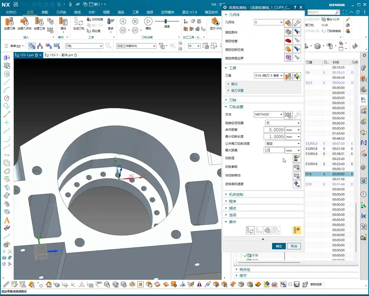
Toolpath Adjustment for Complex Areas
For fillets in corners and edges, if you follow the default path directly, UG might “gouge” the material in the corner or fail to reach it completely. This is when you need to use the trim function to precisely control the toolpath. By adjusting the trim boundaries, you can make the toolpath better conform to the part contour, especially for internal fillets in grooves, preventing overcutting.
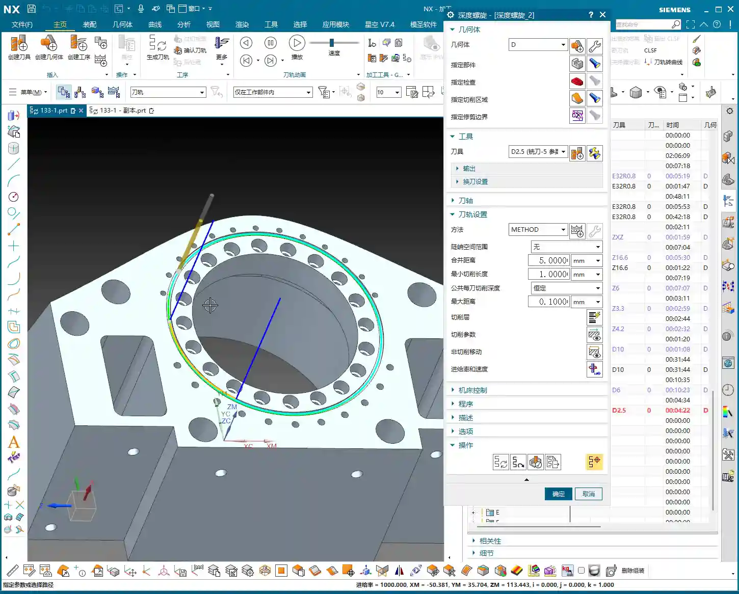
Furthermore, when selecting machining faces, remember this: you don’t always need to select the entire part. Especially in certain situations, for example, when the tool diameter precisely matches the feature size to be machined (e.g., a 2.5mm tool machining an R2.5 fillet), UG might be unable to generate a toolpath. In such cases, you only need to select one side or a single face, and the program will generate smoothly. This is a little trick they don’t teach you in books.
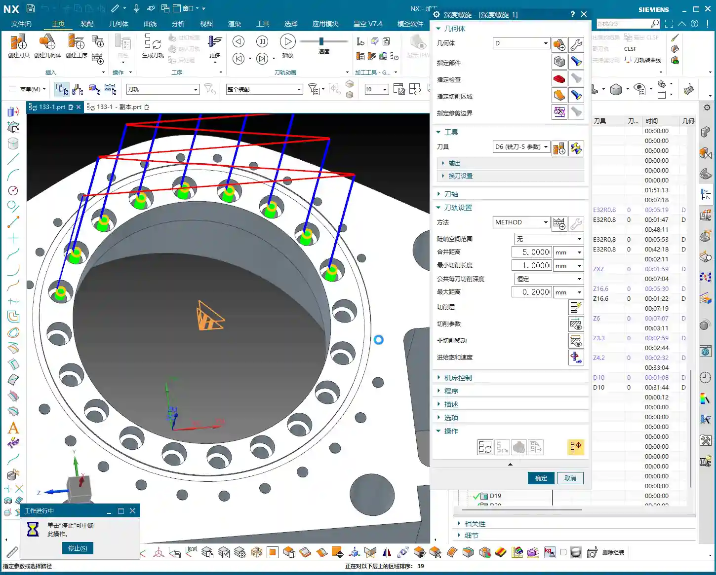
Application of “Constant Z Spiral Machining”
For holes or cavities with moderate depth and a taper, if the “constant Z spiral” toolpath isn’t ideal, you can try “Constant Z Spiral Machining”. This method allows the tool to descend smoothly from top to bottom in a helical motion, resulting in more uniform cutting, reduced tool wear, and improved surface quality. However, remember that if the machining surface is complex, or if there are special requirements, you might need to manually adjust the connection method, or even change to a “follow” toolpath to ensure more logical tool movement.

III. Tolerances and Tool Compensation: Key to Precision Control
When and How to Apply Tool Compensation
Many times, design drawings specify high-precision tolerances for certain dimensions, especially for bores and slots, such as ±0.005 mm (approx. ±0.0002 inch) or even tighter. In such cases, relying solely on the program won’t achieve it; the machine’s inherent precision errors and tool wear will affect the final dimensions. What to do? Apply tool compensation!
Applying tool compensation is simple:
- In UG’s “Machine Control”, find “Tool Compensation Parameters”.
- Select to enable tool compensation; the direction is typically “Left” (G41).
- Here’s the key point: enable tool compensation “before each entry move” and “after each retract move”.
- Set the compensation number to D01 (or D02, D03, depending on your machine and tool numbering).
Note: Programs with tool compensation must be generated and machined separately! Do not mix them with other programs. This is because tool compensation is applied at the machine controller, not by altering the toolpath within the UG program itself. You must first machine the part, then measure it, and based on the measurement results, adjust the corresponding compensation value for D01 in the machine’s CNC system to achieve ±0.005 mm (approx. ±0.0002 inch) level precision.

IV. Program Generation and Simulation Verification
Generation and Inspection
After every parameter change, remember to regenerate the toolpath. UG’s calculation speed depends on the complexity of your part and your computer’s specifications. Waiting a minute or two is normal, don’t rush it. Once the toolpath is generated, don’t just send it to the machine! You must carefully inspect the toolpath, especially the entry, retract, and lift moves, and check for any overcutting phenomena.
I’ll teach you a simple method to identify overcutting: observe the cutting sparks in the UG simulation. If you see unusually large sparks in a particular area, or if the tool motion trajectory is clearly illogical, it’s highly likely there’s overcutting. Of course, the safest approach is to perform a simulation in UG, watching the tool’s movement trajectory step-by-step to confirm there are no collisions or overcutting. If you find overcutting, your first reaction shouldn’t be to change parameters, but rather to check if the ‘part’ faces you selected are correct. Often, this is where the problem lies, leading the tool to cut where it shouldn’t. Ensure ‘lift’ (retract) settings are correct to prevent the tool from scratching the workpiece surface in non-cutting areas.
Special Case Handling: Two-Sided Machining
If you have a part requiring two-sided machining, once one side is finished, flip the part and machine the other side. In this case, you can directly copy the existing program for the first side, then modify the machining direction, or simply “reverse” it directly within the geometry. If selection issues arise, such as features needing machining on both sides, you must ensure you only select the current face to be machined each time, to avoid selection errors that prevent program generation or cause errors. Remember, after every modification, you must regenerate and check – this is an ironclad rule!
Summary: Pitfall Guide
- Tool Selection Must Be Flexible: Don’t blindly stick to the drawings. Select tools with good rigidity and high efficiency based on actual feature dimensions and material. For R2.5 fillets, use a D10; for R9 bores, use a D6/D8.
- Finishing Stock Must Be 0: This is the bottom line for finishing; no remaining stock means meeting drawing requirements.
- Leverage UG Selection Features Effectively: When dealing with ‘precisely matched’ features or complex surfaces, selecting a single side or a local face is often more effective than selecting the entire part.
- Apply Tool Compensation Prudently and Independently: For features with high-precision tolerances (±0.005 mm / approx. ±0.0002 inch level), tool compensation is essential. The compensation program must run independently, with fine-tuning done via compensation values at the machine controller.
- Toolpath Inspection is Paramount: After generating the toolpath, always perform visual checks and simulations for entry, retract, and lift moves, as well as overcutting, to ensure foolproof operation.
- Understand Material Characteristics Well: Cutting parameters vary greatly for different materials (e.g., common aluminum, titanium alloys, high-temperature nickel-based alloys). Adjust cutting speed, feed rate, and tool selection accordingly. This is about experience, and it’s also about cost.
“`
👤 About the Author:
The author is a veteran CNC machining professional with 15 years of industry experience, specializing in UG NX programming. This article is an original work representing personal practical insights.
⚠️ Copyright Notice: Unauthorized reproduction or distribution without prior communication is strictly prohibited.
Leave a Reply