📝 Key Takeaways: Master Wang shares core Siemens NX 2D Dynamic Milling techniques. Learn how to boost Roughing efficiency with “Adaptive Milling” and overcome 3D simulation challenges for 2D programs using “Floor Wall Milling”. In-depth analysis of Stepover, Layers, and critical Retraction parameters to optimize your toolpaths, reduce costs, eliminate inefficiency, and become a machining expert.
Master Wang’s Insight: The Practical Essence of 2D Dynamic Milling
Hello everyone, I’m Master Wang. Today, no fluff, just practical insights! Many ask me, ‘Master Wang, what’s the real difference between ‘Planar Milling’ and ‘2D Dynamic Milling’ in NX, and how can we use them efficiently?’ Listen up! Today, I’m going to break it down for you, revealing practical tips you won’t find in textbooks!
There’s a command in NX called “Solid Profile 3D”—we’ll set that aside for now, it’s a bit complex. Today, let’s dive straight into 2D Dynamic Milling, also known as 2D Adaptive Milling in NX. Different names, but the principle and objective are the same: during Roughing, it aims to create smoother toolpaths, minimize sudden changes in cutting force, and improve both efficiency and tool life.
Key Change: From “Follow Periphery” to “Adaptive Milling”
Previously, with Planar Milling, toolpaths were typically parallel, and the cutting pattern was often “Follow Periphery”. When encountering corners, the tool would suddenly engage with a full Depth of Cut, leading to chipping. 2D Dynamic Milling is different; its biggest and most crucial change lies in its cutting pattern.
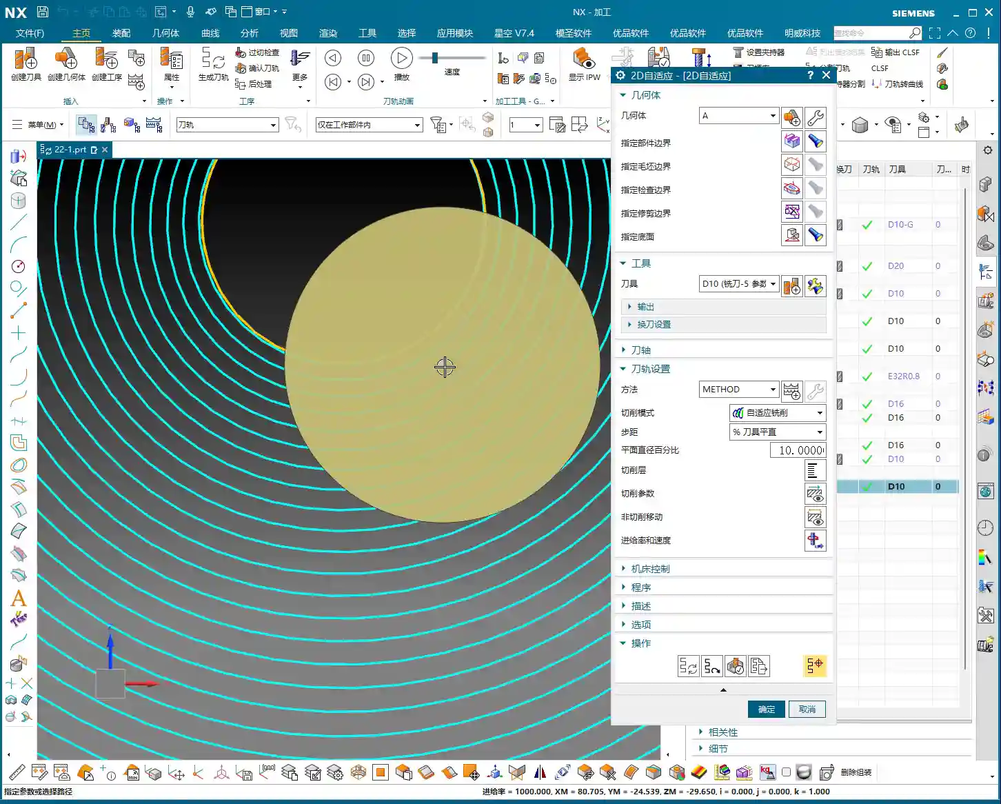
Select 2D Dynamic Milling (or 2D Adaptive Milling), and you’ll find its interface is almost identical to Planar Milling. That’s right, it evolved from Planar Milling. But, if you click in and change the cutting pattern from “Follow Periphery” to “Adaptive Milling”, this feature completely transforms!
Changing just this one parameter alters the tool’s cutting method. It strives to maintain a constant cutting width, using small Stepover and high feed rates to create a “peeling” type of toolpath. This effectively prevents the tool from engaging with a full Depth of Cut, making it particularly suitable for deep pocket Roughing and hard material machining.
Toolpath Boundaries and Floor Definition
Defining the toolpath range is similar to Planar Milling.
- Part Boundaries: Specify the boundary curves of the area you want to machine. Make sure to select them precisely; don’t over-mill or under-mill.
- Floor: Select the bottom face for machining. This face defines your machining depth. Beginners often make mistakes here; selecting the wrong one can lead to over-machining (milling through) or not reaching the desired depth. Remember, choose the face you ultimately intend to machine to.
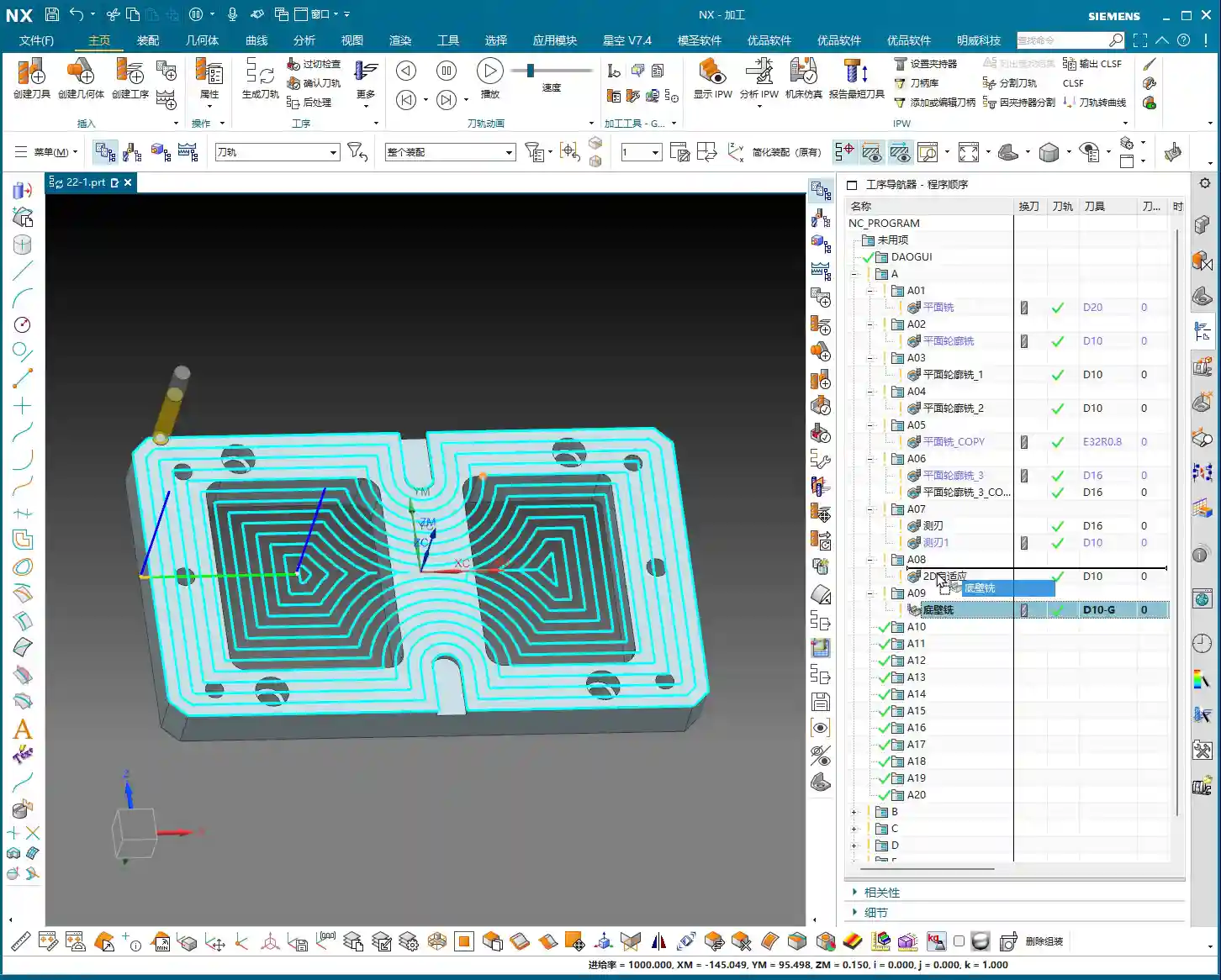
For the tool, just pick a common one for now, like a D10 end mill (10mm diameter). Generate the program first, and then we’ll fine-tune it step-by-step.

Simulation: Avoiding the “No Stock” Pitfall
Alright, the program is generated. Let’s run a simulation to check the results. Click “Tool Path Verification” and then select 3D Simulation. You might find it throws an error! It’ll say “No Stock” or fail to simulate. This is a common pitfall for many beginners, and textbooks often don’t tell you about it.
NX 2D Program Simulation Pain Point: Doesn’t Recognize Solids, Only Wires
Why the error? Because 2D programs, like Planar Milling, only recognize wires, not solids. They don’t know what your stock looks like, so they can’t perform a 3D solid cutting simulation. If you click ‘Simulate’ directly at this point, the system gets “confused”.

Master Wang’s Secret: Add a “Floor Wall Milling” Operation as Stock
The secret to solving this is simple: before your 2D Dynamic Milling program, add a “Floor Wall Milling” operation to serve as your stock reference!
- Create a new “Floor Wall Milling” operation, define the part and floor arbitrarily, and select any tool.
- Generate this “Floor Wall Milling” program.
- Drag your 2D Dynamic Milling program underneath this “Floor Wall Milling” program.
Now, select your 2D Dynamic Milling program again and run a 3D simulation. You’ll see a miracle happen! The simulation works normally! This is because 2D Dynamic Milling “inherits” the stock state after the “Floor Wall Milling” operation, so it now knows where to start cutting. This little trick will save you a lot of debugging time!
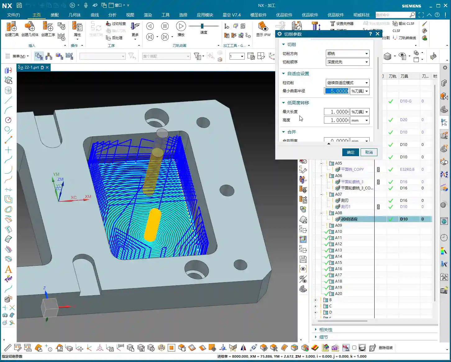
Through simulation, you’ll observe the tool descending in a helical motion, then expanding outwards within the cavity like a snail shell, with a very stable cutting process. That’s the beauty of dynamic milling! It equalizes the tool’s cutting load, which allows for higher cutting parameters and boosts machining efficiency.
Core Parameter Analysis: Stepover, Layers, and Retraction Control
NX has parameters galore, but only a few core ones truly impact machining quality and efficiency. Today, we’ll focus on dynamic milling’s key parameters.

1. Stepover: Cutting Width and Efficiency
Stepover is the distance the tool moves sideways with each pass.
- Percentage: The default is usually around 10% of the tool diameter. For example, for a D10 tool (10mm diameter), 10% is 1mm. This value determines your cutting width and toolpath density. A small Stepover results in dense toolpaths and a better surface finish but takes longer; a large Stepover increases efficiency but might leave uneven stock after Roughing.
- Constant: You can also set it to a fixed value, such as 0.5mm. Whether to use a percentage or a fixed value depends on your tool and material. For Roughing, generally choose a larger Stepover to improve efficiency, but don’t exceed 30-40% of the tool’s effective cutting edge width, or it could lead to Chatter or tool breakage.
2. Layers: Roughing Depth Strategy
Layers, also referred to as Depth per Cut, controls the tool’s multi-level cutting in the Z-axis direction.
- If you set a specific value, such as “20”, it will divide the total machining depth into 20 layers for processing.
- However, in Roughing, for maximum efficiency, we usually set this value to 0. Setting it to 0 means one continuous cut to depth (or “finish to floor”). The tool will helix down from the top and then machine directly to the defined floor depth, reducing retractions and layering. This is crucial for boosting efficiency in dynamic milling!

3. Minimum Corner Radius: Corner Smoothness
This parameter is found on the “Strategy” page. It defines the minimum corner radius the tool can follow when turning.
- The default is typically 5% of the tool diameter. For a D10 tool (10mm diameter), this means a 0.5mm corner radius.
- A larger value results in smoother corners and less force on the tool; a smaller value creates sharper corners, but the tool might experience higher forces in those areas. Typically, keeping the default is fine; consider adjusting only for specific Corner Cleanup requirements.
4. Retraction Control (Height & XY Transfer): Efficiency Killer or Safety Net?
Tool retraction is a critical aspect of machining, directly impacting idle travel time and overall efficiency.
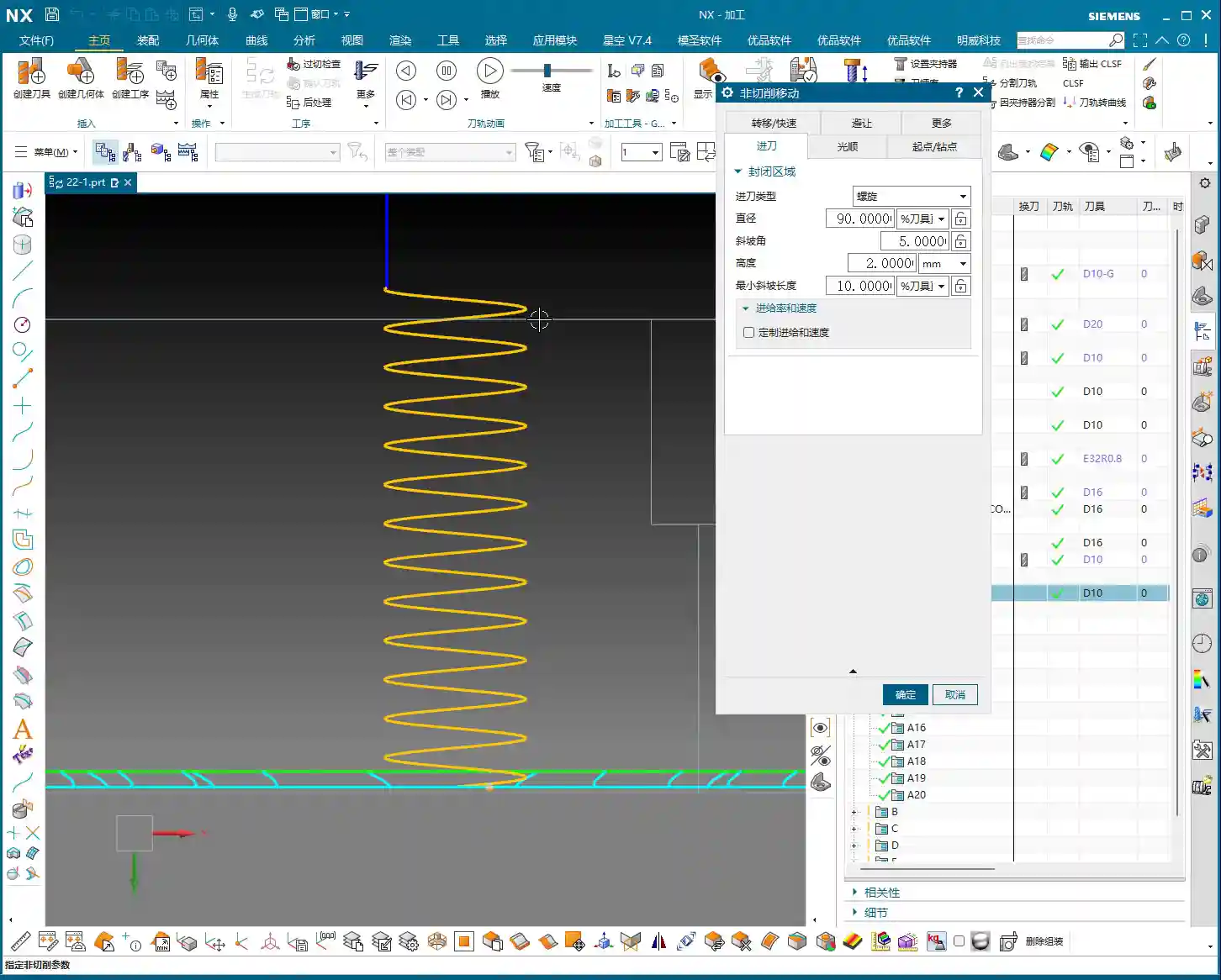
- Height: This controls the tool’s retraction height when moving from one cutting area to another within the same layer. The default is 1mm, meaning it retracts 1 millimeter each time. Setting this value too high increases idle travel time; setting it too low risks collision with the workpiece, which is unsafe. The default 1mm is generally sufficient.
- XY Transfer / Global Retraction: This parameter typically appears as a very large percentage, such as 5500%. It controls the retraction strategy between different cutting regions or between different layers.
- Larger Value: The tool is more inclined to avoid retracting, opting for “smooth connection” paths, moving quickly across the workpiece surface as much as possible, reducing the number of retractions. This is KEY to boosting efficiency! I usually set it to a very high value, like 10000, or even higher, to ensure more continuous tool motion.
- Smaller Value: The tool will retract very frequently, even for short movements. This causes idle travel time to increase exponentially, resulting in extremely low efficiency and machining times that will drive you crazy!
Therefore, for this parameter, NEVER set it too low! Try to give it a large value, allowing the tool to move quickly and continuously in the XY plane, which will significantly improve your machining efficiency.
Side Wall Corner Cleanup: Another Advantage of Dynamic Milling
Dynamic milling not only efficiently performs Roughing on planar surfaces but also offers unique advantages in side wall Corner Cleanup. Due to its “adaptive milling” characteristics, the cutting load on the tool in corners is well-controlled, minimizing the risk of chatter marks and ensuring uniform stock for subsequent Finishing passes.
If you notice during simulation that the side walls don’t show a “highlighted” sheen, it indicates that there is still stock remaining on the side walls. This is normal; Roughing aims to quickly remove most of the material, preparing for the Finishing pass. We’ll cover Finishing toolpaths in detail next time.
Summary: Pitfall Avoidance Guide
- Essential Parameter Change: The core of 2D Dynamic Milling is to change the cutting pattern to “Adaptive Milling”.
- Simulation Trick: Before running a 3D simulation for a 2D program, always add a “Floor Wall Milling” operation beforehand as a stock reference; otherwise, it will error out.
- Efficiency Boost: During Roughing, set Layers to 0 (one continuous cut to depth), and adjust the Stepover appropriately based on the material and tool.
- Reduce Retractions: Maximize the percentage value for “XY Transfer” (or “Global Retraction”), for example, 10000, to ensure more continuous tool motion and reduce idle travel time.
- Stock Check: After simulation, observe if the part surface has a “highlighted” sheen. Areas without sheen indicate remaining stock, requiring a subsequent Finishing pass.
These are experiences I, Master Wang, have accumulated over more than a decade in the trenches. I hope they are helpful to you, the next generation! Practice makes perfect; get your hands dirty, observe closely, and you’ll become a true machining expert!
👤 About the Author:
The author is a veteran CNC machining professional with 15 years of industry experience, specializing in UG NX programming. This article is an original work representing personal practical insights.
⚠️ Copyright Notice: Unauthorized reproduction or distribution without prior communication is strictly prohibited.
Leave a Reply