📝 Key Takeaways: Master Wang guides you through every meticulous step of multi-process part roughing programming, from tool selection to stock management and toolpath optimization. Deep pocket helical milling and dynamic stock definition are especially critical for boosting efficiency and preventing tool crashes. Remember, hands-on experience is paramount—don’t just rely on software simulations; look for the actual cutting sparks!
Sit tight, folks! Today, Master Wang is going to lay out the ins and outs of multi-process roughing. We’re picking up where we left off, and this time it’s all practical wisdom—stuff you won’t find in textbooks. Multi-process part roughing is all about finesse, not brute force.
NX Roughing: Tool Selection First – The Ø32mm Cutter Breakthrough
Tool Selection Strategy and Path Planning
Listen up! For roughing the external contours of this part, we typically start by testing with a Ø32 R0.8 end mill. Don’t rush into using larger cutters like a Ø63; you need to understand the terrain first. Smaller cutters are more versatile and can handle tough spots without issues. If you jump straight to a large cutter and take too aggressive a Depth of Cut (DOC), you risk snapping the tool or, worse, scrapping the workpiece – and that’s real money lost!
When performing Planar Milling in NX, the cutting direction is paramount when selecting geometry boundaries. You must ensure the tool begins cutting from the outside of the stock and moves inwards. Otherwise, if it plunges directly into the material, that’s what we call a “tool crash”—can your spindle handle it? Can your workpiece handle it? This is fundamental; don’t get confused.

Boundary Extension and Stock Allowance Control
Sometimes, the boundary lines you’ve drawn result in a toolpath that’s “just a hair short”—it doesn’t fully cover the area, or the tool doesn’t fully exit the workpiece. In such cases, you need to use NX’s “Trim and Extend” function. Extend the boundary lines appropriately so the tool can smoothly enter and safely exit. Here, for instance, we sometimes have to push the cutting length to 100% or even more (e.g., 150%) to ensure a clean sweep with no remaining material.
How much stock allowance should you leave for roughing? Side walls typically get 2mm, while the bottom surface can initially be set to 0mm, or 1mm, depending on your subsequent finishing tool and strategy. For this job, we’ll leave no allowance on the bottom for now and address it in the next operation.
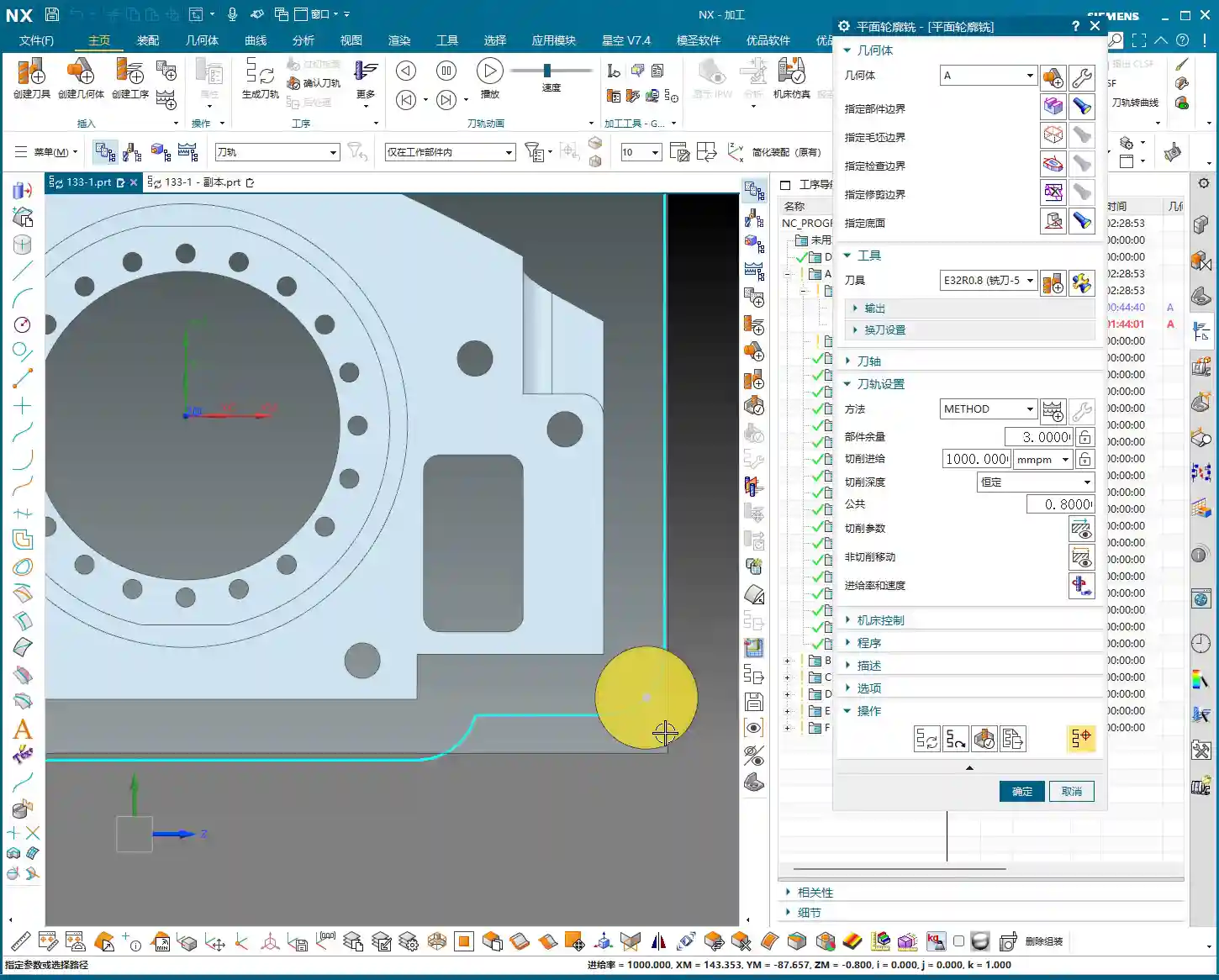
Regarding Depth of Cut (DOC), setting it to around 4mm is usually good. Choose Mixed Cut for the cutting method. This ensures efficiency while distributing the load evenly on the tool, extending its lifespan. Don’t underestimate these details; they’re all born from experience.
Helical Milling Deep Pockets: Details You Can’t Overlook

Deep Pocket Helical Milling Techniques
When tackling deep slots or holes, Helical Milling is your go-to weapon; it’s a hundred times better than just plunging straight down. Here, we’ll use a Ø16 R0.8 end mill because it’s better suited for these relatively narrow internal features than a 32mm cutter.
When machining geometric surfaces, remember to select the tangent faces. This ensures the toolpath hugs the slot walls tightly, resulting in a much better finish. Don’t pick the wrong faces; a slight error can lead to a huge deviation.
This slot is quite deep, and machining it in a single pass can easily overload the tool. We can adopt a “half-depth-per-side” machining strategy, meaning we machine one half of the depth, then the other. This reduces the load on the tool for each pass, making it easier on both the tool and the machine, and ensuring better machining quality.
Z-Axis Height and Depth of Cut (DOC) Fine-Tuning
The starting Z-height for helical entry must be precisely calculated, not just guessed. I usually leave a little extra, for instance, setting a starting height of 3.5mm. This prevents the tool from directly impacting the stock, avoiding those “tool crash” incidents we discussed earlier.
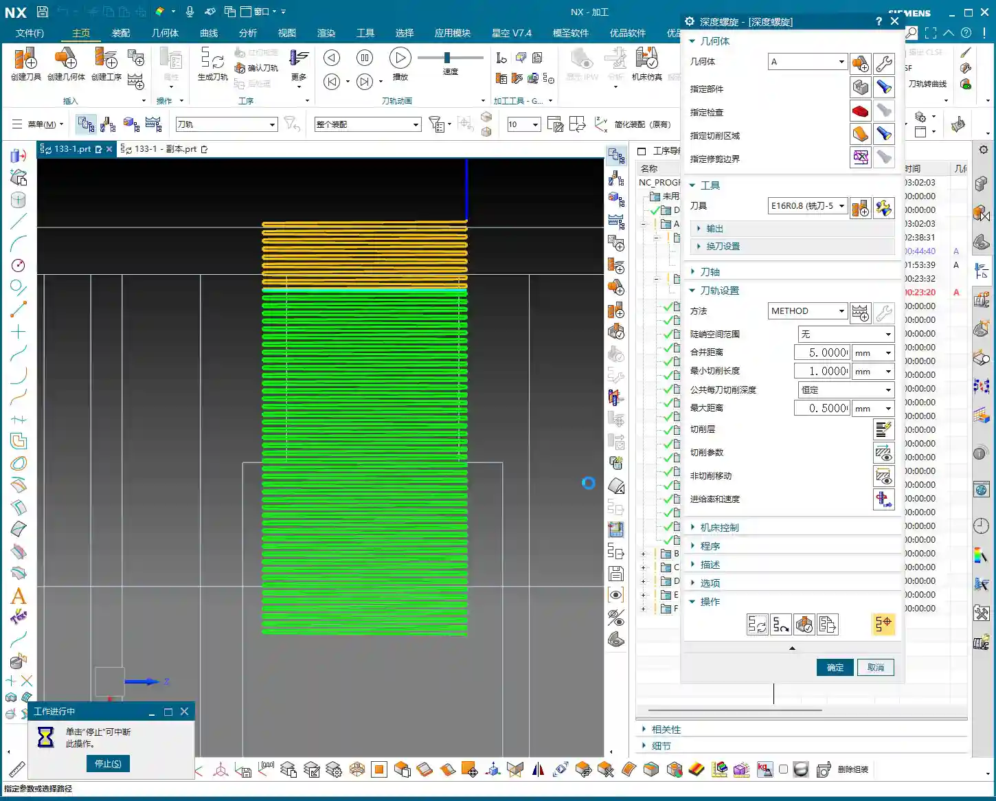
The helical angle and Stepover parameters need careful adjustment based on your material and tool. Don’t be fooled by impressive software simulations; the real cutting sparks and machine sounds are your most accurate feedback. The audio mentioned a 0.3mm cutting amount, but if the helical angle is too large, the tool load will be uneven. You need to iterate and test until the toolpath is stable and transitions smoothly.
This area is mainly for weight reduction, so dimensional accuracy isn’t as critical. However, don’t get sloppy with the machining process, or else a high scrap rate will have your boss calling you in for a talk.

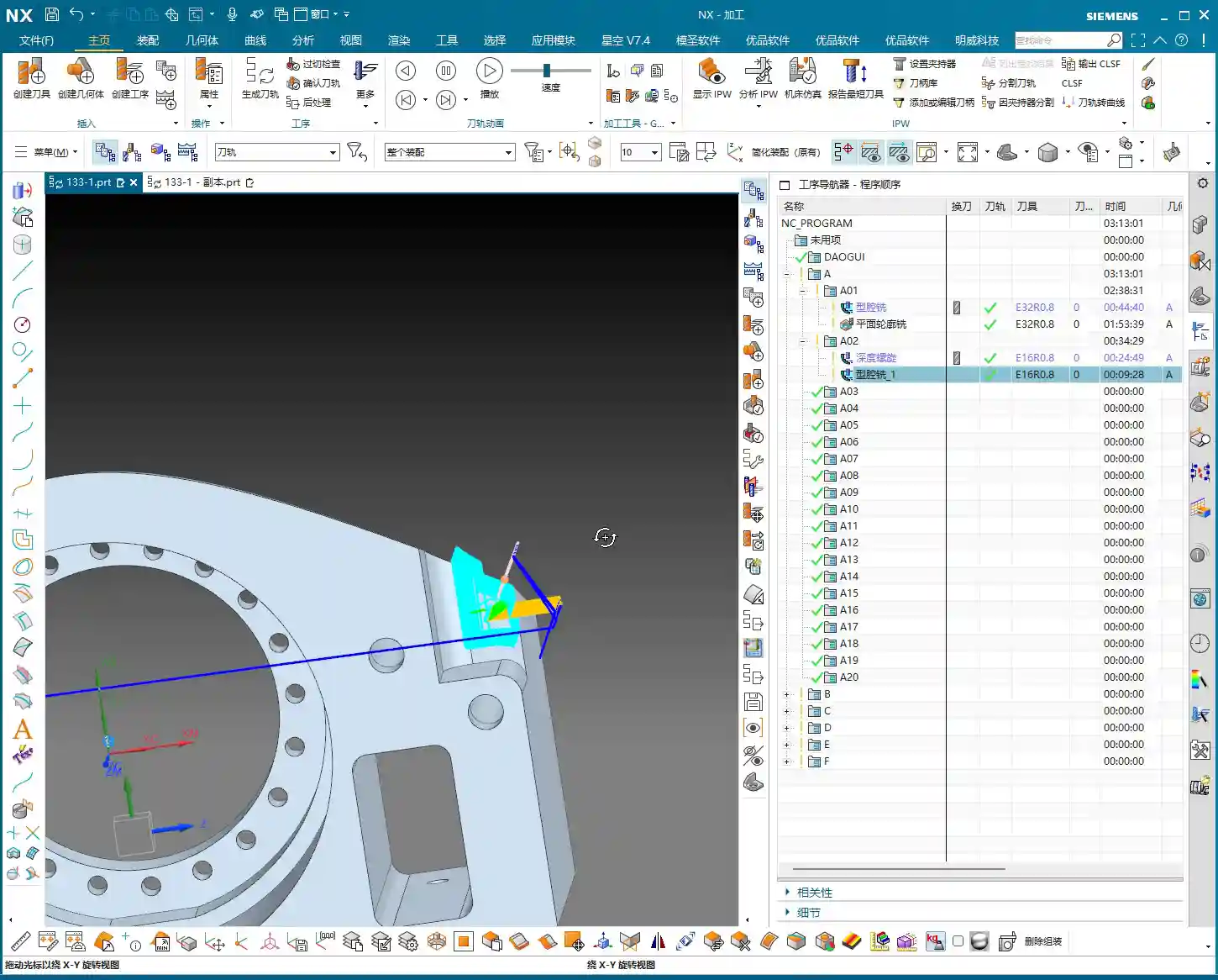
Stock Management: Intelligent Avoidance, Efficient Machining
Dynamic Stock Definition
In multi-process machining, the most easily overlooked yet crucial aspect is stock (Blank/Stock) definition! It’s not static; it’s dynamic. After the previous operation is complete, you must re-extract or update the stock model based on the material actually removed. If you continue using the old stock, subsequent toolpaths will either be air cuts or crashes—there’s no certainty.
NX has a useful function called “Replace Face”, which allows you to quickly replace the corresponding faces of the original stock with the machined model faces. This trick ensures that your subsequent operations calculate toolpaths based on the latest workpiece state—a secret weapon for avoiding air cuts and boosting efficiency.

Allowance and Tool Compensation
The stock allowance settings for new operations must be appropriate, otherwise you’ll find the tool either cutting air or cutting too much. For example, leaving 2mm on the sides is to provide enough room for finishing. For some internal machining areas, sometimes we’ll initially leave a 5mm allowance, then fine-tune it during semi-finishing or finishing passes.
Don’t forget your R0.8 tool; it can take a bit more material when cutting sidewalls, so leaving a 1.3mm allowance is also acceptable. These decisions are based on the tool’s characteristics, so master them flexibly.
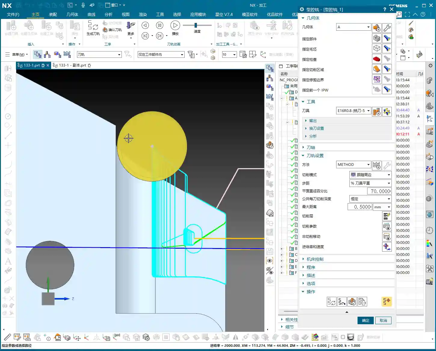
Toolpath Optimization: Path and Allowance, Striving for Perfection
Tool Entry/Exit Direction and Trajectory
When reviewing toolpaths, a quick glance isn’t enough; you need to closely observe the tool entry and exit directions. Different settings, especially the “push cut” direction, can lead to subtle differences between simulation and actual machining paths. Sometimes, just this small difference can cause machining defects. Therefore, during simulation, be sure to rotate the model from multiple angles and inspect it carefully.
For areas with complex boundaries, the cutting length percentage parameter requires iterative adjustment. You might start by trying 70%, find it hasn’t cut completely, then adjust to 90%, or even over 100%, until the tool fully covers or completely exits the workpiece. If this isn’t done right, you’ll easily end up with steps or an unclean cut.
Experience and Parameter Adjustment
I always tell you, programming parameters aren’t meant to be memorized blindly! Textbook theory is fundamental, but in practice, you must judge and adjust based on the machine’s actual condition, material properties, cutting sparks, and the sound of the machine. This is where NX programming’s flexibility comes in; it allows you to solve countless real-world machining issues, not found in textbooks, by fine-tuning relative position parameters.
Another good habit is stock organization and management. I personally prefer to place stock files after sequence numbers like 100, 101. This makes them clear at a glance, easy to find and manage. Developing such good work habits can significantly boost your efficiency.
Summary: Pitfall Avoidance Guide
Everything I’ve shared today comes from my fifteen years of hard-won experience, so make sure you remember it:
- Stock management is critical: For multi-process machining, you must dynamically update the stock model; otherwise, you’ll either crash the tool or make air cuts, wasting time and scrapping parts.
- Toolpath boundaries must be extended: Especially for roughing, the tool must fully enter and exit the workpiece to avoid leaving remnants or steps, which would impact subsequent finishing passes.
- Tool entry points must prevent crashes: Z-axis safety height and helical entry parameters need fine-tuning to eliminate direct tool impact with the stock—that’s a sure way to snap a tool in seconds!
- Parameters require flexible adjustment: Combine textbook theory with actual cutting sparks and machine sounds for judgment; don’t be rigid. The machine won’t lie; it will tell you what’s wrong.
- Leave sufficient and correct allowance: Too little makes finishing difficult and accelerates tool wear; too much wastes time and increases costs. Plan logically based on the tool and subsequent operations.
- Understand push cut direction: For complex geometries, the tool’s push cut direction can affect the final result and surface quality; pay special attention during simulation.
Process this information well, and spend more time experimenting on the machine. Only then can you truly become a master machinist!
“`
👤 About the Author:
The author is a veteran CNC machining professional with 15 years of industry experience, specializing in UG NX programming. This article is an original work representing personal practical insights.
⚠️ Copyright Notice: Unauthorized reproduction or distribution without prior communication is strictly prohibited.
Leave a Reply