📝 Key Takeaways: **
Multi-Process Roughing – Sequence 2: A Practical Guide
Hello everyone, Master Wang here. Picking up where we left off, the first machi…
[VIDEO_HERE]
Hello everyone, Master Wang here. Picking up where we left off, the first machining sequence is complete. Now, we’re diving into the second roughing sequence. Listen up: this is a critical step in multi-process machining. If you don’t get the details right now, you’ll be dealing with rework during finishing!
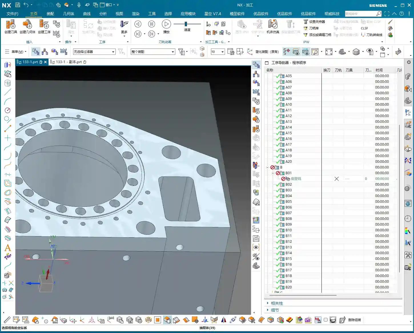
Sequence 2 Machining: Overview and Strategy
For this second sequence, the primary goal is to rough out the part’s main face (typically the upward-facing machining surface), internal cavities, and top surfaces. Remember, the machining order is crucial: first, perform Face Milling to level the large flat surfaces; then, proceed with Roughing the internal cavities to remove the bulk of the material; finally, it’s common practice to consider heat treatment to stabilize the part’s properties before moving to Finishing pass. This is the most reliable process flow.
The “Soul” of Siemens NX Coordinate Systems and Stock Setup
The Secrets of the Work Coordinate System (WCS)
Every time you switch sequences, or even subdivide into different machining strategies, the Work Coordinate System (WCS) must be re-evaluated and precisely positioned. This is the first critical gate for ensuring machining accuracy. For Face Milling, you can set the WCS at a corner or along an edge of the part for ease of operation.
Master Wang’s Secret Tip: Don’t just rely on software simulation and think the WCS can be anywhere. An inaccurate WCS setup makes even the most beautiful tool path useless! Especially when you get to internal Roughing, make sure to position the WCS exactly at the “center” of the part. Otherwise, the tool will “get lost,” leading to eccentricity at best, or a tool crash and scrapped part at worst! This is a lesson many newcomers learn the hard way!

Precisely Defining Stock: Residual Material is No Longer a Mystery
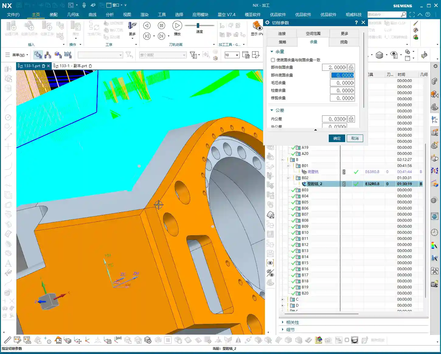
For this sequence, we’ll directly use the stock state after the first machining sequence, which saves the hassle of re-modeling. The key is to understand how much material is currently remaining on the stock and how much allowance you plan to leave for Finishing pass.
For example, after measurement, we find this face has a remaining height of 24.5mm (approx. 0.96 inch). I plan to leave 2mm (approx. 0.08 inch) of allowance for Finishing pass. Therefore, for Face Milling, I need to machine down to 24.5mm – 2mm = 22.5mm (approx. 0.88 inch). You can directly copy and paste this value in NX to ensure accuracy. Don’t underestimate these few tenths of a millimeter; they accumulate into precision issues!
Practical Tip: Every time you transition between machining sequences, re-measure the actual stock dimensions instead of blindly trusting blueprint values or theoretical values from the previous program. Real-world data is what guides you to create the most optimal tool paths. In NX, you can use the “Offset” function to precisely offset a datum plane upwards or downwards by the required allowance, using it as a Depth of Cut reference.
Face Milling Operation: The Art of Aggressive Material Removal
Tool Selection and Parameter Configuration
For Face Milling, we’ll go with a large tool. This time, I’ve chosen a D63 face mill with 0.8mm corner radius inserts. A “Zig” or “Zigzag” cutting pattern will be efficient and straightforward. For cutting parameters, set feed rates and spindle speeds to conventional values initially. But remember, when the machine is actually running, you must observe the cutting sparks and listen to the cutting sound, then fine-tune as needed. Textbook parameters are just a reference; real-world conditions are always changing.

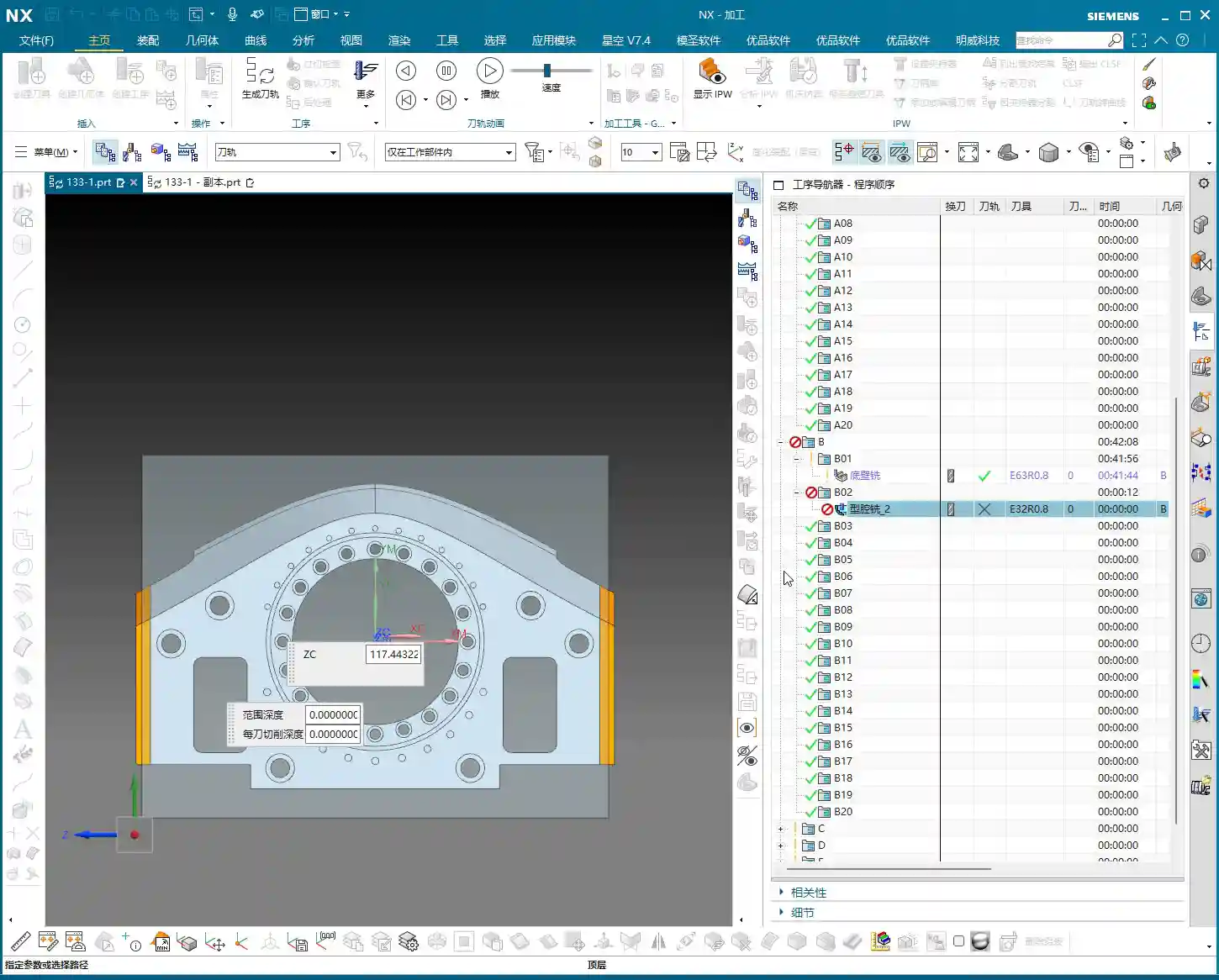
Critical Depth of Cut and Material Allowance Control
As mentioned earlier, the target Depth of Cut (DOC) is 22.5mm. For the first pass, you can go slightly shallower, perhaps 0.5mm (approx. 0.02 inch), allowing the tool to “test” the surface, reduce impact, and protect the inserts. Subsequent passes can then use the normal DOC. Once the entire Face Milling program is complete, that shiny surface will give you peace of mind.
Words of Experience: During Face Milling, you can leave a little extra material allowance, even 0.1-0.2mm (approx. 0.004-0.008 inch), to ensure there’s enough material for the subsequent Finishing pass and to prevent chipping. However, don’t leave too much, as it will impact Roughing efficiency. Especially for difficult-to-machine materials like titanium alloys and superalloys, the Depth of Cut on the first pass must be carefully controlled to minimize impact and extend tool life.
Internal Roughing: The Starting Point for Precision Machining
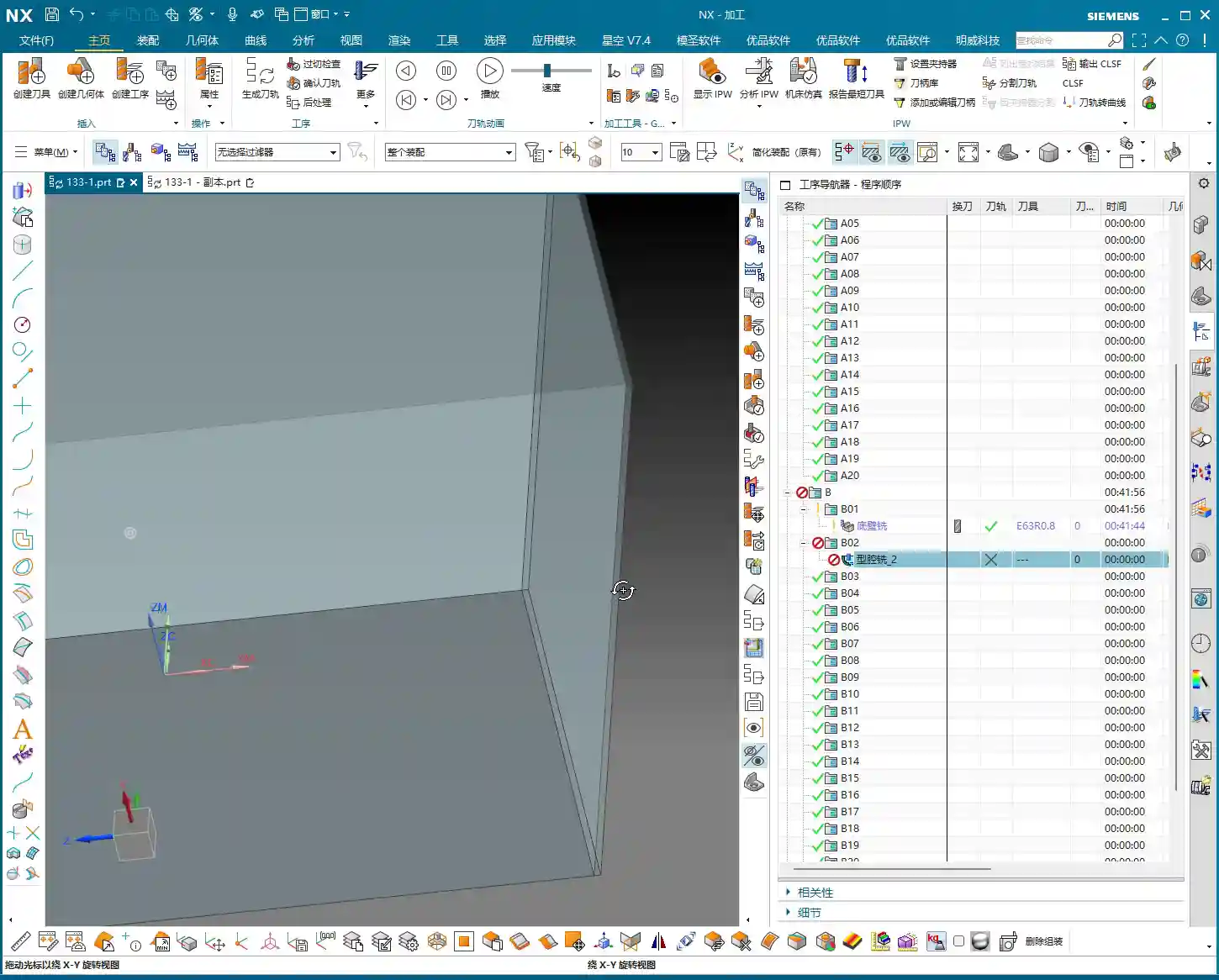
WCS Reset: The Lifeline for Internal Machining
After Face Milling is complete, our stock has changed. Now we begin internal Roughing, which is a very crucial stage. Listen carefully: for internal Roughing, you MUST reset the WCS to the “center” of the part! Do not use the WCS from the Face Milling operation; that will cause tool path deviation, resulting in holes or cavities that are not round, or are incorrectly positioned. This is the most common mistake and the most overlooked area for newcomers.
Master Wang’s Warning: If the WCS for internal Roughing remains in a corner, it could lead to eccentricity and a scrapped part at best, or a tool crash and machine damage at worst! Don’t make such amateur mistakes; we’re talking about equipment worth hundreds of thousands of dollars.

Boundary Trimming and Auxiliary Surface Construction
For internal Roughing, we need to use “trim boundaries” to precisely control the tool’s machining range. Some areas require material removal, while others have already been machined or don’t need cutting. This is where auxiliary surfaces come into play.
How do you do it? It’s simple: use the “Thicken” or “Offset” commands in NX to create new auxiliary surfaces along the edges of surfaces where material allowance needs to be left or where the tool needs to avoid. These auxiliary surfaces become our “trim boundaries.” They tell the tool: “Don’t cross this line! Work only within these specified regions!” This not only prevents the tool from cutting unintended areas but also significantly reduces air cutting, greatly improving machining efficiency.
Efficiency Boost: Judicious use of trim boundaries not only precisely controls the machining area but also drastically cuts down on air cutting time. The electricity and time saved are direct cost savings. For complex cavities, planning trim boundaries in advance ensures smoother and more effective tool paths.
Stock Management and Program Verification
Clean Up Redundant Stock for Clean Data
During programming, it’s sometimes easy to accidentally copy redundant stock geometry or retain stock that was meant to be deleted from a previous operation. This superfluous data can interfere with NX’s calculations, leading to incorrect tool path generation or even errors. Therefore, regularly checking for and deleting excess stock geometry to keep your data clean and organized is a good habit.
Programming Principle: Stock files must be singular and accurate. Excess junk data will interfere with system judgment, leading to disorganized tool paths or even incorrect program calculations. Especially when transitioning between multi-process sequences, always ensure the uniqueness and correctness of your stock definition.

Tool Path Simulation and On-Site Verification
Once the program is complete, tool path simulation in NX is a mandatory step. It helps you identify potential over-cuts, under-cuts, or collision risks. However, I must emphasize this: do not rely entirely on software simulation! Simulation is, after all, virtual.
Master Wang’s Expertise: No matter how good the simulation, you still need to observe the machine’s cutting sparks and listen to the cutting sound! These are “languages” you can’t learn from textbooks; they tell you if the tool is cutting properly, if inserts are chipping. Newcomers might not understand it, but over time, you’ll be able to judge if cutting is normal, if the tool is worn, or even anticipate internal inclusions in the material, just from the spark color and sound intensity. That’s real-world experience!
Summary: Pitfall Avoidance Guide
- WCS positioning is paramount! Every time you switch sequences, especially for internal machining, always check and accurately place the WCS at the part’s center. This is fundamental for ensuring accuracy.
- Stock definition must be precise! Allowance calculations cannot be sloppy; they must be determined based on actual measurements and Finishing pass requirements, directly impacting subsequent accuracy and tool life.
- Trim boundaries are powerful tools! They are key to optimizing tool paths, avoiding air cuts, and preventing over-cutting. Make good use of auxiliary surfaces to construct precise trim boundaries.
- Simulation verification is essential! After every program modification, especially for critical parameters, always perform NX simulation verification and combine it with judgments based on actual cutting sparks and sounds.
- Clean data is foundational! Regularly clean up redundant stock geometry to maintain a clean programming environment and avoid unnecessary errors.
👤 About the Author:
The author is a veteran CNC machining professional with 15 years of industry experience, specializing in UG NX programming. This article is an original work representing personal practical insights.
⚠️ Copyright Notice: Unauthorized reproduction or distribution without prior communication is strictly prohibited.
Leave a Reply