📝 Key Takeaways:
Roughing Practicalities for Mold Components
Hello everyone, I’m Master Wang. Today, let’s talk about programming the roughing operation f…
[VIDEO_HERE]
Hello everyone, I’m Master Wang. Today, let’s talk about programming the roughing operation for this mold component. Don’t let its small size fool you; there are many intricacies involved, and a slight oversight can lead to significant problems. Listen up.
Part Analysis and Stock Definition
In-depth Analysis of Part Features
When you get a new part, the first thing you need to do is examine it thoroughly. Don’t rush straight into it; that’s what novices do.
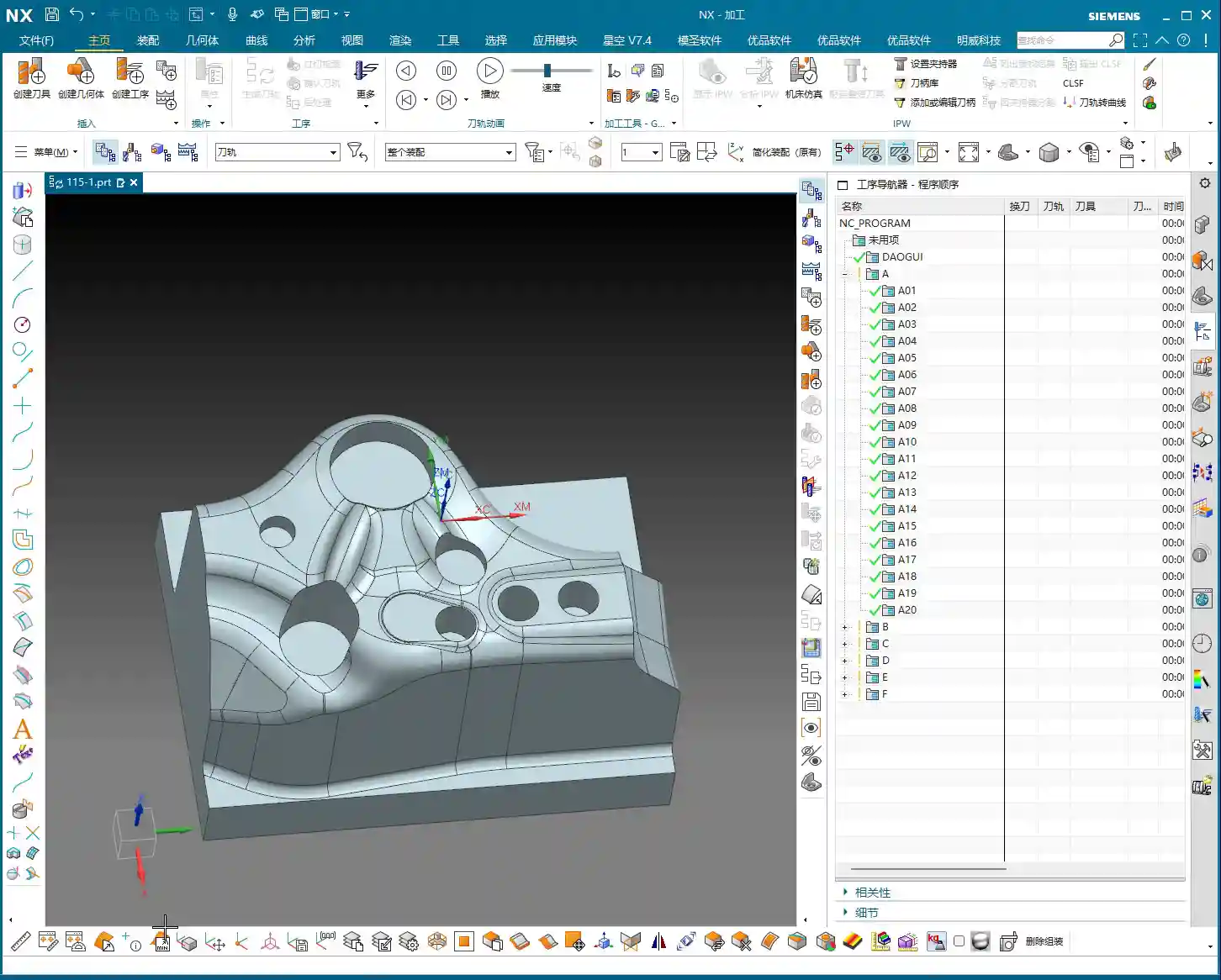
- This small mold component, while not large overall, is complex despite its size.
- Looking at it, there are some holes. During roughing, we can initially ignore them, or even patch them up directly to reduce air cuts.
- The most critical features are these fillets (R-radii). After careful analysis, most of them are R4. This value is the decisive factor for selecting our roughing tool.
- There are also some sloping surfaces and undercut features. These are prime areas for issues. Don’t just rely on pretty toolpath simulations in Siemens NX; the sparks from actual machine cutting are the only true test! If these areas aren’t handled correctly, it can lead to over-machining or undercuts at best, or tool crashes and scrap at worst.
- Some very minor tool marks or small undercuts, if they don’t significantly affect final accuracy and can be covered by subsequent finishing passes, can be temporarily ignored during roughing. But always keep them in mind.

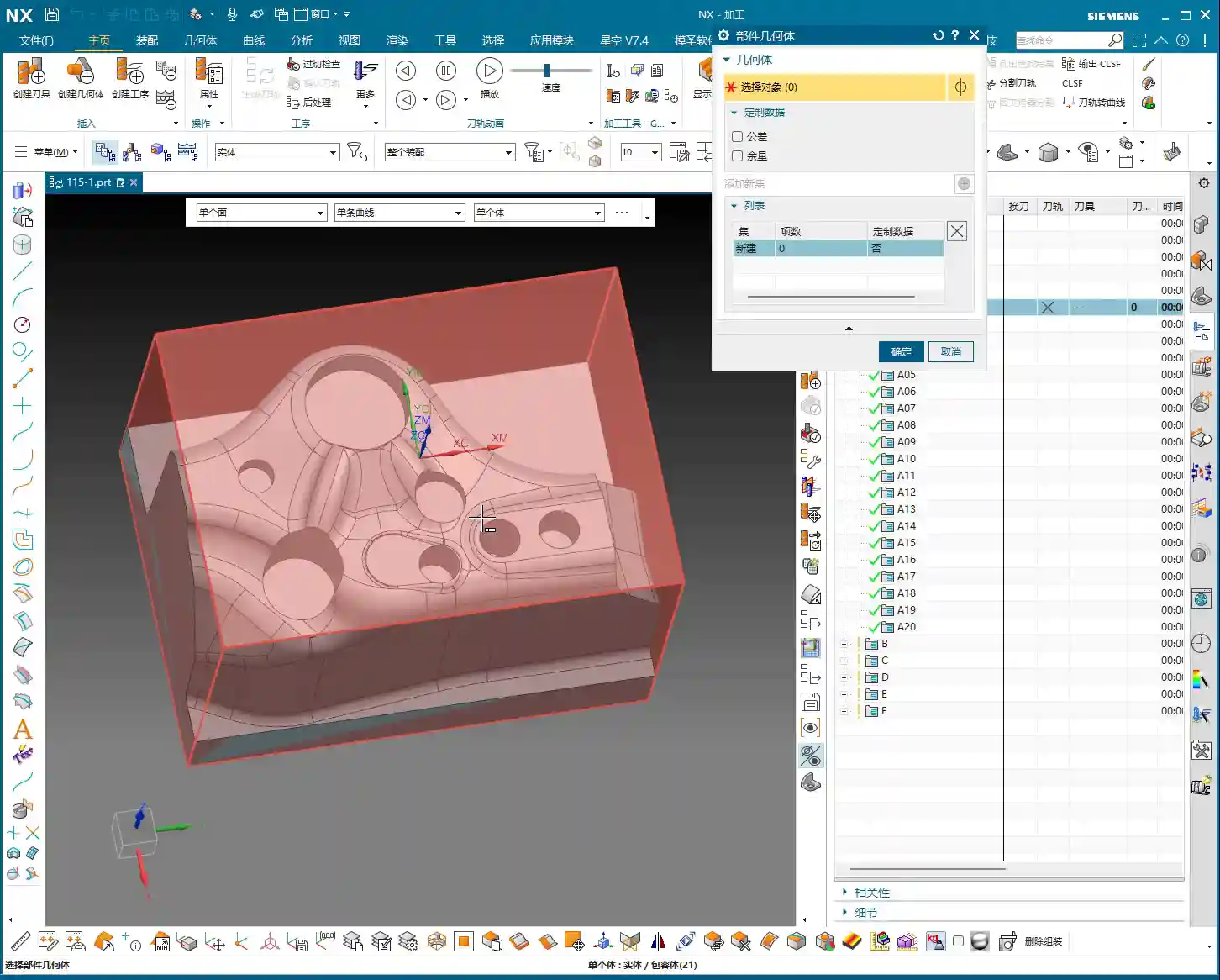
Scientific Stock Definition
Stock definition is the starting point for machining, and it cannot be overlooked.
- The Coordinate System must be clearly defined. This is the datum for all machining programs. If it’s off, everything that follows will be incorrect.
- The stock dimensions should be slightly larger than our part. Especially in the Z-axis direction, I usually leave an extra 1-2 mm (approx. 0.04-0.08 inch) of material. Why? For easier clamping and to provide some leeway for subsequent machining—safety first!
- When setting up the stock, create it directly using Siemens NX’s geometry or automatic blank functions, ensuring it covers the entire machining area.
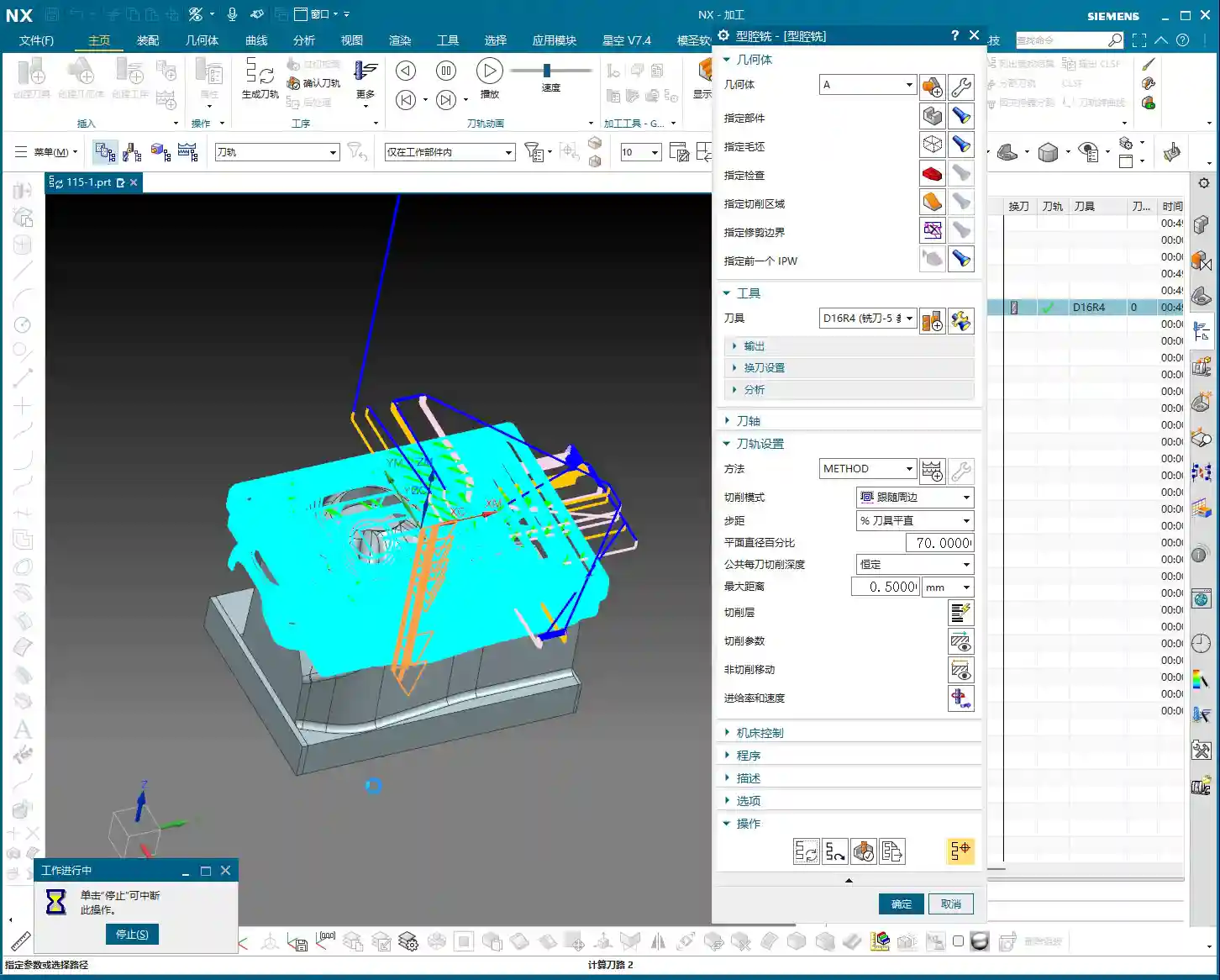
Roughing Tool Selection and Machining Strategy

Matching Fillet Radii with Roughing Tools
Tool selection is an art, not a guess; it requires a basis.
- Since the smallest fillet radius on our part is R4, the radius of the roughing bull nose end mill must be smaller than R4. This ensures a suitable amount of material is left in the corners for subsequent semi-finishing and finishing passes.
- I recommend choosing a 16mm (approx. 0.63 inch) diameter bull nose end mill with a 2mm (approx. 0.08 inch) corner radius (i.e., 16R2). This tool offers sufficient strength and rigidity for efficient material removal (high Depth of Cut), while also managing the R4 fillets for proper Corner Cleanup, leaving enough space for subsequent tools.
- Remember: Roughing is about quickly removing the bulk of the material, not about achieving surface finish. Efficiency is paramount, but tool life and subsequent operations must also be considered.
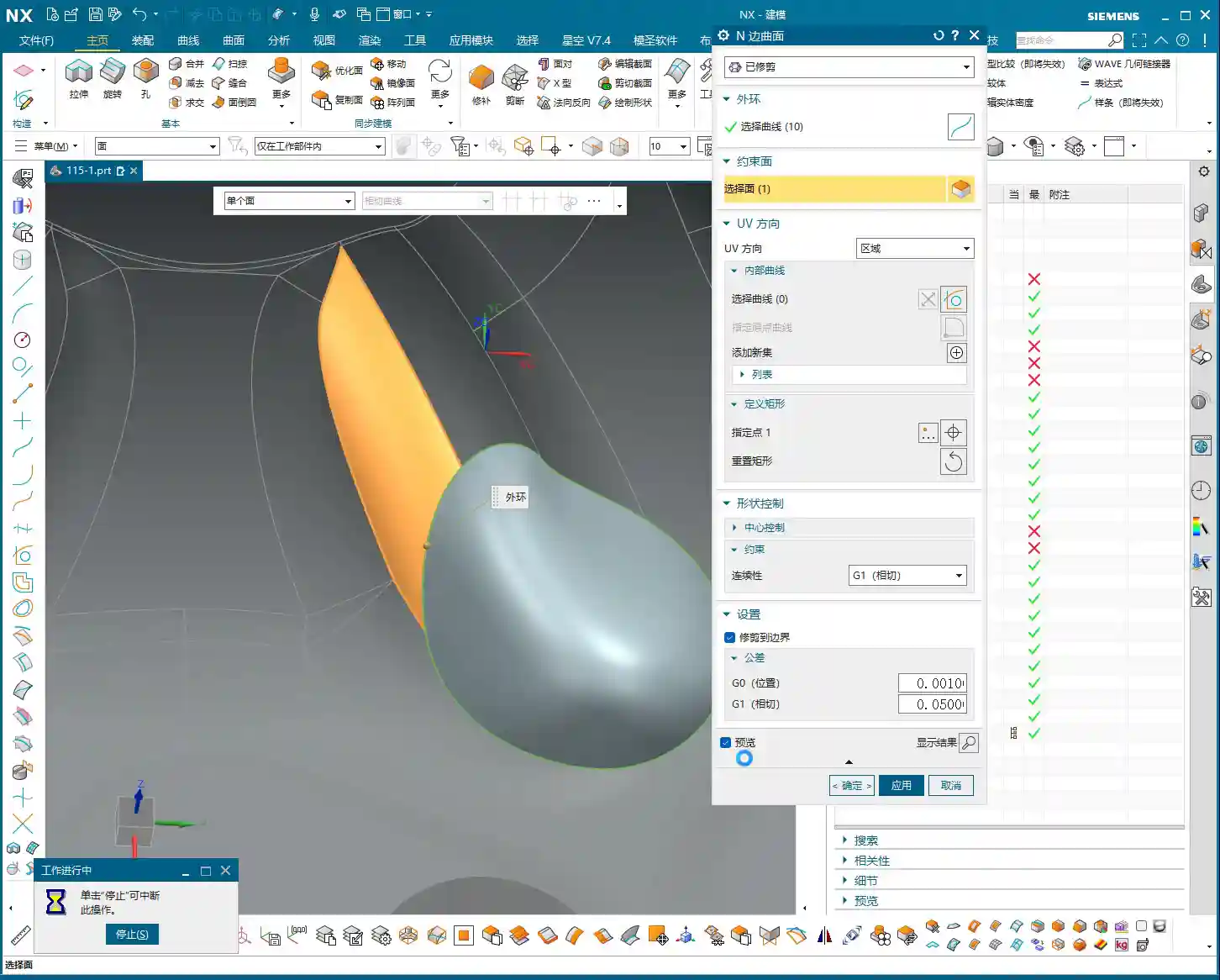
Toolpath Optimization and Pitfall Avoidance for Curved Surfaces
This part features some sloping surfaces or slightly outward-curving undercut areas. These are roughing traps!
- If you use a standard roughing toolpath directly, the tool is highly likely to overcut downwards on the sloped surface. This is a major machining taboo! At best, it affects accuracy; at worst, it causes a tool crash in an unintended area, leading to significant losses.
- In Siemens NX, we can cleverly handle this using the “Thicken” or “Replace Face” functions.
- For problematic sloping surfaces, I can selectively “Thicken” them slightly, for example, by extruding 2 mm (approx. 0.08 inch). This way, the roughing toolpath calculation will perceive this face as extended outwards, thus preventing the tool from overcutting downwards.
- Alternatively, and more directly, “Replace” the original sloped face with a planar surface. However, ensure the replacement plane effectively guides the tool and doesn’t introduce new interferences after replacement.
- The key is to ensure the tool only mills to the specified Depth of Cut during roughing, or “avoids” areas prone to issues, thereby reducing unnecessary risks.
- Don’t just rely on software simulations and assume the toolpaths are smooth; that’s only an ideal state. During actual machining, always pay attention to the cutting sparks, sound, and even machine vibrations—these are all real-time feedback.

Hole Treatment and Toolpath Generation
If the holes on the part are too small for the roughing tool, or if you don’t intend to machine them during roughing, you need to address them.
- The simplest and most effective method is to “patch” these holes. In Siemens NX’s modeling module, you can use the “Sew Surface” or “Bounded Plane” functions to close off the hole openings.
- Why patch them? Firstly, to reduce air cutting. The tool doesn’t need to traverse around or plunge into and out of the holes, significantly boosting efficiency.
- Secondly, to prevent unforeseen issues. If a large tool hovers around a hole opening, calculation errors could lead to a tool crash or unwanted tool marks on the hole walls.
- When patching surfaces, the software might lag, especially with complex models. My experience is to turn off the “Preview” function first, and then patch one face at a time. After patching, remember to constrain the patched faces properly to ensure they don’t shift and affect toolpath calculation stability.
Inspection and Verification

Toolpath Simulation and Material Removal Simulation
Once the toolpaths are programmed, don’t assume everything is fine. The most critical step is verification!
- Always perform solid simulation; it’s the most intuitive way to check. During simulation, observe every tool movement carefully, as if you were watching it by the machine.
- Pay close attention to material distribution (In-Process Workpiece (IPW) analysis). Check where there’s still too much material remaining – does it need secondary roughing? Where is there too little material – is there a risk of undercutting? Are there any overcut areas? You need to be aware of all these.
- Specifically, revisit the sloping surfaces and undercut features that were previously addressed, confirming the tool did not overcut downwards but followed our expectations.
- Simulation allows you to make mistakes in a virtual world, which is infinitely better than making them on a real, valuable workpiece.
Fine-tuning and G-code Optimization
If issues are found during simulation, adjust immediately. Don’t procrastinate; small problems can escalate into big troubles.
- Adjust cutting parameters, such as Stepover, Depth of Cut (DOC), and feed rate, to better match the tool and material.
- Optimize toolpaths to ensure smoother tool motion, avoiding unnecessary retractions and air moves.
- It might even be necessary to modify the geometry again, for example, fine-tuning the thickened face until the toolpath is perfect.
- G-code is the language of the machine. While we typically don’t edit it manually, you should understand what each line of code represents. Especially in 5-axis programming, one incorrect parameter can indeed lead to a “miss by a millimeter, miss by a thousand miles” situation.
- Our ultimate goal is: maximum machining efficiency, lowest cost, and highest part quality! This is the pinnacle we machining professionals strive for.
Summary: Pitfall Avoidance Guide
- Fillet Radius Dictates Tool Selection: The smallest fillet radius on the part is crucial for selecting the roughing tool’s radius. Remember, the roughing tool’s corner radius must be smaller than the part’s smallest fillet radius to leave appropriate machining stock in the corners.
- Sloping/Undercut Surfaces are Traps: For these special contoured surfaces, remember to use Siemens NX’s “Thicken” or “Replace Face” functions for optimized processing. This is a crucial technique to prevent the tool from overcutting downwards and avoiding overcut conditions.
- Holes Require Patching: Patching holes before roughing effectively prevents air cuts and improves machining efficiency. If you experience lag when patching, try turning off the preview, performing the operation step-by-step, and ensuring faces and edges are properly constrained.
- Simulation is the Litmus Test: After toolpath generation, comprehensive solid simulation and IPW analysis are mandatory. Focus on checking material distribution to ensure no undercuts or overcuts, identifying and resolving issues early.
- Practical Experience Trumps Theory: Don’t just stare at software simulations; combine them with actual machining experience to judge if the toolpath is reasonable. Cutting sparks, sound, and vibrations are all crucial feedback signals—what you can’t learn from books is found here.
- Ample Stock Allowance is Essential: Ensure sufficient stock dimensions, especially in the Z-axis direction. This is fundamental for safe clamping and smooth progression of subsequent operations.
👤 About the Author:
The author is a veteran CNC machining professional with 15 years of industry experience, specializing in UG NX programming. This article is an original work representing personal practical insights.
⚠️ Copyright Notice: Unauthorized reproduction or distribution without prior communication is strictly prohibited.
Leave a Reply