📝 Key Takeaways: Master Wang provides a hands-on tutorial for setting cutting parameter strategies and stock in UG NX 1980. Learn how to select cutting directions, control undercut, and precisely manage various stock allowances to avoid common mistakes and improve efficiency and accuracy in real-world machining.
Hello everyone, I’m Master Wang. Let’s pick up where we left off. Once we cover this section today, we’ll have basically wrapped up this page of work.
Cutting Strategy: More Than Just Direction
Let’s open up Cutting Parameters. There are quite a few commands in here, so we need to break them down one by one. First, let’s look at the ‘Strategy’ section.
Cutting Direction: Climb vs. Conventional Milling, Different Jobs
Initially, you’ll see a cutting direction, mainly referring to the Cutting Angle. When it’s moving in the negative direction, this cutting angle appears. It’s actually quite simple: it’s either climb milling (順銑) or conventional milling (逆銑).
Typically, we mostly choose climb milling. We rarely opt for conventional milling. However, in special working conditions, conventional milling does have its place. Just remember these two methods; climb milling is generally sufficient.
Automatic Cutting Angle: The Software’s ‘Cleverness’
Have you ever noticed that at the beginning of a program, the tool always starts cutting from a specific direction, then follows a certain path? For instance, why does it always start cutting from this direction, and not the opposite? This is the result of automatic control of the cutting angle.
Click it, and you’ll see a bunch of options like ‘Specify’, ‘Longest Edge’, ‘Fixed Vector’, ‘Receive Vector’. Don’t panic, we’ll start with the most commonly used ones.
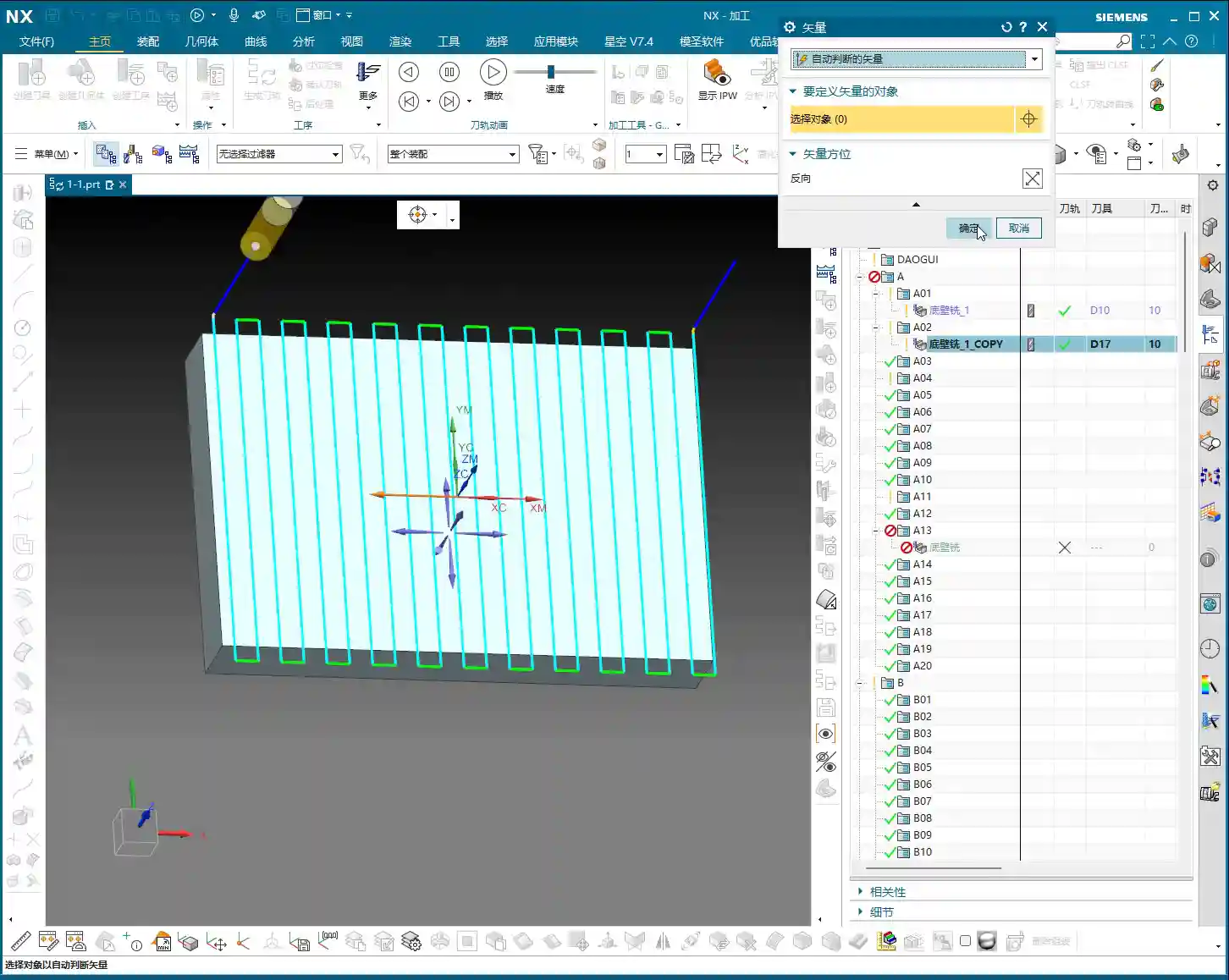
For example, choose Fixed Vector (Specify Vector). Click it, and you’ll see four directional arrows on the part. Click on any directional arrow, say this one, then ‘Specify’, and generate the toolpath. You’ll notice:
- If you select a vertical arrow, the tool will perform vertical machining.
- If you select a horizontal arrow, the tool will perform horizontal machining.
In short, this command is used to change the machining direction, whether it’s milling horizontally or vertically, you decide. If you deselect the specified vector, it will revert to automatic determination.
Specify Angle: Fine Control for Multi-Axis Machining
Let’s look at ‘Angle’ within ‘Specify’. When the angle is 0 degrees, the toolpath is horizontal. If we change the angle to 90 degrees, and look at the arrow, it’s clearly pointing upwards, and the tool will machine vertically.
This function simply allows you to change the tool’s machining direction. You can also try 45 degrees, which can also machine, but in actual work, we rarely use such diagonal machining methods; most of the time, it’s either horizontal or vertical.
So, the meaning of ‘Cutting Angle’ is to let you control the tool’s path. Those parameters we didn’t cover are generally less used in face milling, and in most cases, automatic mode is sufficient.
Add Finishing Pass: A ‘Redundant’ Feature for Face Milling
The ‘Add Finishing Pass’ option below is generally not very useful for face milling. We can ignore it for now.
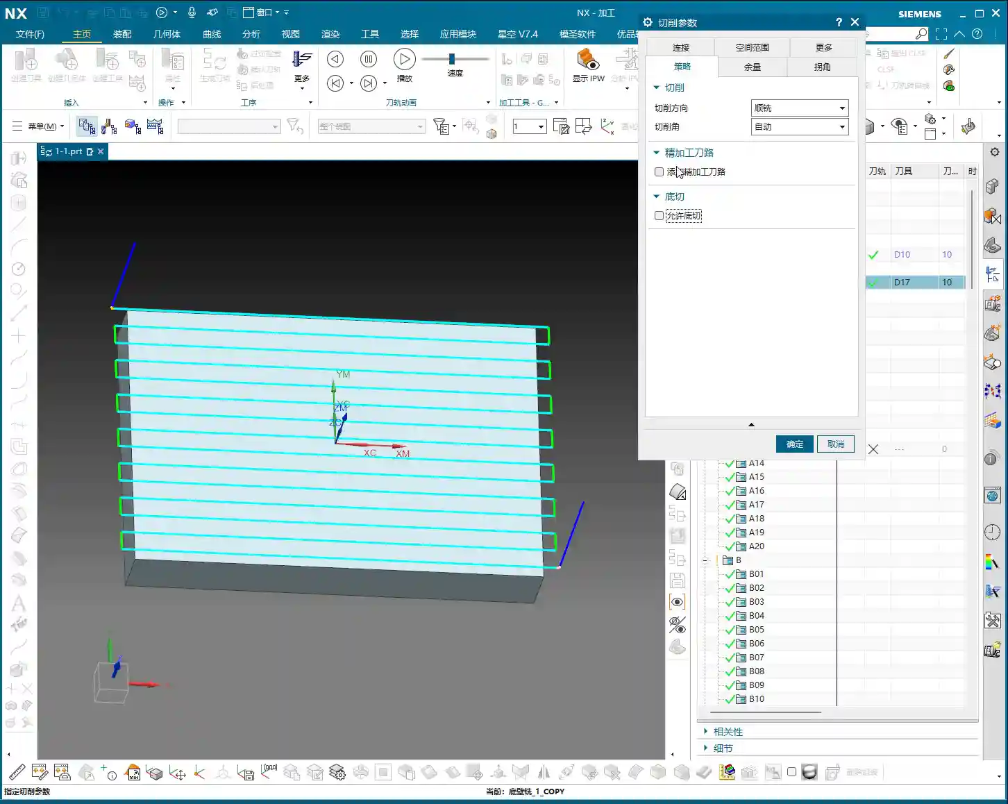
Allow Undercut: A ‘Sharp Tool’ for Deep Cavities
Here’s an important one! As soon as you turn on ‘Allow Undercut’, you’ll see the effect. Look at this small icon: the first pass is fine, but what about the second?
Did you notice that it has overcut, milling away the entire side wall? This is the function of ‘Allow Undercut’; it enables the tool to machine into internal corners of a part, even cutting into areas smaller than the tool’s diameter.
If you don’t allow undercut, it will only follow the largest outer contour, unable to reach deeper or narrower areas. Of course, if you’re using a special tool like a T-slot cutter, allowing undercut for machining side walls is perfectly fine.
However, typically, to avoid unnecessary overcutting, we do not enable ‘Allow Undercut’ unless you have specific machining requirements, such as machining undercuts or reverse angle slots.
Cutting Mode and Toolpath Direction: Choosing Your Strategy
When we change the ‘Strategy’ to ‘Follow Part’, you’ll notice the Cutting Angle option disappears. Why? Because it doesn’t involve whether you’re machining horizontally or vertically, so naturally, this option isn’t there; only ‘Climb’ and ‘Conventional’ directions remain.
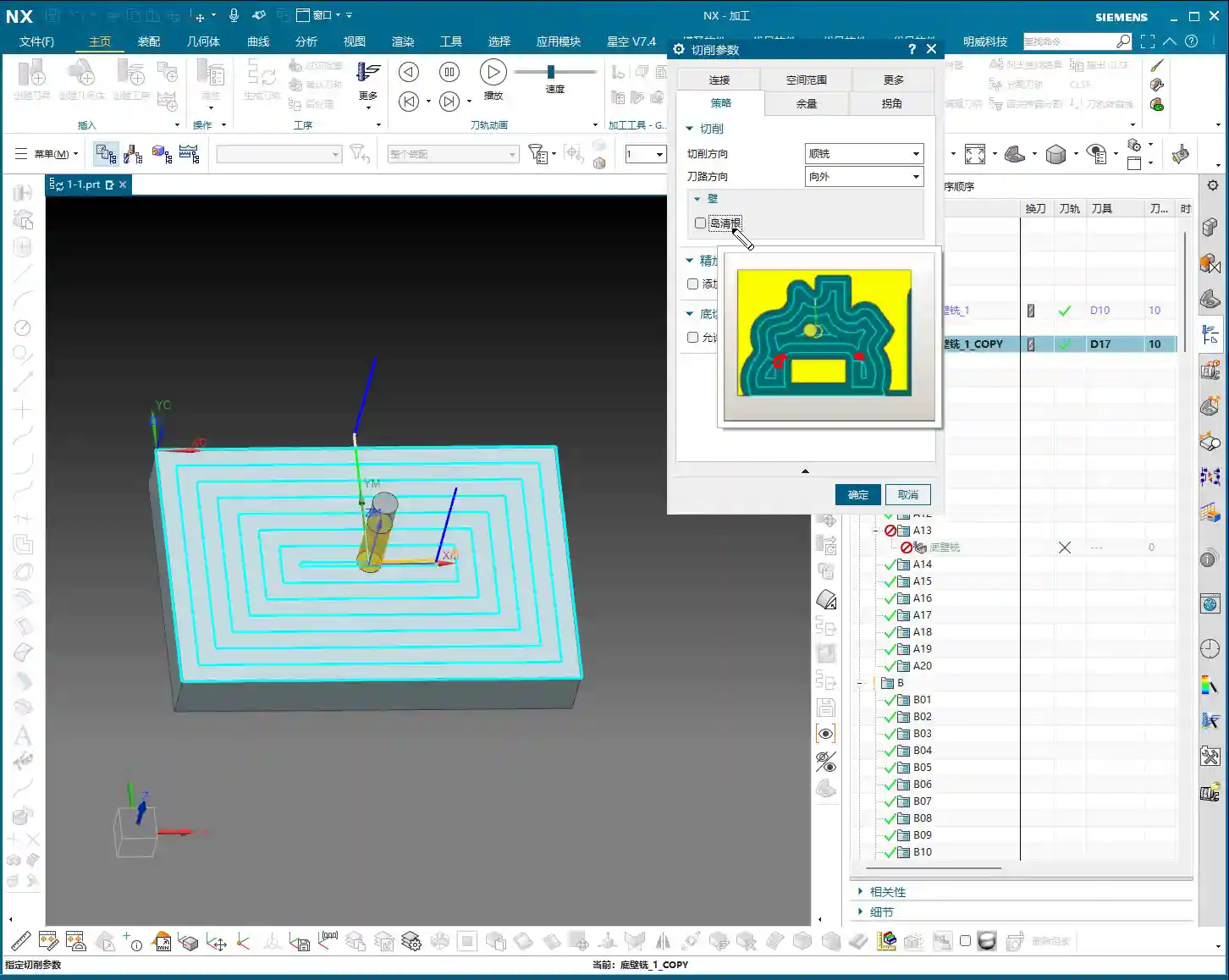
This teaches us a principle: the ‘Strategy’ is determined by the ‘Cutting Mode’ we select. For example, if we change to ‘Follow Periphery’ and generate the toolpath again, you’ll find an additional option: ‘Inward’ or ‘Outward’.
- Inward: The tool machines from outside to inside, gradually moving inwards.
- Outward: The tool machines from inside to outside, clearly moving diagonally outwards.
Therefore, when you choose ‘Follow Periphery’, you can flexibly select ‘Inward’ or ‘Outward’ toolpath directions.
Option B: The Secret Weapon for Corner Cleanup
In ‘Follow Periphery’ mode, an additional Option B will appear. What does this B mean? Typically, if you check it, you’ll find that the toolpath includes some ‘corner cleanup toolpaths’.
Especially when machining certain corners, if your Corner Cleanup (Option B) is not enabled, you might find that some areas are not machined. In this case, enabling it can resolve the issue.
However, if your machining is simply basic face milling and doesn’t require corner cleanup, there’s no need to enable Option B.
Stock Settings: Key to Accuracy and Efficiency
Now that we’ve covered strategy, let’s move on to ‘Stock’. This is crucial for part accuracy and machining efficiency!
There’s ‘Part Stock’, ‘B Stock’, ‘Floor Stock’, ‘Blank Stock’, ‘Touch Point Stock’, ‘Inner Tolerance’, ‘Outer Tolerance’, and so on. Let’s go through them one by one.
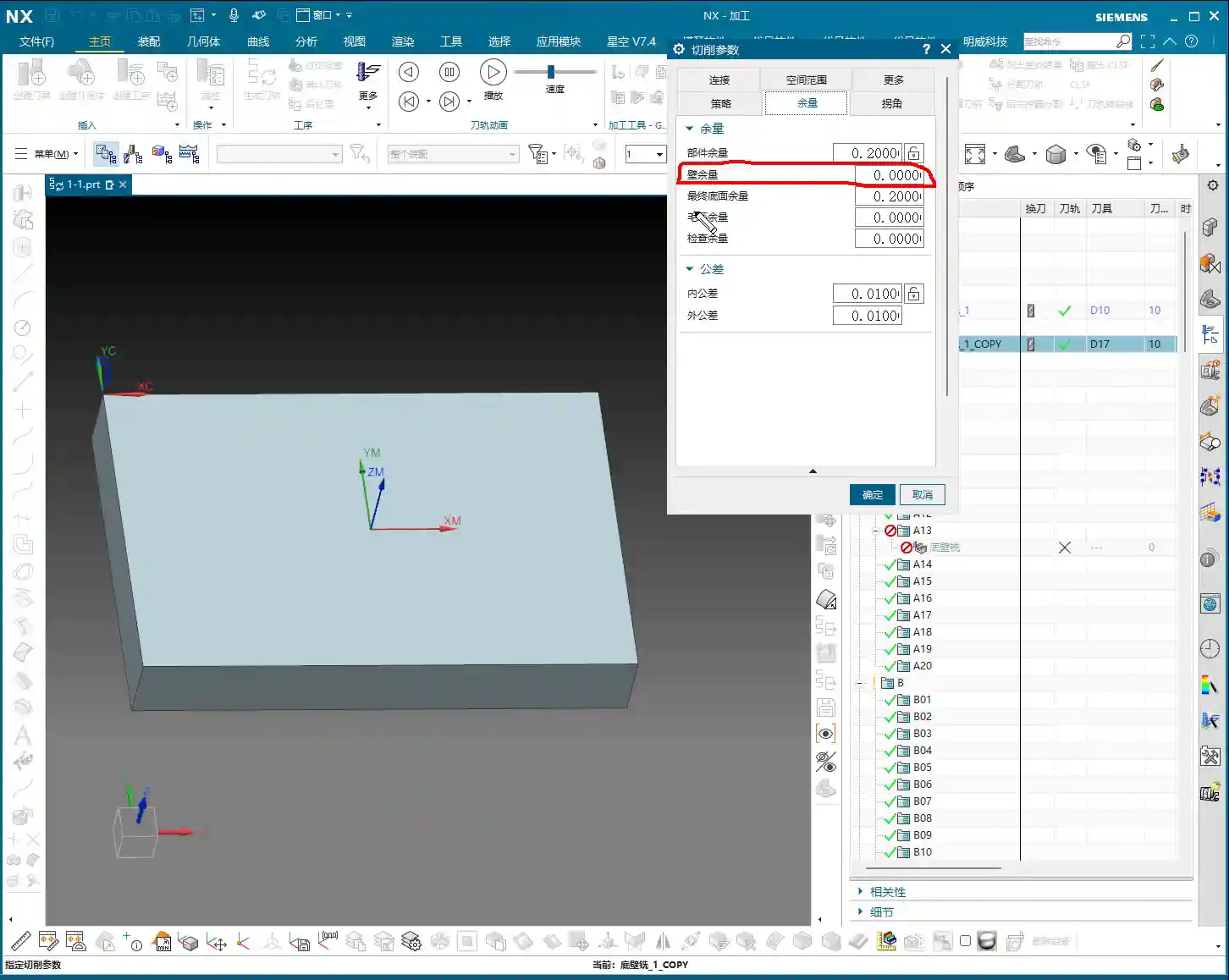
Part Stock: How Much to Leave on Side Walls?
‘Part Stock’ is simply how much stock we leave on the side walls of the specified part. Look at this image, the blue side wall. If we change the Part Stock to 0.2mm, it means we’ve left 0.2mm of stock on the side wall.
This is crucial during roughing to leave some material for the finishing pass, preventing insufficient accuracy or excessive tool wear from trying to finish in one go.
B Stock: Dedicated Stock for Special Features
‘B Stock’ refers to the stock left for the specified B entity. Since we haven’t selected a B entity yet, this B Stock is currently unused and remains 0. We typically don’t use B entities for machining, so we can skip this for now.
Floor Stock: How Much to Leave on the Bottom?
The stock for the ‘Specify Final Floor’, this one is quite easy to understand. For instance, set it to 0.2mm.
Let’s replay the toolpath and then measure. See, the distance between the machined surface and our specified floor is clearly 0.2mm. This is the Floor Stock.
In practical work, you don’t need to measure every time. Once you’ve set it correctly and you see that stock is clearly left, then it’s accurate. This relates to our Percentage of Tool parameters; if the percentage is not set reasonably, the toolpath will appear very dense.
Summary: Strategy and Stock are Interconnected
We’ve pretty much covered the ‘Strategy’ and ‘Stock’ pages in the cutting parameters. The remaining commands, like ‘Connect Mold Toolpath’, are less used in face milling, so we can skip them for now.
Remember one thing: all these strategy and stock settings must be flexibly adjusted according to your actual workpiece, material, and machining requirements. There are no one-size-fits-all parameters, only the most suitable configuration for the current task.
Summary: Pitfall Guide
- Cutting Direction: Mostly climb milling, conventional milling for special cases, but be cautious to avoid chatter.
- Cutting Angle: Adjust toolpath direction based on whether the machining surface is horizontal or vertical, to improve efficiency.
- Allow Undercut: Only enable when machining deep cavities or undercuts; otherwise, use sparingly to prevent overcutting.
- Strategy and Cutting Mode: Strategy options change with the cutting mode; understand their interrelationship.
- Option B (Corner Cleanup): Only enable when corner cleanup is needed, to avoid unnecessary calculations and toolpaths.
- Part/Floor Stock: Set precisely according to roughing and finishing requirements to ensure smooth subsequent operations and avoid undercutting or overcutting.
- Coordinate System: MCS (Machine Coordinate System) is the datum; WCS (Work Coordinate System) can be placed anywhere without affecting machining.
- Parameter Fine-tuning: In actual machining, parameters may need fine-tuning based on machine status, tool wear, etc. Don’t just rely on software simulation; watch the cutting sparks and observe the actual results!
Leave a Reply