📝 Key Takeaways: ** Master Wang personally reveals real-world secrets of Siemens NX Deep Profile Helical Milling! From face selection to helical plunging, discover how to achieve efficient Corner Cleanup, eliminate residual material at the bottom, optimize Stepdown and residual material, effortlessly tackling complex Contour Milling challenges like fillets and chamfers. Practical tips you won’t find in textbooks will help you boost machining efficiency, avoid common machining pitfalls, and master 0.005mm-level precision control. **
Hello everyone, I’m Master Wang. Today, we’ll continue discussing the machining module in NX (Siemens NX), especially this **Deep Profile Helical Milling** operation. Listen up, this isn’t just about clicking a few buttons in the software interface; there’s a lot more to it!
What is Deep Profile Helical Milling? Listen to me explain!
You guys have probably used “Profile Helical Milling” before, right? With that, you select an edge or a profile curve, and it plunges along that curve, drawing a yellow helical line downwards. It’s fine for open shapes or simple holes. But this **”Deep Profile Helical Milling”** we’re talking about today, it’s different.
Simply put, it focuses more on **selecting “faces” to define the machining area**, especially for enclosed areas with vertical walls. It can recognize the solid faces you select and then perform helical plunging. This approach is much more effective and hassle-free for machining deep cavities or when precise control of side walls is required during Roughing, compared to simple Profile Helical Milling.
Face Selection Secret: Bid Farewell to the “Sketching Lines” Era
Listen up, this is the first key point! In “Deep Profile Helical Milling,” you don’t select lines; you select **vertical “wall faces”** (that is, faces perpendicular to the bottom surface). See, when you choose this function, it prompts you to select faces, and you should select the side wall faces that need to be machined. Don’t foolishly select a line; that would be no different from regular Profile Helical Milling and would limit your toolpath flexibility.
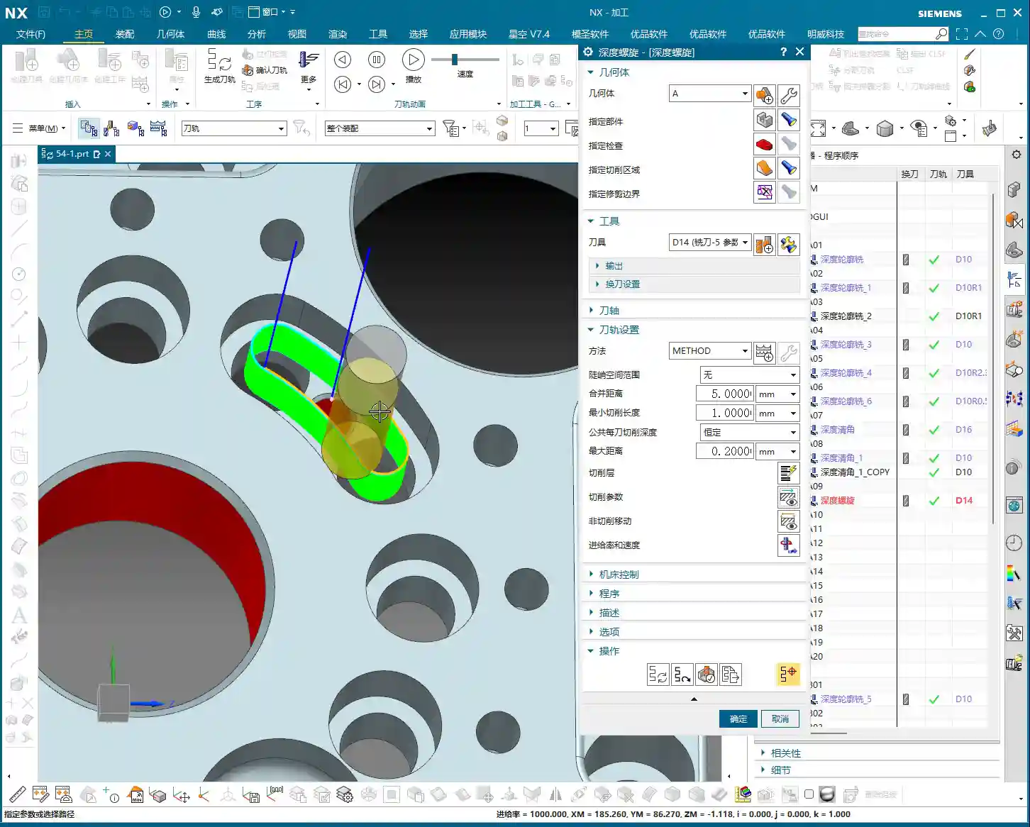
Once you select the faces, the software understands that the area is enclosed. It will automatically plan a top-to-bottom, spiraling toolpath based on your set parameters to clear the entire region. This efficiency is much higher than tracing lines one face at a time, especially for irregularly shaped deep cavities, saving you a lot of manual line selection hassle.

The Secret to Helical Plunging: The Key is “Ramp Angle”
Want the tool to truly “helix” down instead of plunging in “stair-step” segments? There’s a crucial setting here: in the “Connect” tab, find **“Ramp Along Part”**. You need to check this! Then, set the **“Ramp Angle”** below it to 0 degrees. Yes, you heard that right, 0 degrees!
Why 0 degrees? Because we want it to smoothly helix down along the specified face, like a drill, rather than having an angled plunge. Setting it to 0 degrees allows the tool to completely follow the side wall downwards, avoiding impact and reducing the risk of Chatter and Tool deflection. This benefits both tool life and surface quality. This is a practical tip that textbooks might not emphasize!
Efficiency and Precision: The Balance of Stepdown and Residual Material

Stepdown Settings: Balancing Calculation Speed and Machining Quality
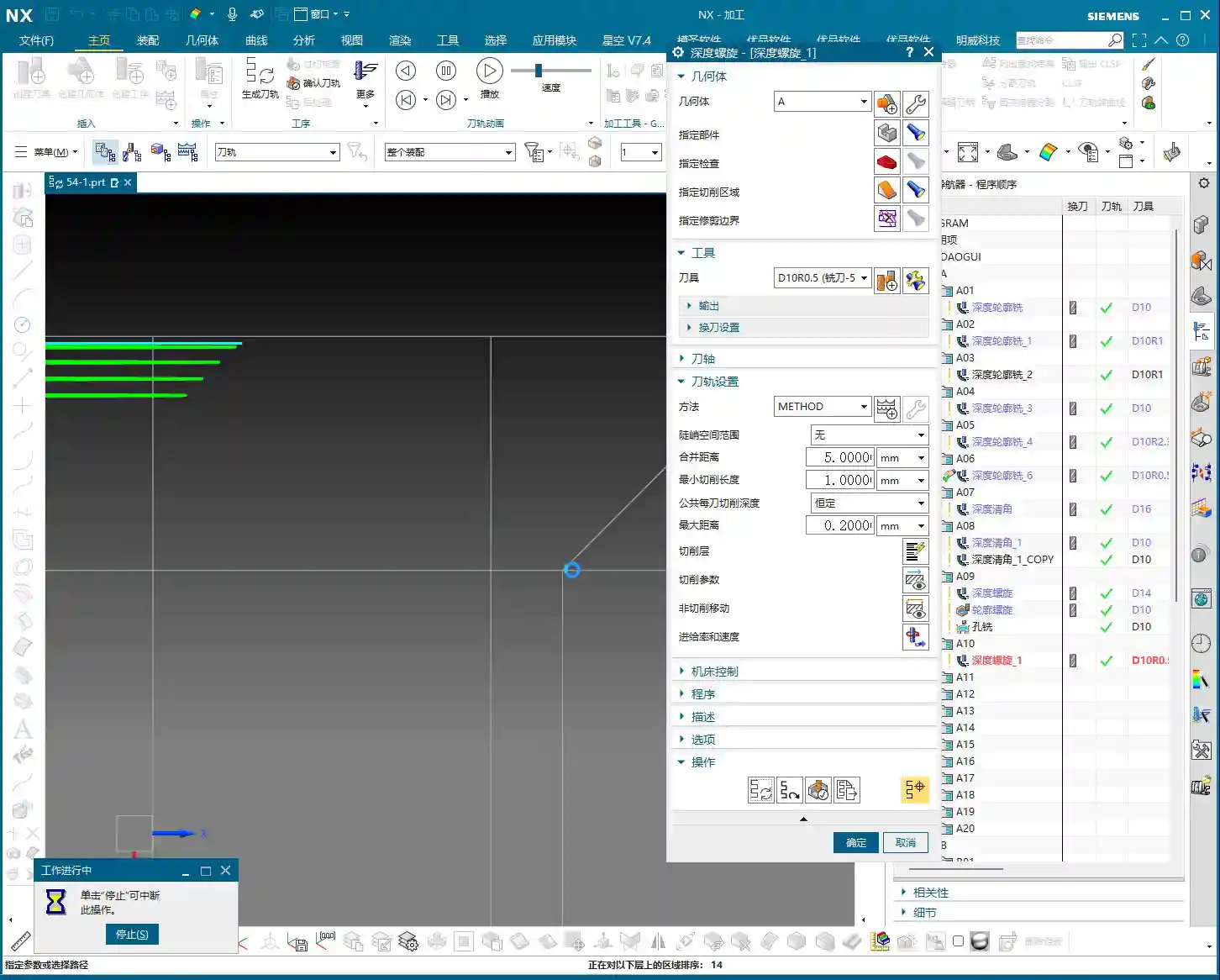
When setting the **Stepdown** (which is the depth of cut for each pass), there’s a little trick. If you’re just quickly verifying the toolpath or running a simulation on your computer, you can set a larger Stepdown, for example, 5 mm. This speeds up program calculation, and you’ll see the results quickly. But listen up, this is just for “getting a general idea”!
However, when it comes to actual machine tool machining, especially during Roughing, the Stepdown can’t be set so casually. You need to determine it based on material hardness, tool diameter, and machine rigidity. For instance, machining titanium alloy and common aluminum will definitely require different Stepdown values. For typical Roughing, we might set it between 0.2 mm and 1 mm. A Stepdown that’s too large can lead to Tool deflection, while one that’s too small is too time-consuming. **Don’t just rely on software simulation; observe the cutting sparks!** Stable, normally colored sparks indicate that your parameters are set correctly.
Residual Material Control: A Critical Step for Finishing
**Residual Material** (also known as “stock to leave for the next operation”). During the Roughing phase, a certain amount of residual material is typically left, for example, 0.3 to 0.5 mm, to be removed during the Finishing pass. However, if the current operation is the final Finishing pass, then remember to set the residual material to 0. Setting it to 0 allows the tool to mill away all excess material, achieving the dimensions required by your drawing.
Especially when pursuing high precision like ±0.005mm, residual material control is crucial. Not an iota can be overlooked. If you find that the machined dimensions consistently deviate, the first thing to check is your residual material settings, as well as the machine tool’s accuracy compensation.

Deep Profile Helical Milling vs. Other Machining Strategies
Comparing with Profile Helical Milling: Where’s the Advantage?
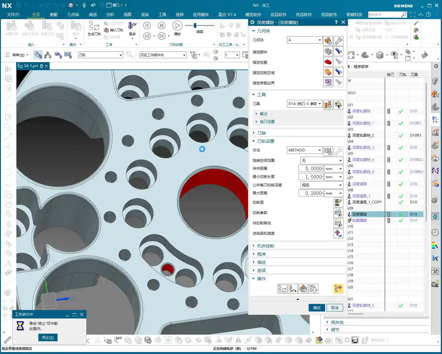
As mentioned before, “Profile Helical Milling” primarily involves selecting lines; it only knows to follow the lines you’ve chosen. But “Deep Profile Helical Milling” involves selecting faces, allowing it to recognize the entire enclosed area. So, if you have multiple holes or several similarly shaped deep cavities to machine, by directly selecting multiple faces with “Deep Profile Helical Milling,” it can automatically plan the toolpaths for you, **saving you the hassle of selecting lines and stitching them together one by one**. Moreover, it performs more stably and generates more continuous toolpaths when dealing with complex surfaces and varying cross-sections.

Comparing with Hole Milling: A Victory for Flexibility
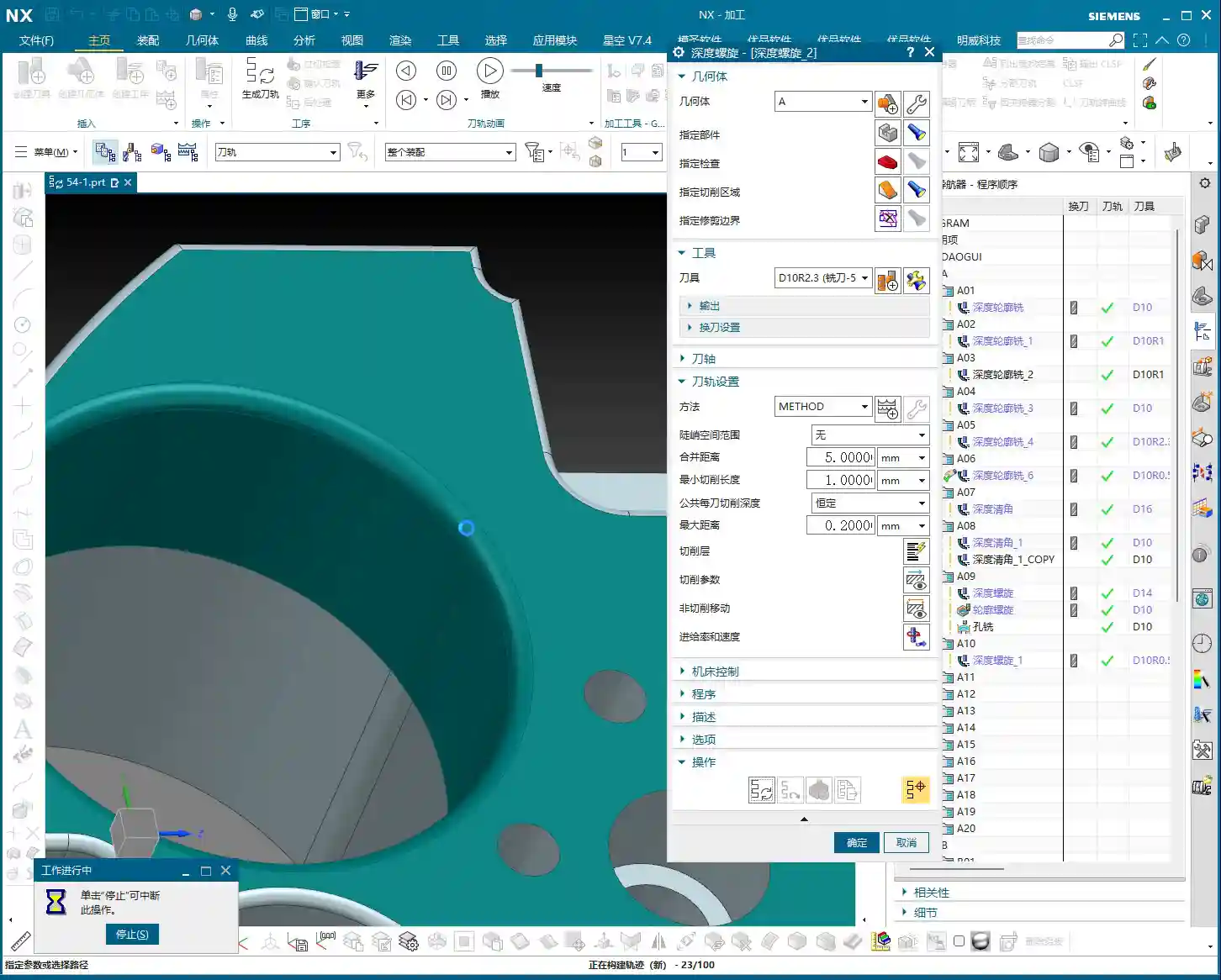
Surely some apprentices will ask: “Master Wang, isn’t this just drilling holes? Can’t we just use ‘Hole Milling’?” Well, for simple circular holes, “Hole Milling” is indeed more direct and efficient. However, if this “hole” isn’t a regular circular hole, or if it features chamfers, fillets, or even an irregular shape, then “Hole Milling” won’t be sufficient.
This is where the advantage of “Deep Profile Helical Milling” shines. It can perform helical machining along your selected irregular faces, **perfectly adapting to various complex hole and cavity shapes**. It’s like having two tools in your hand: a standard kitchen knife and a Swiss Army knife. When encountering complex situations, the Swiss Army knife is clearly more flexible and effective. For us in machining, it’s about learning to choose the most suitable machining strategy based on the part’s characteristics—that’s how you get the job done, and done well!
Troubleshooting: Chamfers, Fillets, and Bottom Residual Material
Chamfer and Fillet Machining: One Tool Does It All!
Many times, parts not only have holes but also require chamfers (C-angles) or fillets (R-angles). For example, if the drawing calls for a C1 chamfer or an R0.5 fillet, with “Deep Profile Helical Milling,” you simply select the corresponding chamfer face or fillet face. Then, choose an appropriate tool—such as an R0.5 ball nose end mill or a chamfer tool—and it will machine these intricate features for you along a helical path. This is much more time and effort-efficient than using several different operations to handle these details, and the toolpaths are smoother.
Bottom Corner Cleanup: How to Avoid “Leftovers”
This is an old problem, and many novices often make this mistake. When you use a bull nose end mill or a ball nose end mill to machine the bottom of a deep cavity, due to the tool’s radius, it often cannot completely clear the residual material in the bottom corners, always leaving a little “root,” or a small triangular remnant. Don’t be fooled by software simulations; once you machine it on the machine, you’ll find there’s residual material.
The solution is simple: in your program, find the **“Part Stock”** or **“Extension”** option and extend the toolpath downwards a bit. For example, extend it by 2.5 mm, or directly by **50% of the tool diameter**. This way, the tool’s radius can reach the very bottom, thoroughly clearing away those pesky residual materials. This is about “knowing not just what to do, but why to do it”—don’t just look at the surface; pay attention to the details.
Summary: Pitfall Avoidance Guide
- Select Faces, Not Lines: When using “Deep Profile Helical Milling,” always select the correct vertical wall faces, not contour lines; this greatly simplifies programming.
- Core Helical Plunging Setting: In “Connect,” check “Ramp Along Part” and set the “Ramp Angle” to 0 degrees to ensure smooth helical plunging and avoid Tool deflection.
- Set Stepdown Appropriately: For simulation, you can set it larger to speed up calculation. For actual machining, adjust it to 0.2mm~1mm based on material, tool, and machine rigidity to ensure stable cutting and normal sparks.
- Zero Residual Material for Finishing: If the current operation is a Finishing pass, ensure “Residual Material” is set to 0 to meet precise dimensional requirements.
- Extend for Bottom Corner Cleanup: When machining deep cavity bottoms with an R-radius tool, extend the toolpath downwards by 2.5mm or **50% of the tool diameter** in the toolpath settings to thoroughly remove bottom residual material.
- Match Tool to Feature: When machining chamfers or fillets, select a matching tool (e.g., R-radius tool, chamfer tool) to achieve a single-pass formation.
- Don’t Blindly Trust Software Simulation: Simulation is only a reference; ultimately, you must observe the actual cutting effect, sparks, and chips, and adjust based on experience.
Remember these points, and you’ll avoid many detours in Siemens NX Deep Profile Helical Milling. Your programs will be not only efficient but also produce high-precision parts. In today’s fiercely competitive industrial product market, the ability to manually produce high-precision, high-quality parts is your greatest competitive advantage!
👤 About the Author:
The author is a veteran CNC machining professional with 15 years of industry experience, specializing in UG NX programming. This article is an original work representing personal practical insights.
⚠️ Copyright Notice: Unauthorized reproduction or distribution without prior communication is strictly prohibited.
Leave a Reply