📝 Key Takeaways: Master Wang meticulously breaks down the entire Siemens NX part machining process, from workpiece analysis and precise tool selection to roughing and finishing strategies. The focus is on efficiently programming toolpaths and avoiding overcutting. Combining practical experience with NX techniques, he reveals beyond-the-textbook tricks to ensure both precision and efficiency, saving you from common pitfalls!
Hello everyone, Master Wang here. Today, let’s cut the fluff and dive straight into the practical insights. We’ll take this part and break down the real-world tricks in NX programming—those things that look simple but often lead to problems in practice.
Part Analysis and Machining Strategy: A Solid Foundation is Key
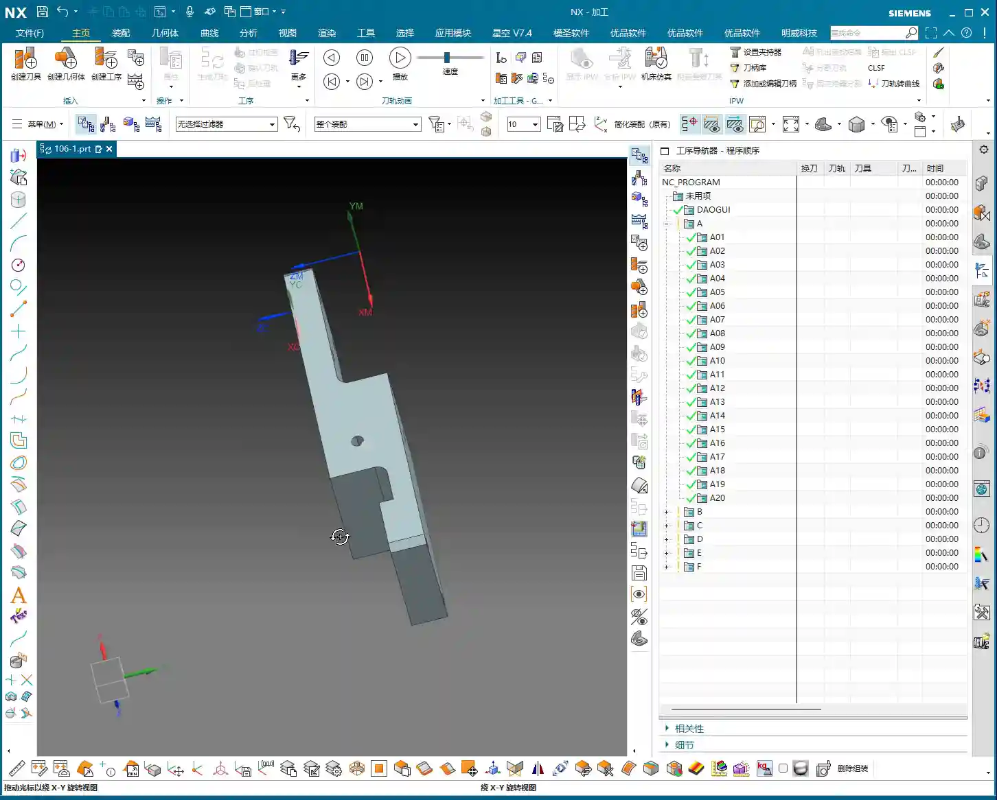
Listen up: When you get a new part, what’s the first thing you look at? Its overall structure. For this piece, both the front and back faces are primary machining areas. The side walls have a few holes, but we’ll get to those later. Don’t rush into it; let’s first figure out a general machining strategy.
Stock Definition and Coordinate System Placement
First, your workpiece needs stock, right? In NX, we need to define a Bounding Box for it. Simply input “0” to automatically generate a clean rectangular block. This serves as our starting point for machining; all toolpaths will revolve around it. Then, don’t place your Work Coordinate System (WCS) haphazardly; position it directly at the geometric center of the stock. This way, whether you flip the part or re-fixture, you’ll always have a reliable reference, ensuring peace of mind and stable operation.

Overall Machining Strategy: Large Features First, Then Small; Roughing First, Then Finishing
For this part, we’ll first machine the front face, face milling it flat and smooth, then flip it over to machine the back. As for the side holes and smaller features, we’ll tackle those separately once the major faces are done. Why this approach? Because the major faces serve as datums; if the datum is unstable, all subsequent finishing will be wasted. As we often say in the shop, “a weak foundation will crumble the whole structure,” and the same principle applies to machining.
The Art of Tool Selection: Beyond Size, Focus on Functionality
Tool selection is a science; you can’t just pick any tool. While NX offers various analysis tools, you still need to make judgments based on the actual material and machine conditions.

Draft Analysis and Workpiece Characteristics
NX has a “Draft Analysis” function that lets you quickly see if a part’s surfaces are flat and straight, or if there are any steep sloped faces. Looking at this part, most of it consists of straight and flat surfaces, with no complex slopes or curved surfaces. This tells us that a flat end mill or a corner radius end mill will handle most of the job; we won’t need any fancy ball end mills or tapered end mills.
Carefully Selecting Tool Combinations Based on Features
- Roughing Large Faces: For efficiency, we need a large tool. I’ve looked it over, and we can use a Ø63mm, R0.8 roughing end mill or a flat bottom end mill with a corner radius (bull nose). Why Ø63mm? Given the part’s dimensions, using it for roughing will save a lot of tool change time, and we can also use a larger Stepover.
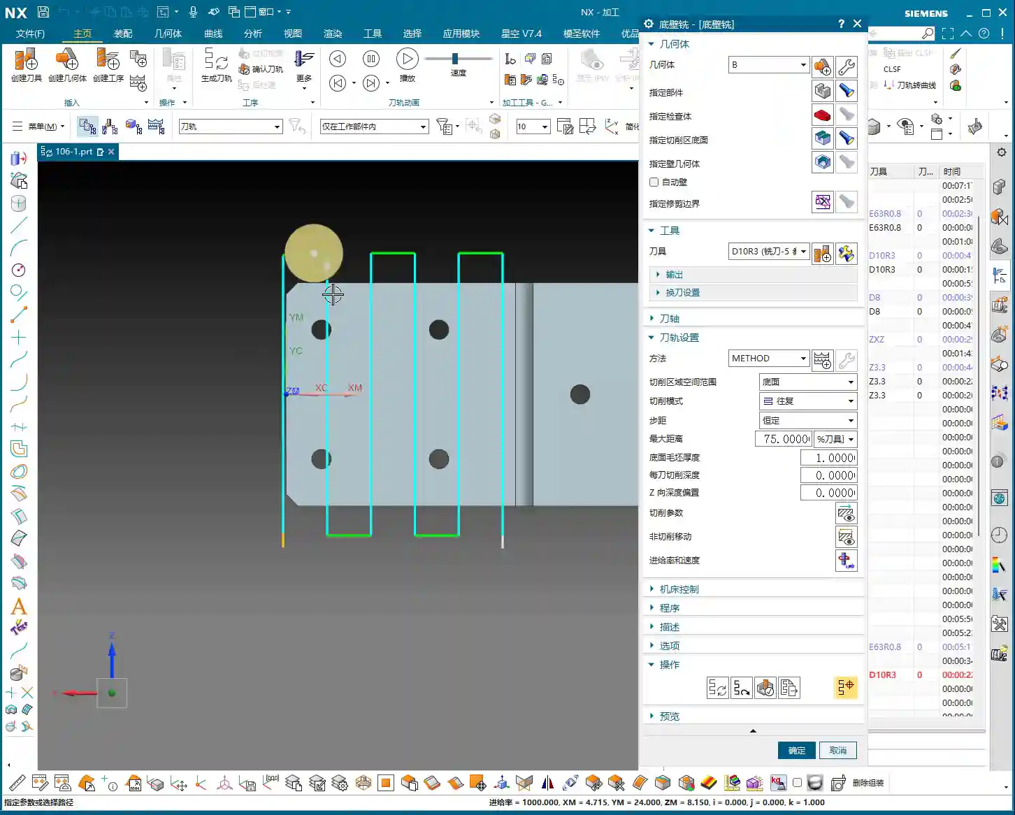
- Side Walls with R3 Fillets: Some side walls of the part have R3 fillets. For these areas, you’ll need the corresponding Ø12mm, R3 ball end mill or a bull nose end mill. NX will help you identify these, but you need to be aware—don’t try to force a flat end mill to machine an R-angle; that will damage the tool or workpiece!
- Side Walls without Fillets and Corner Cleanup: The other side walls have no fillets, and some areas feature 9mm narrow slots or require Corner Cleanup. This is where a Ø8mm flat end mill comes in handy; it can clean up those corners that the R3 tool can’t reach. Note that even though there’s a 9mm feature here, using the Ø12mm R3 for roughing, with proper toolpath control, will prevent overcutting. Then, use the Ø8mm tool for finishing passes. This is what we call “Rough with a large tool, finish with a small one.”
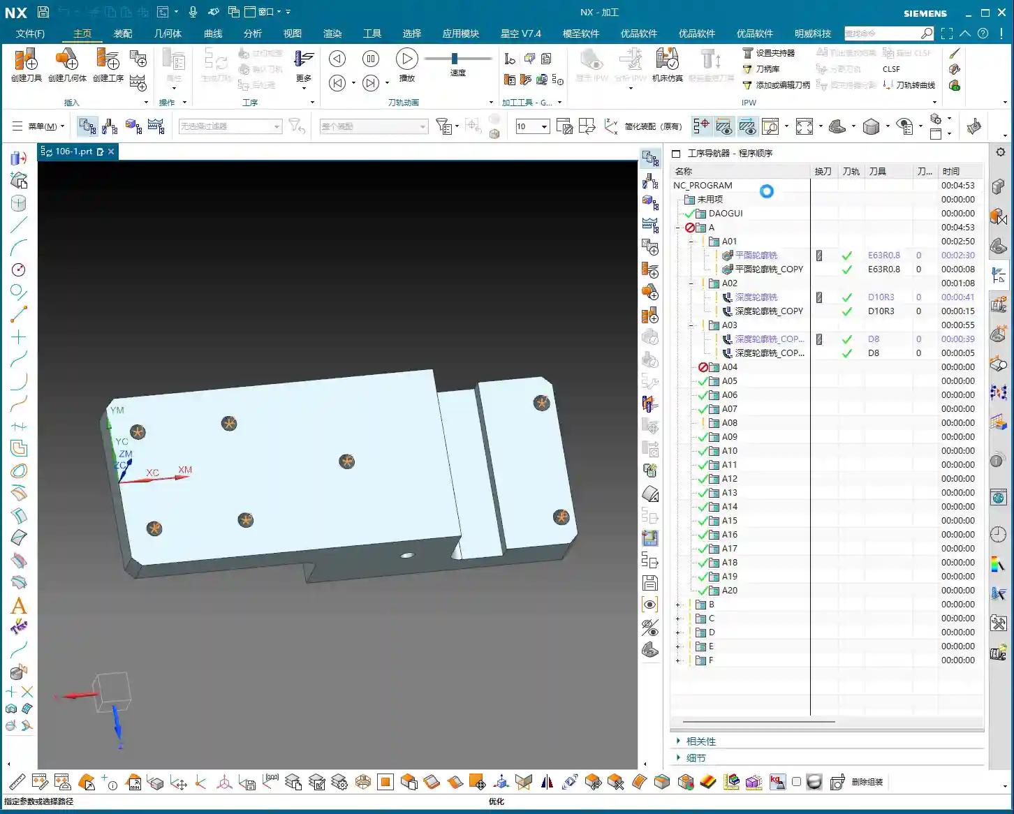
- Hole Machining: As for the 3.3mm holes, they look like pilot holes for tapping. Typically, we’d just drill them with the corresponding drill bit; they’re not the focus of milling, so we’ll set them aside for now.
Roughing and Finishing: Practical Siemens NX Programming

Now, let’s program the toolpaths step-by-step. I’ll explain, and you take notes; these are all insights gained directly from the shop floor.
Step One: Roughing the Large Flat Face (Open Area Milling)
First, select “Open Area Milling.” Since this face is open, it allows for more flexible toolpath planning.
- Tool: We’ll use the Ø63mm, R0.8 tool we just discussed.
- Stepdown: Set the Stepdown to 0.5mm. Don’t get greedy; keep the cutting load stable, especially for new parts—always start conservatively.
- Stock: Leave a 0.2mm stock allowance on both the side walls and the bottom face. This is reserved for finishing, because “Leave enough stock, and finishing will be stress-free.”
- Engage/Retract: Change the Engage/Retract method to “Linear”, and set the percentage to 55%. This ensures smoother entry and exit, reducing tool impact.
- Retract Height: Since it’s an open area, set the retract height directly to 0. This saves non-cutting time.
Generate the toolpath. See how smooth it looks? A large tool moving back and forth, highly efficient. But don’t just rely on software simulation; you need to envision what the sparks look like during cutting and if the sound is right.
Step Two: Finishing the Large Flat Face (Stock Removal)
Once roughing is complete, next is finishing. Simply copy and paste the roughing program you just created, then modify the parameters:
- Stock: Change the stock allowance on both side walls and the bottom face to 0.
- Cutting Method: Change “Mixed Milling” to “Climb Milling.” Pay close attention here: for finishing, using climb milling results in more stable cutting and a better surface finish. This is practical experience that textbooks might not emphasize as much.
Generate it again, and this face will be smooth and shiny. “A mirror-like finish is the mark of true craftsmanship!”

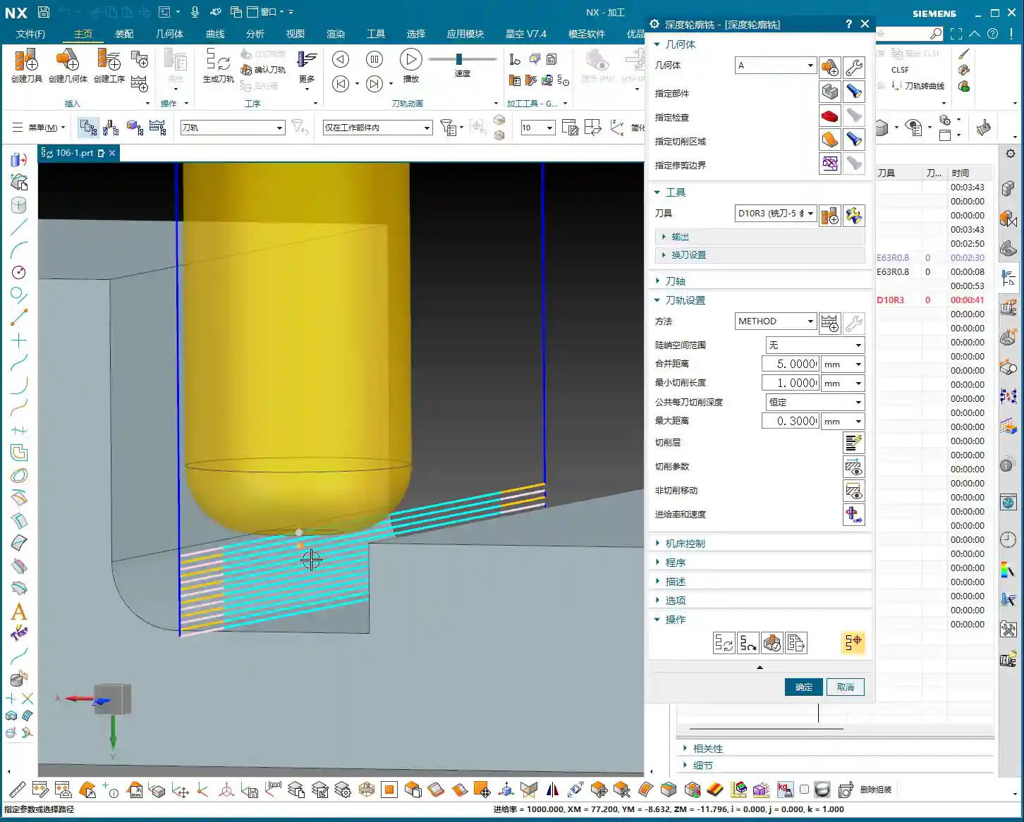
Step Three: Finishing R3 Fillets on Side Walls (Depth Profile Milling)
For these R3 side walls, we need to use “Depth Profile Milling.”
- Tool: Use the Ø12mm, R3 tool.
- Stepdown: Set the Stepdown to 0.3mm. It’s a finishing pass, so go slow and steady.
- Machining Depth: Control the machining depth carefully, going 4mm down from the top face.
- Stock: Leave 0.2mm on the side walls and 0.15mm on the bottom face.
【CRITICAL REMINDER! PITFALL AVOIDANCE GUIDE!】
Listen up, this is an easy place to make a mistake! I clicked too fast earlier and accidentally selected “Shape Milling.” Remember, when you’re milling a side wall with a specific depth and contour, “Depth Profile Milling” is the correct choice! “Shape Milling” is often used for more complex surface modeling, and using it here will likely cause problems. Many function names in NX might look similar, but their actual application scenarios are vastly different. When you’re programming later, don’t make the same mistake I just did; if you click the wrong one, correct it immediately! Be meticulous and pay close attention.
Overcut Checking and Toolpath Optimization: The Art of Avoiding Overcutting
Programming isn’t just about generating toolpaths and being done; more importantly, it’s about “Overcut Checking.” This is a major issue that can lead to scrapped parts and damaged tools!
Identifying Potential Overcuts: The Warning Sign of a ‘Turning’ Toolpath
In NX, always review your generated toolpath simulations multiple times. Especially check the last few passes, or in corners and narrow areas. Does the toolpath “take a sharp turn” or move into an area it shouldn’t? This is a potential overcut risk. If the tool cuts there, at best it leaves tool marks, and at worst, it will directly “gouge out” a section of the side wall.
Causes of Overcutting and Optimization Strategies
So, where do these overcuts come from?
- Unclear Boundary Definition: Your defined machining boundaries might not fully cover the intended machining area, or they might be defined too broadly.
- Improper Retract and Feed Settings: If the tool’s retract height isn’t sufficient or the feed trajectory is unreasonable when entering or exiting the workpiece, it’s prone to colliding with the part.
- Incorrect Cutting Method Selection: Sometimes, “Mixed Milling” can generate undesirable trajectories in certain complex areas.
To address this “turning” issue, here’s how we need to adjust:
- Change the Cutting Method: Change “Mixed Milling” to “Climb Milling.” While mixed milling is efficient for roughing, for finishing, to ensure precision and avoid overcutting, climb milling is generally safer.
- Adjust the Retract Plane: To completely prevent the tool from colliding with the workpiece during non-cutting moves, we can set a “safe retract plane”, for example, 3mm above the top face of the stock. This ensures the tool retracts high enough.
- Check Stock Settings: During finishing, ensure the stock allowance is set to 0, or your desired precise value. If roughing didn’t clear all the stock, and you attempt to cut uneven stock during finishing, it can also lead to issues.
- Stock Plane Setting: For some open areas, if the stock is not well-defined, the tool might cut into the air, leading to unnecessary retracts or collisions. Consider setting the stock plane 3mm above the machining face, allowing the tool to start feeding from a relatively safe plane.
Remember this: don’t just rely on software simulation; observe the cutting sparks and listen to the machine’s sound! That’s the real-world feedback. No matter how good the simulation, it’s just theory; actual conditions are complex and variable.
Summary: Pitfall Avoidance Guide
- Thorough Workpiece Analysis: When you get a new part, first conduct an overall assessment; don’t rush into it. Understand the material and structure before deciding on a machining plan.
- Precise Tool Selection: Don’t just consider the diameter; also factor in the corner radius, coating, and material. Rough with large tools, perform Corner Cleanup with smaller ones; choose a sensible combination.
- Flexible Machining Strategy: Separate roughing and finishing, machine faces first then holes, large features first then small. Select the appropriate machining method (e.g., Open Area Milling, Depth Profile Milling) based on workpiece geometry and precision requirements.
- Meticulous Parameter Settings: Depth of Cut, feed rate, spindle speed, and stock allowance—these are critical parameters; one wrong step can ruin the whole job. Better to be conservative than to take risks.
- Overcut Checking is of Utmost Importance: Review toolpath simulations repeatedly, especially engage/retract moves, corners, and narrow areas. A “turning” toolpath is a warning sign that requires immediate adjustment.
- Practical Experience is Essential: Software is a tool; the human operator is the core. No matter how powerful Siemens NX is, it still relies on the experience of us veterans to master it. Observe the machine closely and analyze problems frequently to truly become a master.
Alright, that concludes today’s sharing. I hope you can truly grasp these concepts and produce excellent work! If you have any questions, feel free to ask Master Wang anytime!
👤 About the Author:
The author is a veteran CNC machining professional with 15 years of industry experience, specializing in UG NX programming. This article is an original work representing personal practical insights.
⚠️ Copyright Notice: Unauthorized reproduction or distribution without prior communication is strictly prohibited.
Leave a Reply