📝 Key Takeaways: Master Wang provides a hands-on explanation of the Siemens NX Solid Profile 3D operation, focusing on finishing complex bottom profiles. Learn practical applications of core parameters like Z-axis depth offset and Stepover, avoiding common pitfalls and boosting efficiency. Discover hard-hitting tips not found in textbooks to elevate your Siemens NX programming skills!
Master Wang Explains: The Ins and Outs of Solid Profile 3D
Alright everyone, Master Wang here. Today we’re diving into a Siemens NX feature you might not use often: the “Solid Profile 3D” operation. To be honest, in all my years, I’ve only really needed it a couple of times, which is why I held off talking about it. But listen up: “Rarely used doesn’t mean useless; it can be a lifesaver when it counts!” It truly shines when dealing with specific geometries, especially complex bottom profiles. It has its unique advantages.
Don’t let its simple operation fool you. Understanding the logic behind it will give you a powerful tool for tackling those “oddball” parts. We’re not wasting time on abstract theories; let’s get straight to the machine and see what it can actually do.
Preparation: Setting Up Part and Blank, No Room for Error
When it comes to machining, the first step is always to clearly define your part and blank. Last time I slipped up and modeled the part in the wrong location – that’s a mistake you can’t afford. This time, we’ll start fresh and ensure the foundation is solid.

Creating the Part and Blank
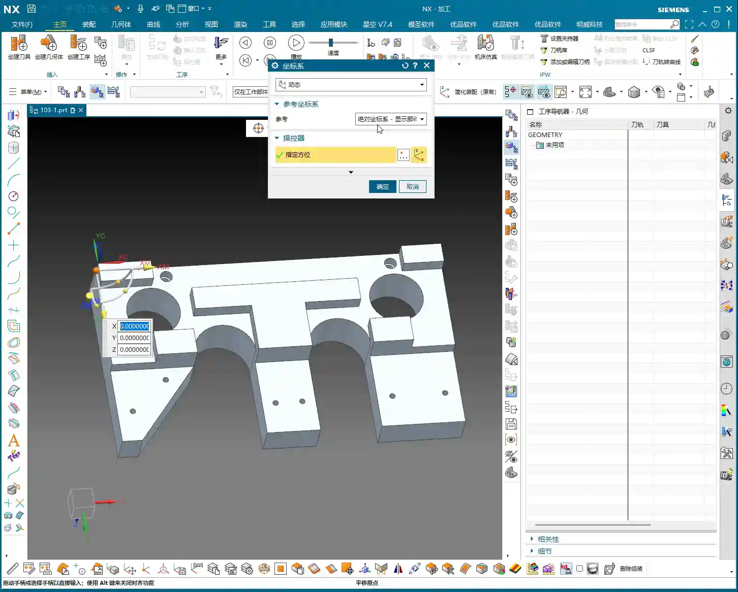
First off, let’s clear out any previously assembled geometries. Consider it a clean slate, so nothing unnecessary gets in our way.
- Coordinate System Setup: The Machine Coordinate System (MCS) can be placed anywhere for now; you can always adjust it in NX. But remember, in actual machining, datum points like G54, G55 must be set precisely. Even a tiny error means a scrapped part!
- Specify Part: Select the solid body we intend to machine – in this case, the “B-surface” shaped part. This is what the toolpath will follow.
- Specify Blank: Just use a simple block blank, or specify it based on actual conditions. I usually prefer to make it slightly oversized to leave some machining allowance.

Selecting the “Solid Profile 3D” Operation
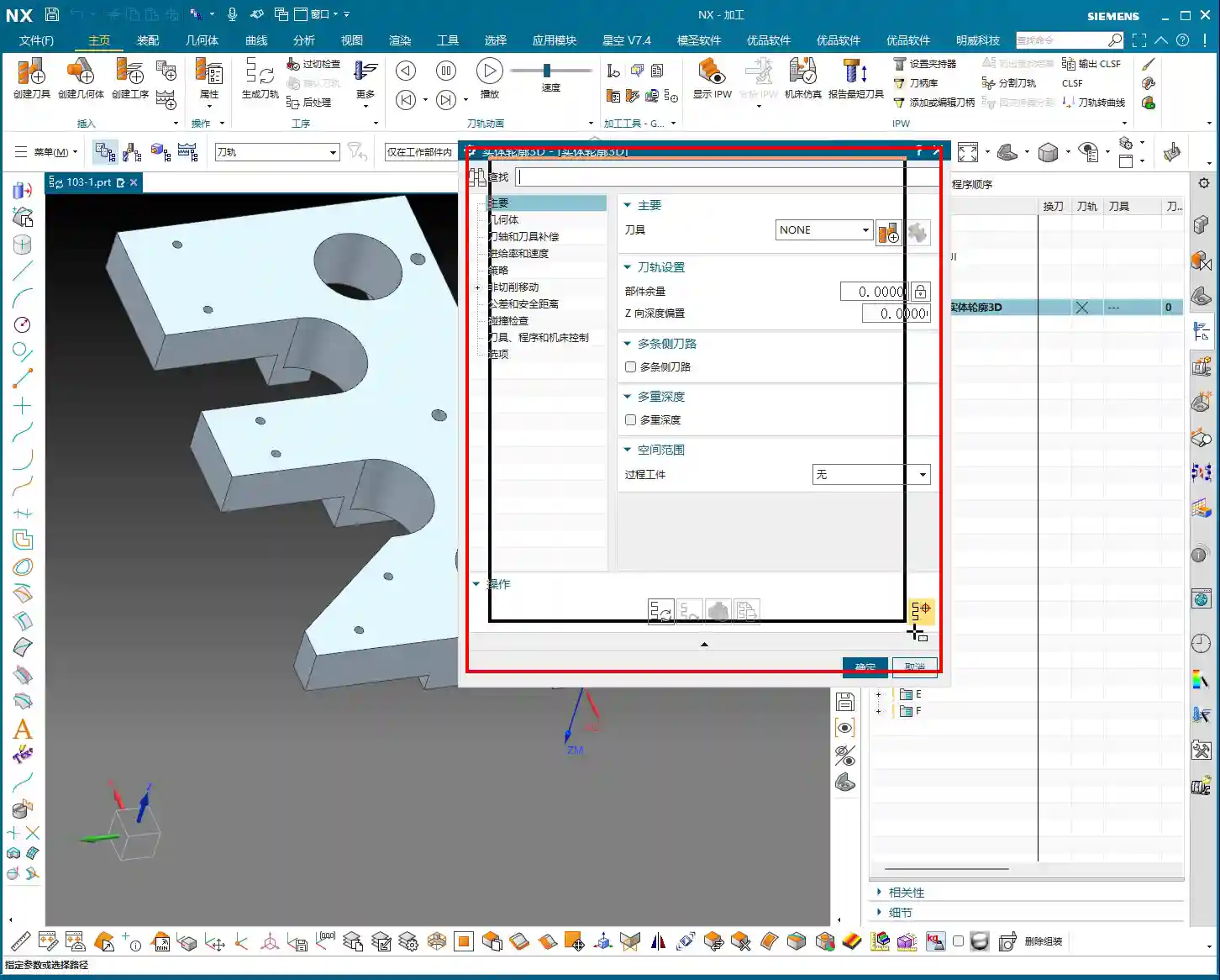
In the “Insert” menu, find “Operation,” select “Mill Multi-Axis” as the machining type, and then locate our main event for today – “Solid Profile 3D.” The name itself tells you what it does: it primarily follows the solid’s profile, and it’s three-dimensional.

Parameter Settings: Depth, Edge Following – Details Make or Break It
Once you’re in the operation dialog, you’ll notice it’s a bit different from the usual planar or cavity milling operations. However, the core logic remains the same: tool, geometry, and method.

Tool and Geometry
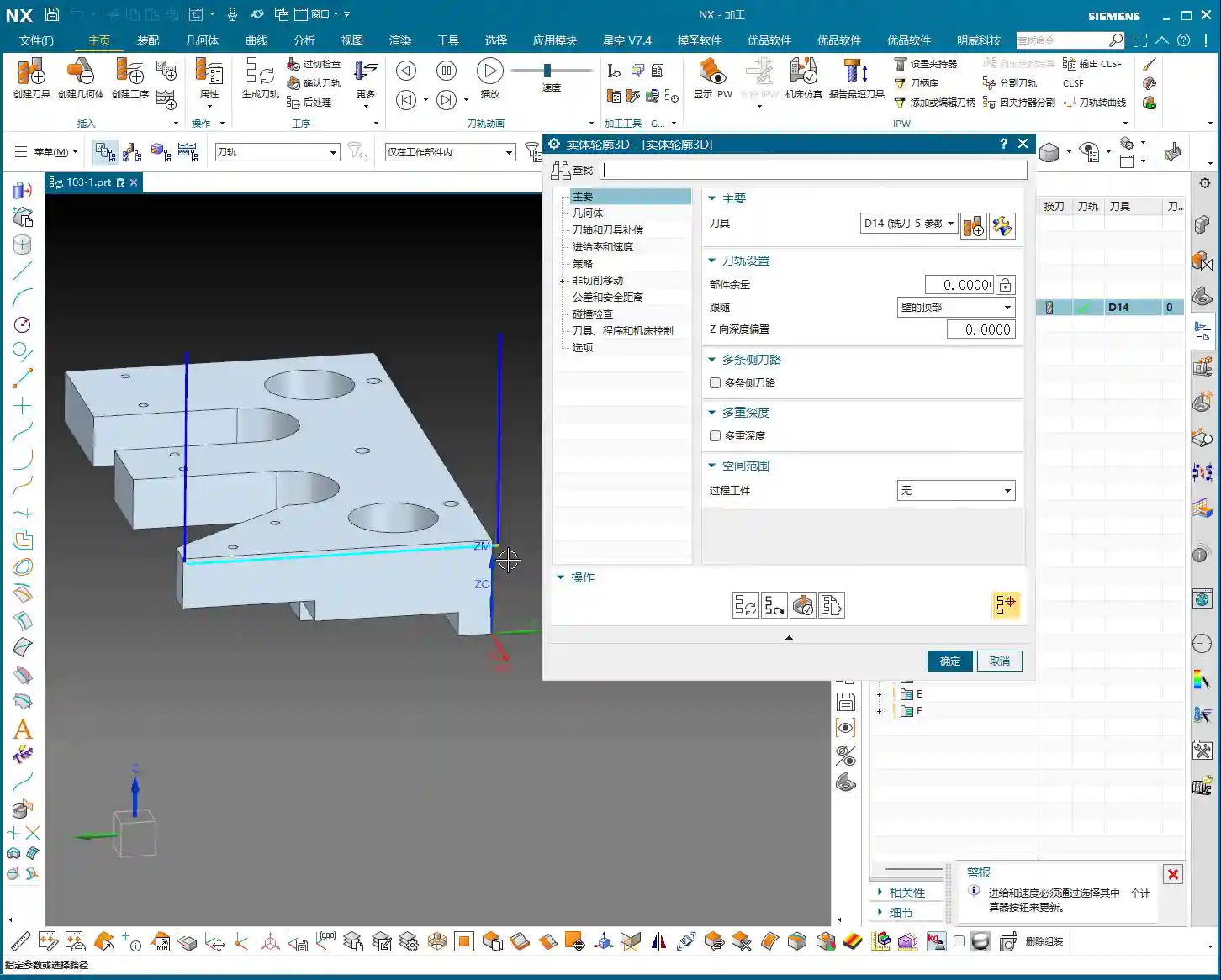
- Tool Selection: Typically, you’ll choose a ball end mill or a corner radius end mill. Since the tool needs to follow the bottom profile, a ball end mill offers the best adaptability. Let’s use a D10 (10mm diameter) ball end mill as an example. The actual tool dimensions, material, and coating must be selected based on your workpiece material and precision requirements – this is serious business.
- Part Stock: This is standard practice: leave 0.1mm stock for a finishing pass or subsequent polishing.
- Bottom Follow: Listen closely, this is one of the key features of “Solid Profile 3D.” We need to select the “B-surface,” which is the bottom face of the part. The tool will tightly follow this bottom contour. If you select the top, it will only machine the top surface.
Core Parameters: Z-Axis Depth Offset and Stepover
These two parameters are what we need to really master today. They dictate how the tool “digs” downwards and “skims” sideways.
- Z-Axis Depth Offset (Z-offset): This parameter controls how much the tool offsets downwards along the Z-axis relative to the bottom B-surface.
- If you input a positive value, for example 10mm, the tool will try to offset 10mm downwards from the B-surface. However, if your part depth isn’t enough for 10mm, or the offset is too large, the toolpath might not generate, or you could even end up with “air cuts.”
- Practical Application: We usually input a small negative value, or simply 0, to make the tool start cutting from the B-surface. If you want to cut slightly deeper, for example, when machining a deep slot with a fillet where the bottom needs to be thoroughly cleaned, you can set it to -0.5mm or even -1mm. This makes the tool cut slightly below the B-surface to completely clear any residual material at the bottom. But don’t overdo it, or you risk tool collision or even tool breakage.
- Multiple Depths: This is what we commonly refer to as “Depth of Cut (DOC)” or “Stepdown.” For example, cutting 1mm per layer. This is the vertical cutting amount.
- Multi-Layer Side Passes / Stepover (Side Steps): This is crucial; it controls the tool’s cutting width in the horizontal direction.
- Simply put, this is the “lateral version” of “Multiple Depths.” If you input a total offset of 10mm and set an incremental step of 1mm per layer, the tool will perform multi-layer cutting outwards (or inwards, depending on direction) from the selected profile, offsetting 1mm per layer for a total offset of 10mm.
- Practical Application: We can use this for a finishing pass on sidewalls, or for progressively removing stock from sidewalls. For example, using a small-diameter tool and taking several passes along the sidewall contour can improve surface finish and achieve higher precision. Remember, the Stepover must not be too large, otherwise it can lead to heavy tool engagement, causing chatter, and ruining the surface texture.
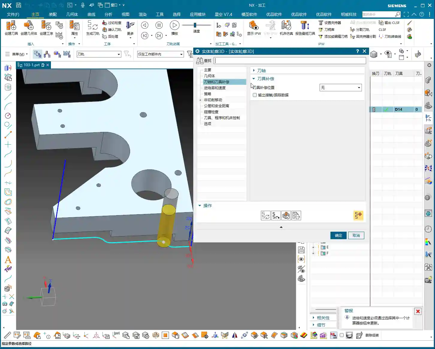
Tool Axis and Cutting Parameters
For tool axis direction, usually, you’d select “None,” meaning the tool plunges perpendicular to the XY plane. If you have a 5-axis machine or the part has specific angled surfaces, you’ll need to adjust the tool axis accordingly. Cutting parameters, including spindle speed and feed rate, must be determined by comprehensively considering the tool, material, and machine rigidity. Don’t just rely on software simulations; the sparks and sounds during actual cutting provide the most authentic feedback!
- Spindle Speed (RPM): S2000 (Example, adjust specifically based on material and tool)
- Feed Rate: F800 (Example, adjust specifically based on material and tool)
Toolpath Generation and Optimization: Seeing is Believing
Once all parameters are set, click to generate the toolpath. You’ll see the tool follow your specified B-surface contour, progressing layer by layer according to the defined depth and Stepover.
Optimization Options: Don’t underestimate these optimizations. They can help reduce air cuts, make toolpaths smoother, and ultimately boost machining efficiency. For example, in “Cutting Moves,” using smooth arc entry and exit motions is better than straight plunges, as it reduces impact.
Summary: Pitfall Avoidance Guide
- Z-Axis Depth Offset: This value requires extreme caution. Too large, and it can lead to air cuts or failure to generate a toolpath; too small, and it might not fully clear the bottom surface. Adjust flexibly based on actual needs; try a small negative value for a thorough bottom cleanup.
- Stepover: Don’t get greedy for speed. Too large a Stepover can lead to uneven tool loading, causing chatter marks and compromising surface quality. Especially during a finishing pass, it’s better to take a few extra passes to ensure stability and precision.
- Applicability of “Solid Profile 3D”: Primarily used for machining along the bottom contour of a part, especially suitable for parts with complex contoured bottoms. For simple planar surfaces or steps, standard cavity milling or planar milling will be more efficient.
- Machine Precision: Even the best programming needs matching machine precision. A ±0.005mm accuracy requirement doesn’t just test your Siemens NX programming; it also tests machine maintenance and compensation. Regularly check machine precision, especially lead screw backlash – that’s invaluable real-world experience!
- Tool Selection: Ball end mills or corner radius end mills are preferred, but the tool’s stick-out length, flute length, and diameter must all match the machining depth and cavity size. Long-reach tools will chatter significantly and are prone to chipping; don’t expect a high surface finish from them.
- Collision Checking: While collision checking in Siemens NX is convenient, don’t rely on it completely. You must thoroughly review toolpath simulations, and even manually drag the tool, pausing to observe at critical points – that’s the safest approach.
- Corner Handling: In “None” mode, the toolpath will have sharp corners; if you select “Overlap” mode, NX will generate a rounded transition for the toolpath. This is highly beneficial for smoother cutting and tool protection.
Alright, that wraps up our discussion on “Solid Profile 3D.” Remember, software is just a tool. What truly makes a successful job is your process thinking and hands-on experience. Observe more, learn more, and get your hands dirty – only then can you evolve from a “programmer” into a true “master machinist”! We’ll cover something different next time.
👤 About the Author:
The author is a veteran CNC machining professional with 15 years of industry experience, specializing in UG NX programming. This article is an original work representing personal practical insights.
⚠️ Copyright Notice: Unauthorized reproduction or distribution without prior communication is strictly prohibited.
Leave a Reply