Tag: CNC Programming

  • Master Wang’s Practical Guide: Optimizing First Operation Roughing Programming for Multi-Operation P

    📝 Key Takeaways:

    Optimizing Multi-Operation Roughing in NX

    M…

    [VIDEO_HERE]

    Master’s Insight: Part Overview and Machining Strategy

    Hello everyone, I’m Master Wang. Today, let’s talk about a typical multi-operation part, specifically the first operation’s roughing. There’s a lot to it – things you won’t learn from textbooks. Many young programmers using NX often end up with disorganized toolpaths, excessive air cuts, and low machining efficiency. That’s simply unacceptable! Today, I’ll teach you how to optimize these roughing toolpaths in NX to be precise and efficient, saving both tool wear and time.

    Initial Part Analysis and Machining Sequence

    Listen up, for this part, we need to perform three-sided machining. First, we’ll machine one side, then its back face, and finally address the front face. Of course, you could also machine the back face first, then the front face; either approach is fine. The key is to clearly understand the machining sequence and the characteristics of each face.

    The top and bottom surfaces of this part are parallel, and most of its side faces are straight. Its Z-axis width is approximately 130 to 140 mm (approx. 5.1 to 5.5 inches), and the raw material thickness is 36 mm (approx. 1.4 inches). Keep these basic dimensions in mind. We’ll first define a machining datum. Typically, we select the back face and Face Mill it flat to serve as the primary datum surface.

    Machining Datum and Stock Definition

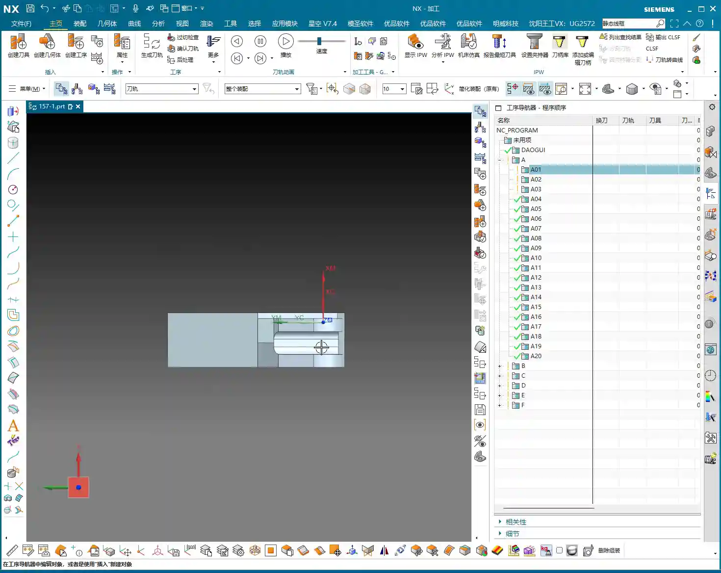
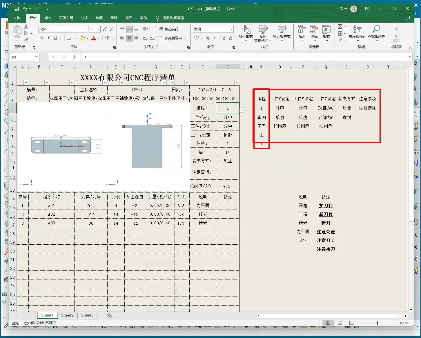
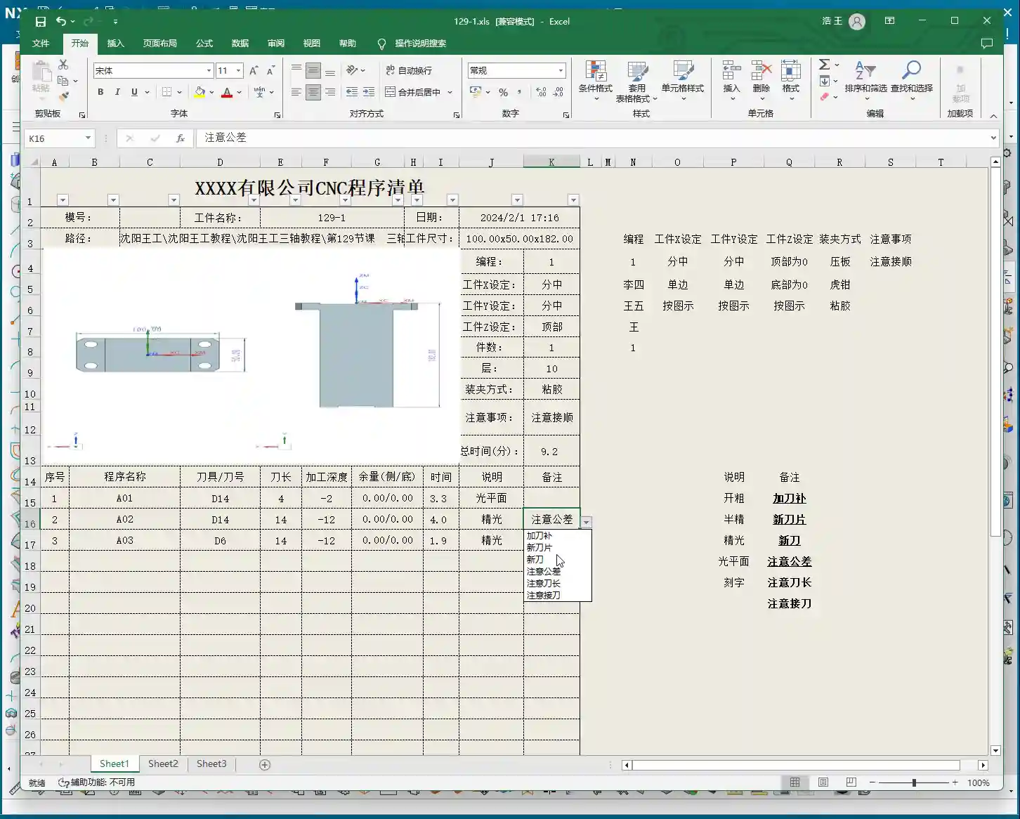
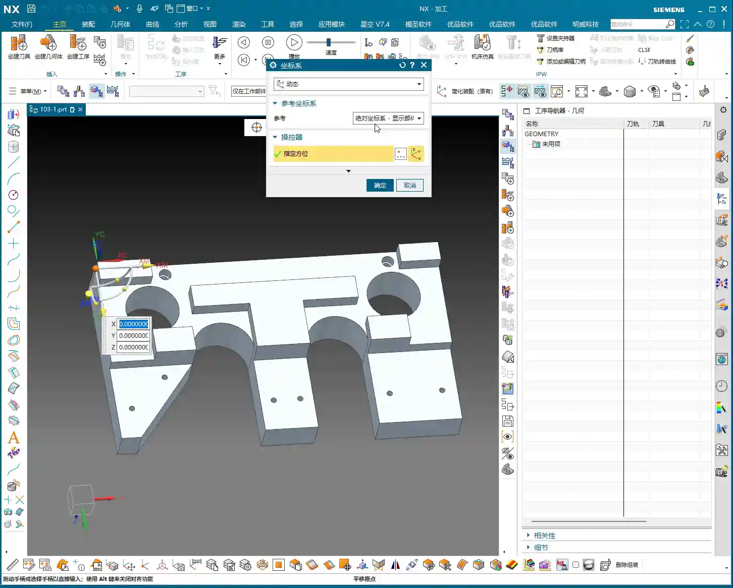
    When programming in NX, the first step is to establish the Work Coordinate System (WCS). For this part, clamped in a vise, let the Z-axis point downwards, and ensure the part is properly oriented. Stable positioning and secure clamping are absolutely fundamental. Without them, even the best program is useless.

    In NX, remember to organize the part, stock, and external contours into separate layers for easy management.
    * Place the Part on Layer 10
    * Place the Stock on Layer 100
    * Place the External Contour on Layer 200
    This way, your operations will be clean, clear, and easy to follow.

    Tool Selection: Experience and Dimension Matching

    Selecting a tool isn’t just grabbing any random one; you need to consider part features, efficiency, and tool life. This is a hands-on skill based on real experience, something you can’t fully learn just from a tool catalog.

    Main Roughing Tool: D10 Flat End Mill

    After reviewing the part, most areas have generous radii, and some sections are quite wide. Therefore, a D10 flat end mill is the most suitable choice as our primary roughing tool.
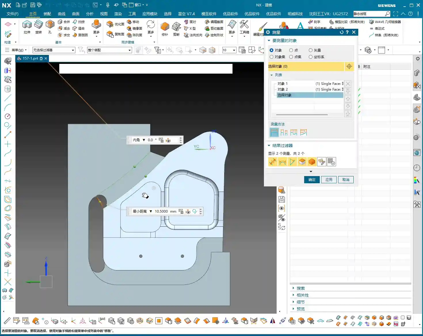
    * The internal corners have R7 and R5 radii, which the D10 end mill can easily navigate without excessive cutting forces.
    * For some narrow areas with an edge clearance of 10.5 mm (approx. 0.41 inches), the D10 can still access and perform roughing.
    * It’s versatile for contouring and slotting, providing high efficiency.

    Finishing and Semi-Finishing Tool: D12R3 Ball Nose End Mill / Torus End Mill

    Don’t forget, the part also has areas with R3 radii, as well as some sections with a width of 15 mm (approx. 0.59 inches). Use a D12R3 ball nose end mill (or a torus end mill) to handle these areas, serving both for semi-finishing after roughing and preparing for the finish cut. This D12R3 tool offers good rigidity and can also handle some R5 areas, killing two birds with one stone.

    Small Contours and Corner Cleanup: D6 Flat End Mill / Ball Nose End Mill

    When encountering small contours, deep cavities, or corners that the D10 or D12R3 can’t reach, you’ll need to use a D6 flat end mill or a D6 ball nose end mill. This is an excellent tool for corner cleanup, but it’s primarily used for finishing or as an aid in secondary roughing. Try to avoid using it for heavy-duty roughing.

    NX Programming in Practice: Roughing Strategies and Toolpath Optimization

    Alright, with the tools selected, now let’s see how to master them in NX. Remember, don’t just rely on software simulations; pay attention to the cutting sparks! That’s the real machining state.

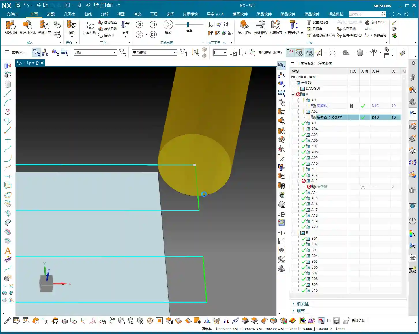
    Initial Face Milling (Back Face)

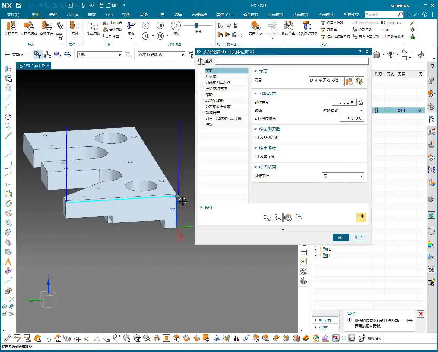
    First up is Face Milling the back face; this is straightforward. Use the D10 flat end mill for a Face Milling operation, directly machining down to the final stock thickness. Since this face typically doesn’t have strict tolerance requirements, the main goal is to create a flat datum surface. In a word: speed!

    Part Draft Angle Analysis and Machining

    Our part isn’t entirely flat; it definitely has draft angles. In NX, use Draft Analysis to see: green areas are flat, while yellow and red areas indicate draft or sloped surfaces. For these sloped surfaces, especially small contours, improper toolpath selection during roughing can lead to incomplete machining or overcutting. You need to clearly understand which faces are flat and which are sloped to select the appropriate cutting method.

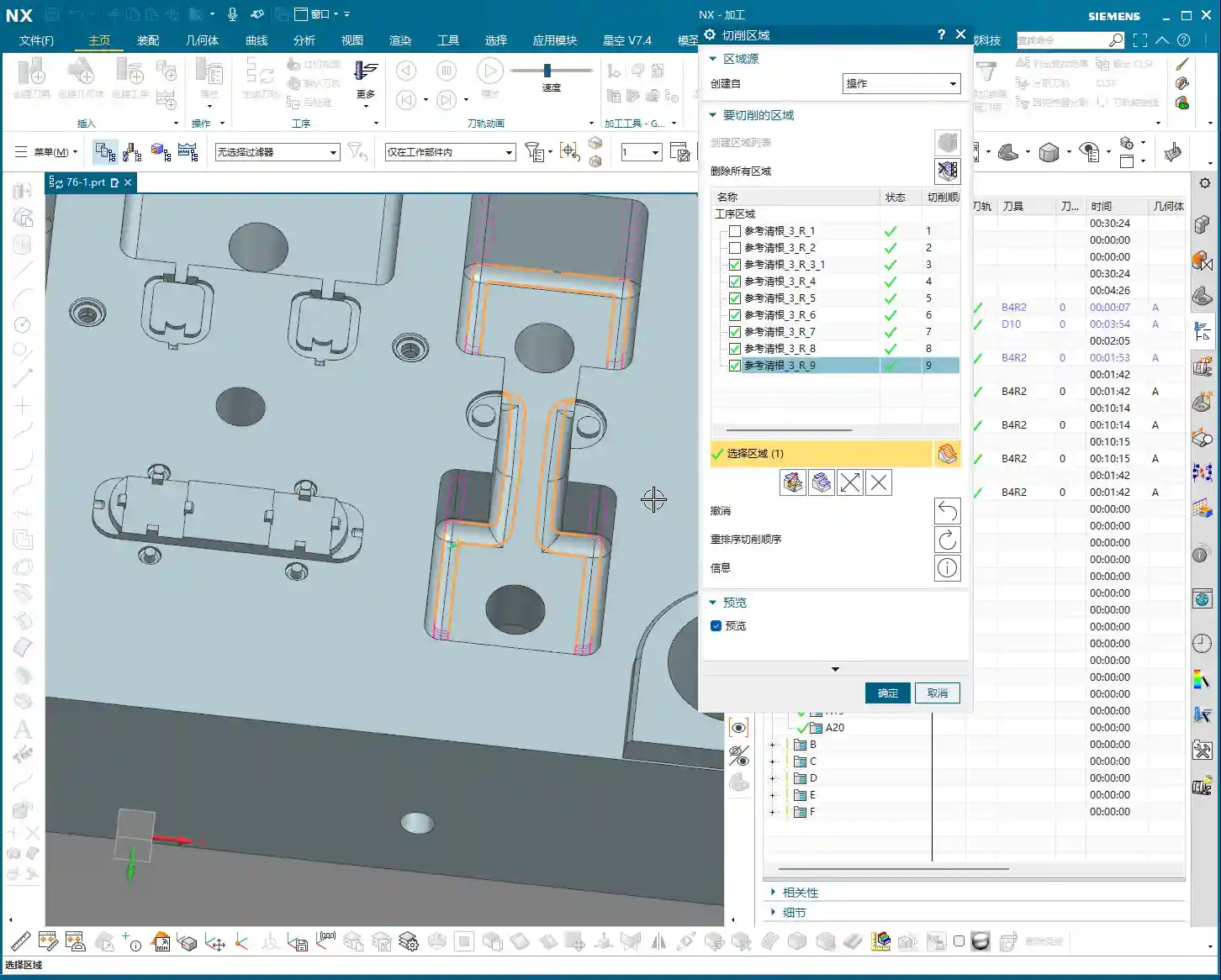
    Avoiding Air Cuts and Inefficient Machining: The Clever Use of Auxiliary Surfaces

    This is the crucial point for today’s discussion! Many young programmers in NX, as soon as they start, have the tool wandering everywhere, resulting in a multitude of air cuts and poor efficiency. Why? Because you haven’t told it which areas *not* to cut!

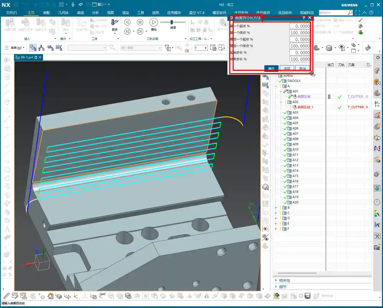
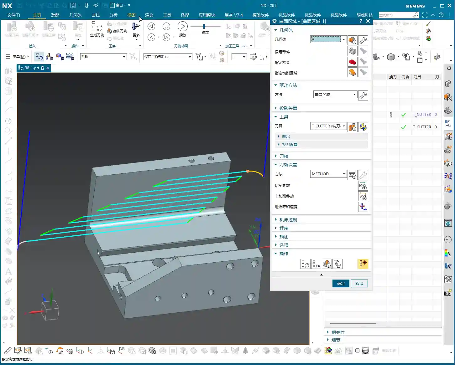
    When we perform roughing, especially contour roughing on the front face, the target area is specific. However, NX’s default roughing algorithms will try to machine all available areas. What to do? Use auxiliary surfaces! This is a tried-and-true trick in practical machining.

    **Master Wang’s Auxiliary Surface Techniques:**
    1. **Limit Machining Area:** For areas you don’t want to machine, such as the exterior of the part or other irrelevant faces, use NX’s ‘Extend Sheet’ command to slightly extend them outwards, or use the ‘Thicken’ command to add a layer, or even directly use ‘Extrude’ or ‘Revolve’ to create a simple blocking surface.
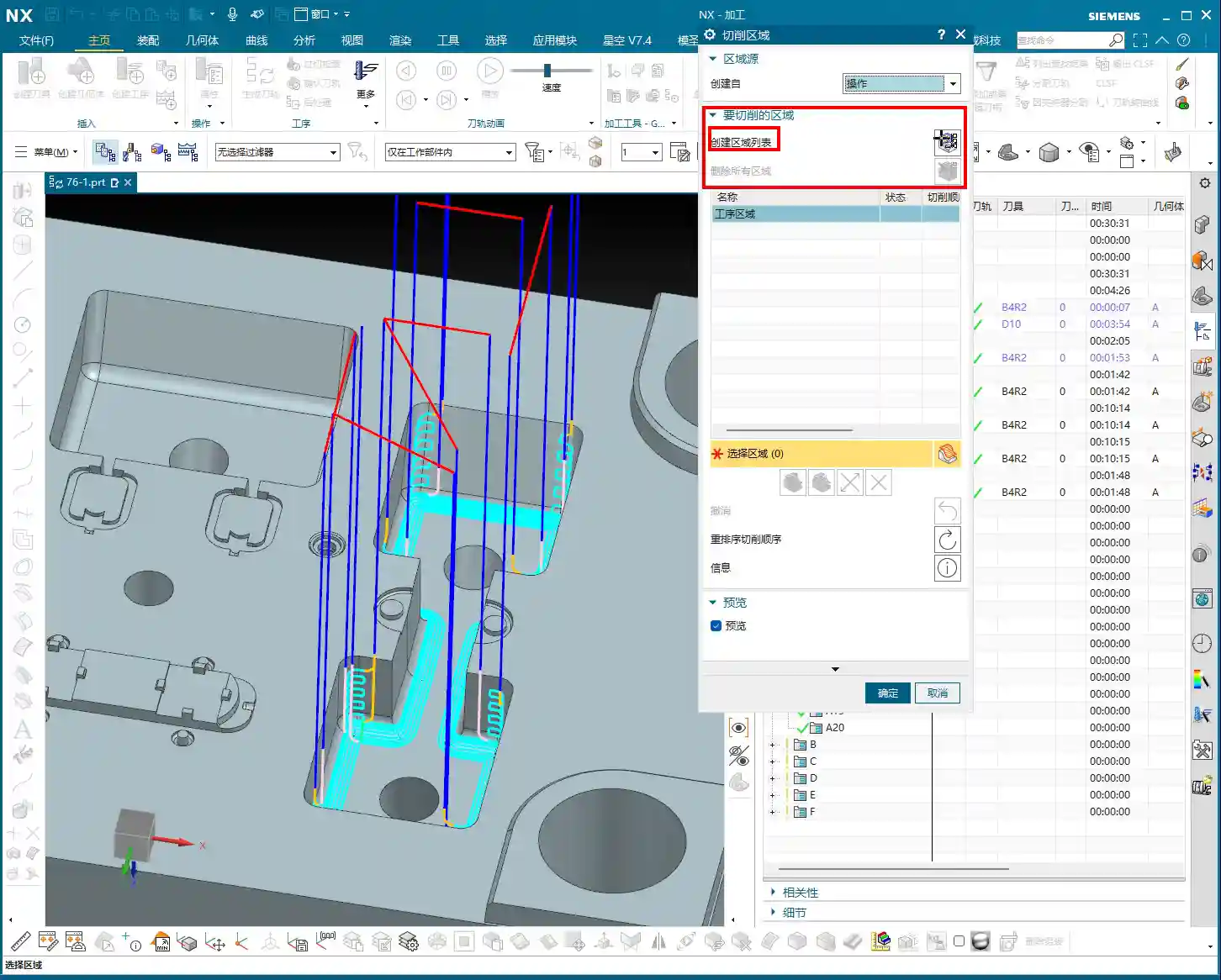
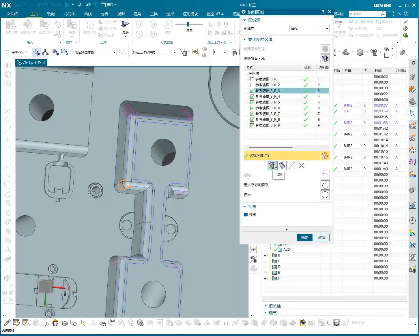
    2. **Define Restricted Zones:** These auxiliary surfaces essentially create “no-go zones” for the tool, letting the toolpath know where it shouldn’t go and where it can machine.
    * For example, if you only want to machine the part’s internal contour, cover the external areas with auxiliary surfaces, ensuring the tool only travels within them.
    * Conversely, if you want to clean up the external contour, use auxiliary surfaces to “block off” the internal areas.
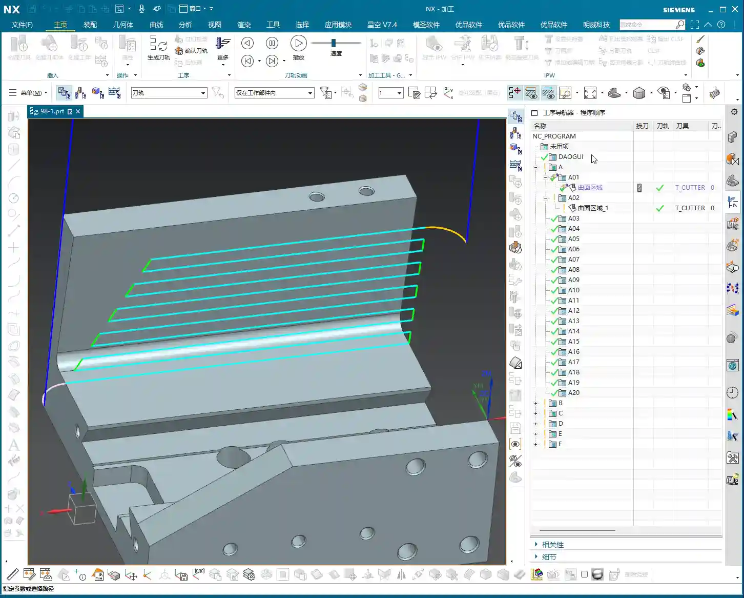
    3. **Reduce Air Cuts:** This way, the tool will obediently work only in the areas you intend to rough, significantly reducing air cutting time and boosting machining efficiency. Don’t foolishly let the tool wander aimlessly across the entire stock.
    4. **Precision Requirements:** Remember, auxiliary surfaces don’t need perfect precision; they just need to effectively block the toolpath, saving time and effort. The purpose is to make the toolpath smarter, not to draw more precise models.

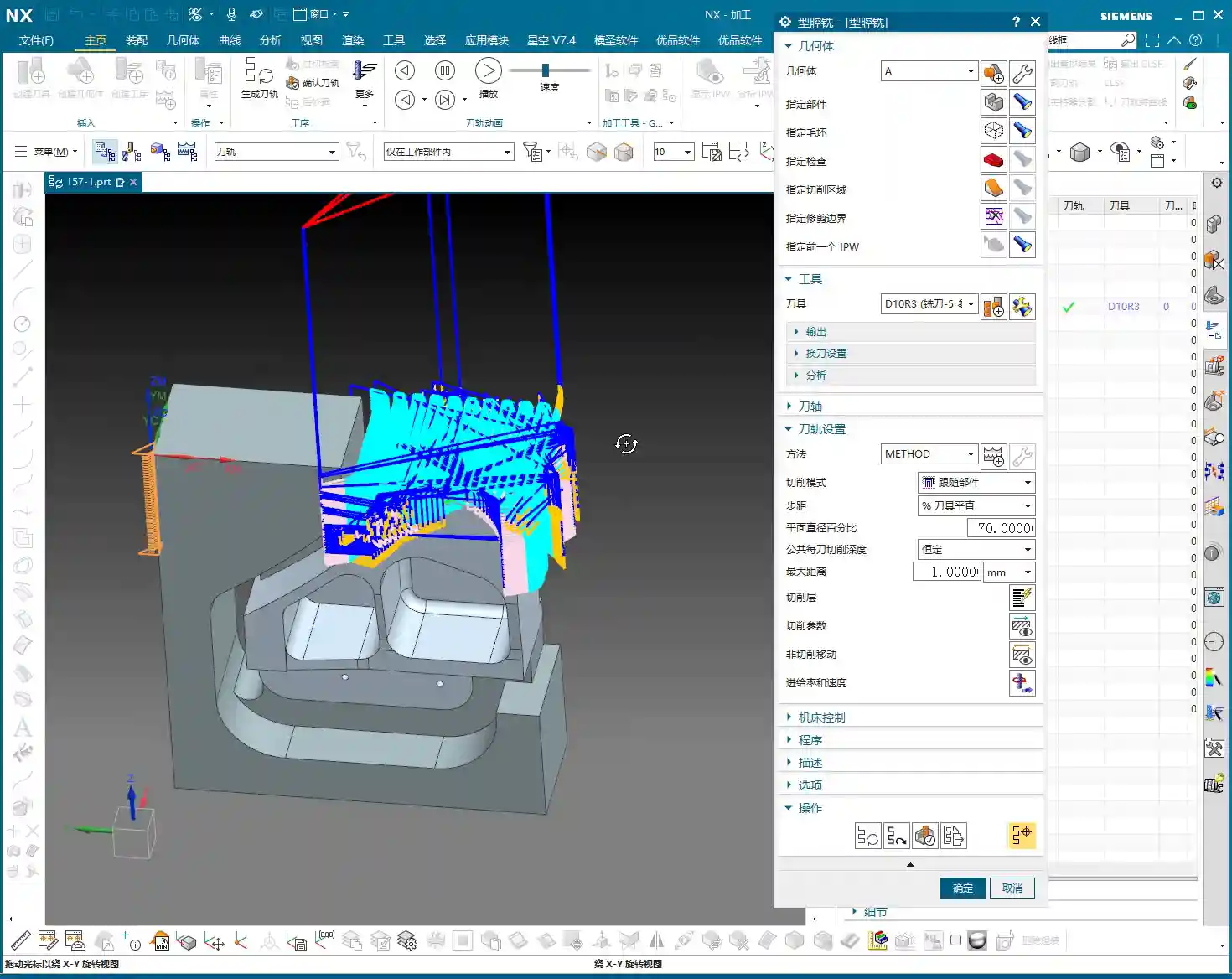
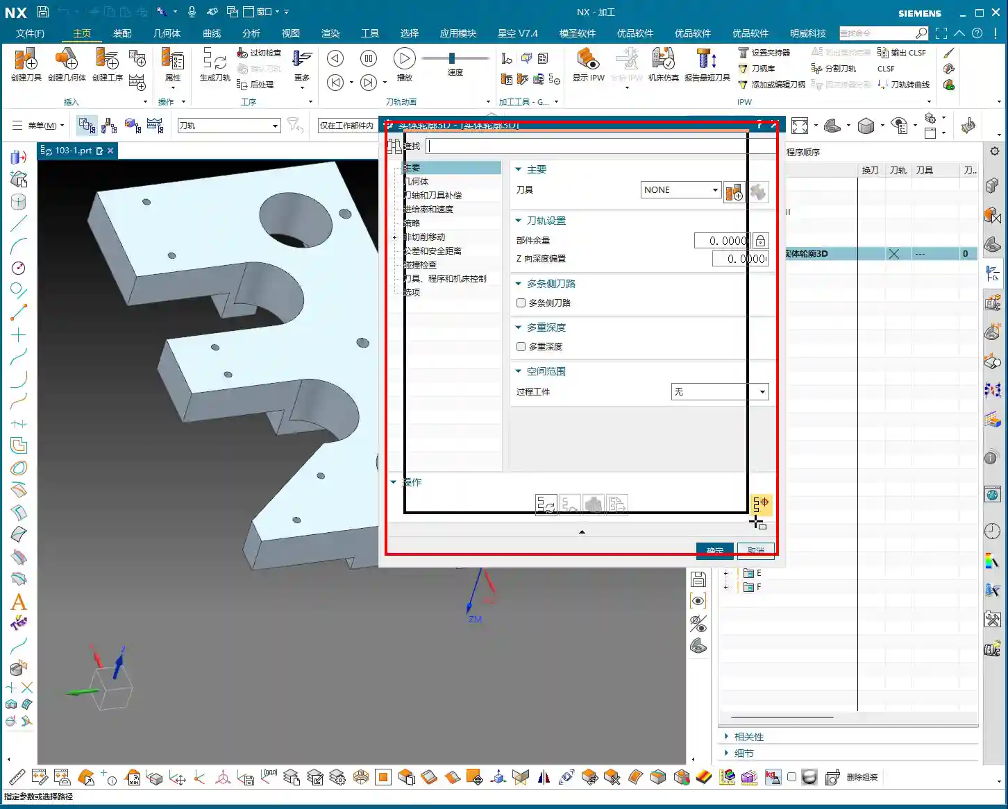
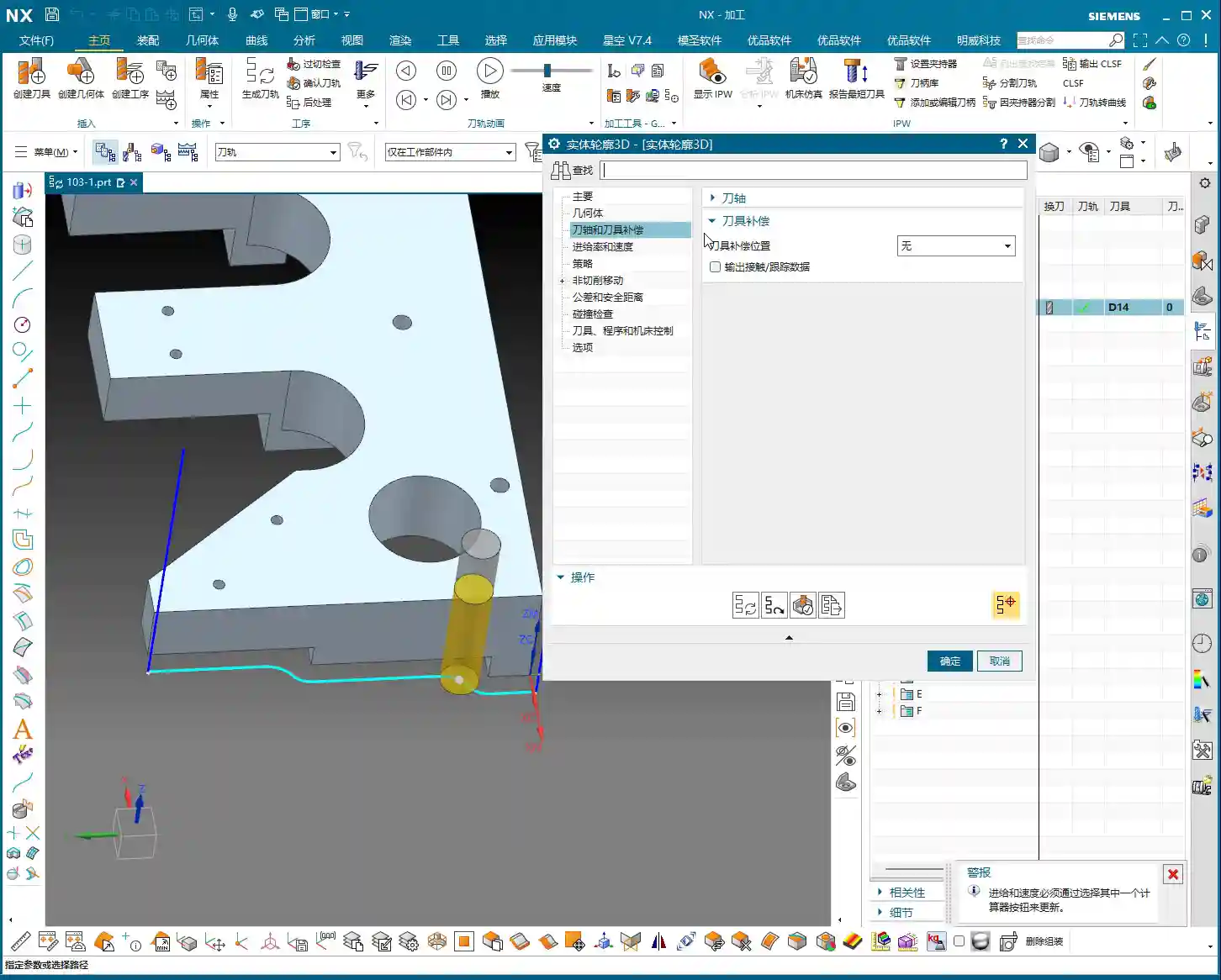
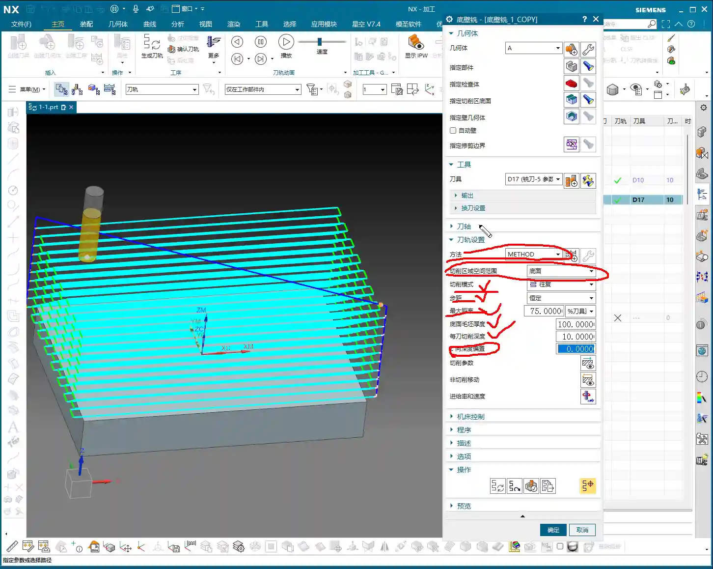
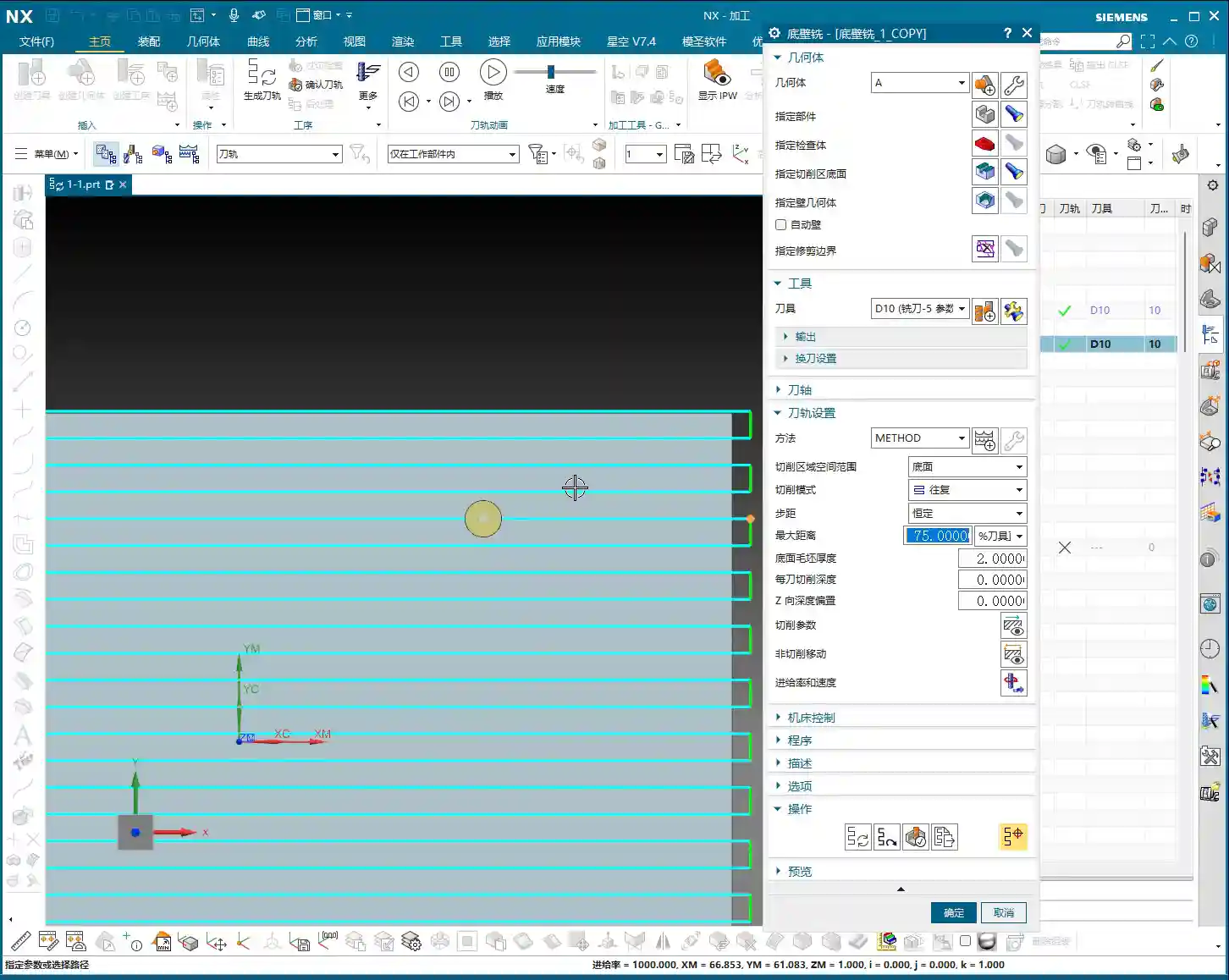
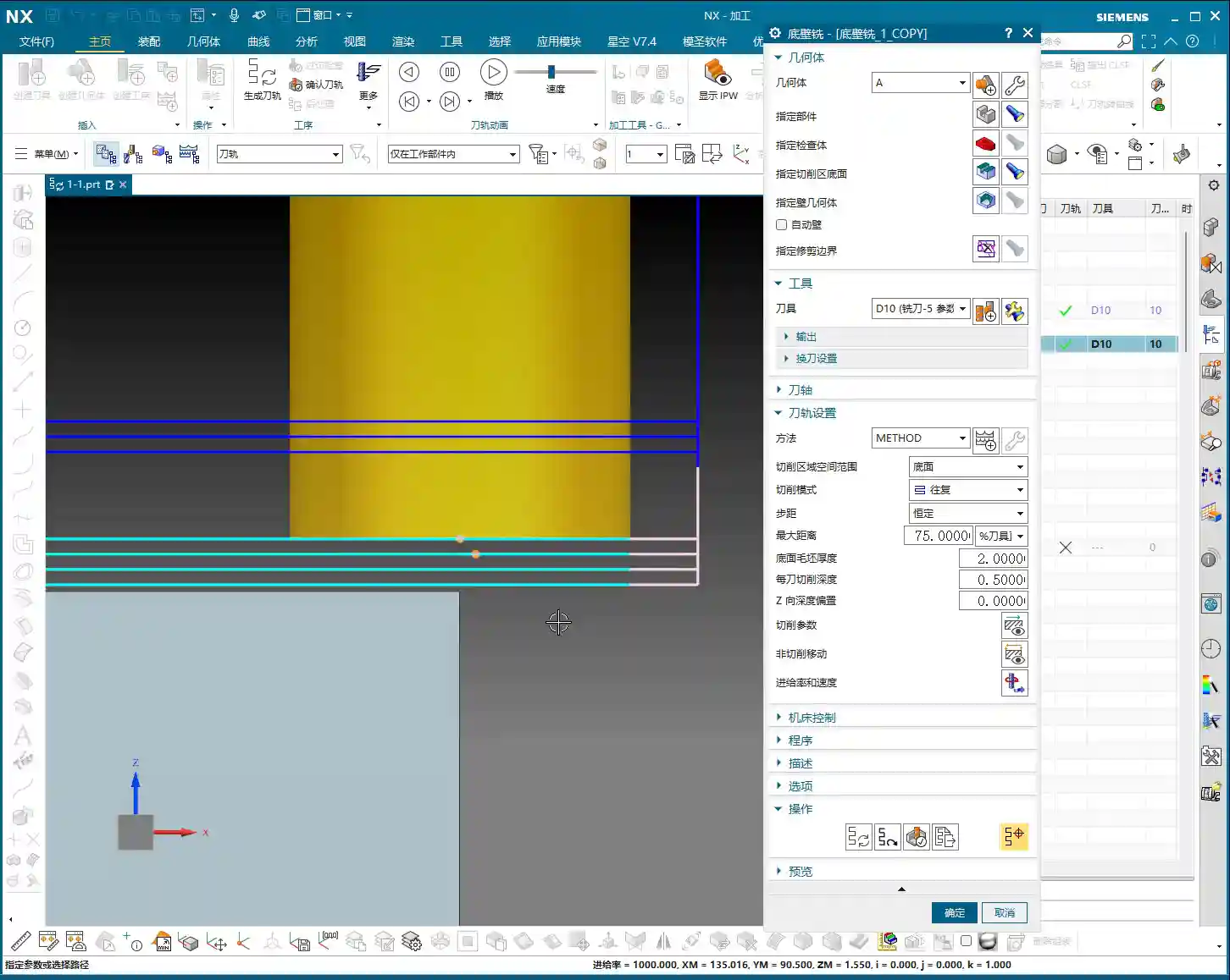
    Contouring and Depth of Cut Control

    For contour areas, we’ll use NX’s ‘Contour Milling’ or ‘Cavity Milling’ operations. The Depth of Cut must be determined based on material hardness and tool strength. For aluminum, you can go deeper. For titanium alloys and high-temperature nickel-based alloys, you need to be more conservative, with depths of 0.5 mm (approx. 0.02 inches) or even 0.2 mm (approx. 0.008 inches) possibly being necessary. Don’t just rely on software parameters; observe the cutting sparks and chip condition – those are the most authentic feedback.

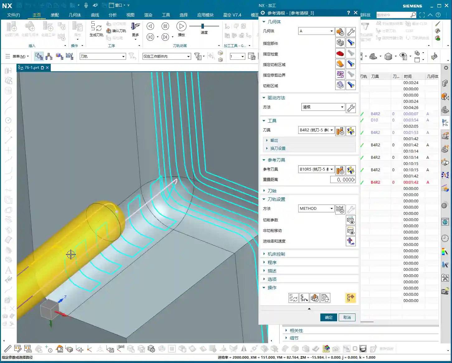
    Be sure to utilize NX’s ‘Reference Tool’ function to prevent the tool from re-cutting previously machined areas during secondary roughing, and to effectively avoid overcutting. For instance, if you’ve roughed with a D10, when performing semi-finishing with a D12R3, set the reference tool to D10. The D12R3 will then only machine areas that the D10 couldn’t reach.

    Summary: Pitfall Avoidance Guide

    * **Pitfall One:** Blind programming without analyzing part geometry, leading to excessive air cuts and low efficiency.
    * **Master Wang’s Tip:** Before programming, use NX’s analysis tools (such as Draft Analysis, distance measurement) to thoroughly understand the part’s “personality” before taking action. Don’t just look at drawings; combine them with the 3D model for intuitive assessment.
    * **Pitfall Two:** Not effectively using auxiliary surfaces, causing the tool to make unnecessary passes in irrelevant areas or engage where it shouldn’t.
    * **Master Wang’s Tip:** Flexibly utilize functions like ‘Extend Sheet,’ ‘Thicken,’ and ‘Extrude Body’ to create auxiliary surfaces that limit the tool’s machining range, achieving precise roughing and ensuring toolpaths are perfectly controlled.
    * **Pitfall Three:** Improper tool selection—using a tool that’s too large or too small, or one that doesn’t match the radii.
    * **Master Wang’s Tip:** Select tools based on the part’s smallest radius and the width of the machining area, ensuring both cutting efficiency and quality are met. When necessary, grinding custom tools yourself is a skill only seasoned machinists possess.
    * **Pitfall Four:** Ignoring material characteristics and using a “one-size-fits-all” approach for cutting parameters.
    * **Master Wang’s Tip:** For different materials, feed rate, spindle speed, and Depth of Cut all require adjustment. Aluminum alloys can be machined aggressively, while high-temperature alloys demand slower, steadier parameters. Don’t just follow the manual; observe the cutting sparks, chip color, and shape – the machine is “talking” to you.
    * **Pitfall Five:** Over-reliance on software simulations without considering actual machine conditions.
    * **Master Wang’s Tip:** Software is merely a reference. Machine accuracy, fixture rigidity, coolant supply, and workpiece clamping deformation are all critical factors affecting machining. For the first part, always perform a low-speed, small-feed trial cut, and only increase speed once confirmed everything is correct. Experience is paramount!

    👤 About the Author:
    The author is a veteran CNC machining professional with 15 years of industry experience, specializing in UG NX programming. This article is an original work representing personal practical insights.

    ⚠️ Copyright Notice: Unauthorized reproduction or distribution without prior communication is strictly prohibited.

  • Siemens NX (UG) Operation Sheet for Setup A: A Practical Deep Dive – Master Wang Teaches You How to

    📝 Key Takeaways:

    Siemens NX (UG) Operation Sheet for Setup A: Practical Deep Dive

    [VIDEO_HERE]

    Overview: The Importance and Core Function of the Operation Sheet

    Listen up, folks! In mechanical machining, no matter how perfectly you program toolpaths in Siemens NX, if you can’t clearly convey that information to the shop floor operators, it’s all for nothing. The operation sheet, simply put, is the ‘interpreter’ and ‘guidebook’ connecting us programmers with the machine operators. It absolutely must clearly detail how to fixture the part, which face is up, what areas to machine in each step, what tools to use, and what precautions to take. Today, we’re going to start with the most fundamental and critical Setup A operation sheet, and I’ll walk you through how to generate it, and more importantly, how to interpret and effectively utilize it!

    Siemens NX (UG) Operation Sheet Generation: Practical Steps

    Step One: Select Programs for Output and Initial Verification

    In Siemens NX, first, select all the toolpath programs you want to output an operation sheet for (e.g., A01, A02, A03 for Setup A). Once selected, here’s a good habit: always simulate the toolpaths first to ensure there are no issues and that the fixturing is appropriate.

    For a part like this one, Setup A involves machining a single face. So, when clamping, you need to secure the part in a vise, exposing the face to be machined. Simulating it gives you a clear understanding. It also provides the operator with a visual machining preview, building confidence and reducing the chance of errors.

    Step Two: Select the ‘Generic Operation Sheet’ Function

    Toolpaths are good, programs are selected. Next, it’s time for the crucial step of outputting the operation sheet. In the Siemens NX menu, find the ‘Generic Operation Sheet’ option. For us, this is usually achieved through the ‘Starry Sky’ plugin. Just click it.

    Step Three: Understand Output Options and Path Settings

    Once open, you’ll see several output types:

    • ‘Post-Process and Output Operation Sheet’: This means outputting both the G-code (post-processed file) and the operation sheet simultaneously.
    • ‘Output Operation Sheet Only’: This outputs only the operation sheet; we can handle the G-code separately later.
    • ‘Output Post-Process Only’: This outputs only the G-code.

    Since we’re focusing on operation sheets today, select ‘Output Operation Sheet Only’. When you do, you’ll notice the ‘Post-Process List’ section is empty. That’s perfectly normal, just ignore it. As for the ‘Tables’ and other options below, those are more detailed settings we’ll cover later; you can safely disregard them for now.

    Regarding the output path, many people just stick with the default. But listen up, I, Master Wang, have a personal habit: I typically create a dedicated ‘NC’ folder on my D: drive or another non-system drive, and I put all post-processed files and operation sheets in there. This makes management easier, finding files quicker, and prevents clutter. You might want to adopt this practice.

    Step Four: Confirm and Generate the Operation Sheet

    Once all previous settings are configured, just click ‘OK’. No need to mess with any other parameters; the operation sheet will be automatically generated and saved to your specified path.

    In-Depth Interpretation of Key Information in the Setup A Operation Sheet

    Part Basic Information and Datum Reference

    • Dimensions: The operation sheet will clearly specify the part’s length, width, and height. For example, our part here is 100mm long, 50mm wide, and 182mm high. These are the final finish cut dimensions, so the operator knows the part’s size at a glance.
    • Locating Datum: This is critically important! The operation sheet will clearly state the tool offsetting method. For example, here it’s ‘Center X & Y, Top Face Zero’. This tells the operator exactly where the tool offsetting origin is for the X, Y, and Z axes – absolutely no room for error.
    • Views: The automatically generated XY and XZ views from Siemens NX provide a clear visual of the part’s machining faces and tool offsetting points. When operators see these diagrams, they’ll have a crystal-clear understanding of the features to be machined and the datum locations. Don’t just rely on software simulations; look for the cutting sparks! Drawings are merely aids; the shop floor is where reality happens.

    Company and Workpiece Information

    • Mold/Job Number: This section can be filled according to your company’s specific requirements. If you want it to display the company name or a particular mold number, you can preset it in the operation sheet template. How do you modify the template? I’ve covered that in detail in my previous video tutorials; go check them out yourself – it’s fundamental!
    • Workpiece Name: For example, Programmer and Date

      • Prepared By: Here, I’ve put ‘Wang’. You can enter your own name or employee ID. This is also something you modify in the template; set it once, and it will auto-populate thereafter.
      • Date: The specific date and time the operation sheet was generated, such as

    File Path and Dimension Verification

    • Path: The file path where the operation sheet is stored. While it might be long, the operator only needs to know which lesson’s folder (e.g., ‘Lesson 129’) it’s in to find the corresponding NC file. This helps our shop floor colleagues locate the correct file and prevents loading the wrong program.
    • Actual Dimensions: Emphasizing again: 100mm long, 50mm wide, and 182mm high. These are the final finish cut dimensions of the part.

    Clamping Method and Precautions

    • Clamping Method: For example, we’re using a ‘strap clamps’, ‘three-jaw chuck’, Precautions: For instance, Total Machining Time and Sequence Details

      • Total Time: The combined total machining time for all Setup A programs (A01, A02, A03), for example, Sequence Details: The operation sheet will list each specific program segment:

        • Program Name: For example, Tool: For instance, Tool Length: Pay close attention here! This refers to the ‘clamped four units’ (e.g., 40mm). It is NOT the overall tool length! This is a common area for Machining Depth: For example, single depth of cut or the depth of a specific feature, not the final machining depth of the entire part. Understand this in conjunction with the actual toolpath.
        • Description: Such as Remarks: This is a treasure trove! Here, you can jot down all sorts of ‘Pay attention to tolerance’, ‘Change to a new tool’, ‘Mind tool blending’, and so on. These are crucial reminders for the operator to ensure machining quality and efficiency. This section can also be customized in the template; add all your frequently used precautions.

      Master Wang’s Wisdom: Practical Tricks for Operation Sheets

      Just knowing how to generate an operation sheet isn’t enough; the key is knowing how to use it, how to make it ‘come alive’.

      • Division of Labor: Post-Processing vs. Operation Sheet: We choose ‘Output Operation Sheet Only’ because post-processing (G-code) requires separate review and verification, while the operation sheet serves as direct instructions for the operator. Keeping them separate clarifies responsibilities and improves efficiency.
      • The True Meaning of ‘Tool Length’: Remember, the tool length on the operation sheet refers to the fixturing. It’s better to clamp it a bit shorter for more stability than to risk clamping it too long.
      • Applying ‘Machining Depth’ Flexibly: Don’t mistake the ‘machining depth’ in each program segment as the final depth. It could be the single The Value of the ‘Remarks’ Section: This is where your experience truly shines! Here, you can jot down any ‘frequent air blasts’; if a feature has tight tolerances and requires ‘this tool needs to be replaced halfway through machining’. These are all critical for improving machining quality and reducing scrap.
      • Path Standardization: My habit of using a dedicated NC folder on the D: drive is all about Template Customization: This is also a big deal! Integrate your company’s commonly used information, standard operation sheet template. This will save a lot of effort every time you generate one and ensure the Master Wang’s Perspective: The ‘Siemens NX + SEO’ One-Two Punch for Industrial Product Promotion

        Folks, don’t think I, Master Wang, only know how to write code and sharpen tools. In this day and age, even great products need a good shout-out. Our work on operation sheets isn’t just for production; it’s also excellent material for industrial product promotion.

        See, all these detailed processes – Siemens NX modeling, 5-axis simultaneous programming, toolpath optimization, and then today’s topic, operation sheet creation – each step embodies our core technology. Share these practical experiences and technical details through articles, tutorials, and case studies on our official website, industry blogs, or even platforms like Zhihu and Bilibili, accompanied by high-definition Siemens NX screenshots and machining videos. The impact will be completely different!

        For example, you could break down the Setup A machining process for a complex part, from modeling to the operation sheet, explaining it step-by-step. Tag it with ‘Siemens NX 5-Axis Programming’, ‘Complex Surface Milling’, ‘Titanium Alloy Machining Process’, ‘Precision Fixture Design’. When potential customers search for these technical solutions online, they’ll find us. Doesn’t that mean we’re directly showcasing our ‘content marketing’, combined with

    Summary: Pitfall Avoidance Guide

    • Operation Sheet ≠ Post-Processed G-code: They have different functions and different purposes; do not confuse them.
    • Don’t Blindly Trust Times: The machining time on the operation sheet is for reference only; actual conditions may vary due to machine status, operator habits, and other factors.
    • Utilize the Remarks Section: Don’t underestimate the remarks! It’s the most direct and effective Template Standardization: Customize your operation sheet templates in advance. This will not only improve work efficiency but also ensure information accuracy and consistency, reducing human error.
    • 👤 About the Author:
      The author is a veteran CNC machining professional with 15 years of industry experience, specializing in UG NX programming. This article is an original work representing personal practical insights.

      ⚠️ Copyright Notice: Unauthorized reproduction or distribution without prior communication is strictly prohibited.

  • Siemens NX Solid Profile 3D: Master Wang’s Hands-on Guide to Finishing Complex Bottom Profiles, Avoi

    📝 Key Takeaways: Master Wang provides a hands-on explanation of the Siemens NX Solid Profile 3D operation, focusing on finishing complex bottom profiles. Learn practical applications of core parameters like Z-axis depth offset and Stepover, avoiding common pitfalls and boosting efficiency. Discover hard-hitting tips not found in textbooks to elevate your Siemens NX programming skills!

    Master Wang Explains: The Ins and Outs of Solid Profile 3D

    Alright everyone, Master Wang here. Today we’re diving into a Siemens NX feature you might not use often: the “Solid Profile 3D” operation. To be honest, in all my years, I’ve only really needed it a couple of times, which is why I held off talking about it. But listen up: “Rarely used doesn’t mean useless; it can be a lifesaver when it counts!” It truly shines when dealing with specific geometries, especially complex bottom profiles. It has its unique advantages.

    Don’t let its simple operation fool you. Understanding the logic behind it will give you a powerful tool for tackling those “oddball” parts. We’re not wasting time on abstract theories; let’s get straight to the machine and see what it can actually do.

    Preparation: Setting Up Part and Blank, No Room for Error

    When it comes to machining, the first step is always to clearly define your part and blank. Last time I slipped up and modeled the part in the wrong location – that’s a mistake you can’t afford. This time, we’ll start fresh and ensure the foundation is solid.

    Creating the Part and Blank

    First off, let’s clear out any previously assembled geometries. Consider it a clean slate, so nothing unnecessary gets in our way.

    • Coordinate System Setup: The Machine Coordinate System (MCS) can be placed anywhere for now; you can always adjust it in NX. But remember, in actual machining, datum points like G54, G55 must be set precisely. Even a tiny error means a scrapped part!
    • Specify Part: Select the solid body we intend to machine – in this case, the “B-surface” shaped part. This is what the toolpath will follow.
    • Specify Blank: Just use a simple block blank, or specify it based on actual conditions. I usually prefer to make it slightly oversized to leave some machining allowance.

    Selecting the “Solid Profile 3D” Operation

    In the “Insert” menu, find “Operation,” select “Mill Multi-Axis” as the machining type, and then locate our main event for today – “Solid Profile 3D.” The name itself tells you what it does: it primarily follows the solid’s profile, and it’s three-dimensional.

    Parameter Settings: Depth, Edge Following – Details Make or Break It

    Once you’re in the operation dialog, you’ll notice it’s a bit different from the usual planar or cavity milling operations. However, the core logic remains the same: tool, geometry, and method.

    Tool and Geometry

    • Tool Selection: Typically, you’ll choose a ball end mill or a corner radius end mill. Since the tool needs to follow the bottom profile, a ball end mill offers the best adaptability. Let’s use a D10 (10mm diameter) ball end mill as an example. The actual tool dimensions, material, and coating must be selected based on your workpiece material and precision requirements – this is serious business.
    • Part Stock: This is standard practice: leave 0.1mm stock for a finishing pass or subsequent polishing.
    • Bottom Follow: Listen closely, this is one of the key features of “Solid Profile 3D.” We need to select the “B-surface,” which is the bottom face of the part. The tool will tightly follow this bottom contour. If you select the top, it will only machine the top surface.

    Core Parameters: Z-Axis Depth Offset and Stepover

    These two parameters are what we need to really master today. They dictate how the tool “digs” downwards and “skims” sideways.

    • Z-Axis Depth Offset (Z-offset): This parameter controls how much the tool offsets downwards along the Z-axis relative to the bottom B-surface.

      • If you input a positive value, for example 10mm, the tool will try to offset 10mm downwards from the B-surface. However, if your part depth isn’t enough for 10mm, or the offset is too large, the toolpath might not generate, or you could even end up with “air cuts.”
      • Practical Application: We usually input a small negative value, or simply 0, to make the tool start cutting from the B-surface. If you want to cut slightly deeper, for example, when machining a deep slot with a fillet where the bottom needs to be thoroughly cleaned, you can set it to -0.5mm or even -1mm. This makes the tool cut slightly below the B-surface to completely clear any residual material at the bottom. But don’t overdo it, or you risk tool collision or even tool breakage.

    • Multiple Depths: This is what we commonly refer to as “Depth of Cut (DOC)” or “Stepdown.” For example, cutting 1mm per layer. This is the vertical cutting amount.
    • Multi-Layer Side Passes / Stepover (Side Steps): This is crucial; it controls the tool’s cutting width in the horizontal direction.

      • Simply put, this is the “lateral version” of “Multiple Depths.” If you input a total offset of 10mm and set an incremental step of 1mm per layer, the tool will perform multi-layer cutting outwards (or inwards, depending on direction) from the selected profile, offsetting 1mm per layer for a total offset of 10mm.
      • Practical Application: We can use this for a finishing pass on sidewalls, or for progressively removing stock from sidewalls. For example, using a small-diameter tool and taking several passes along the sidewall contour can improve surface finish and achieve higher precision. Remember, the Stepover must not be too large, otherwise it can lead to heavy tool engagement, causing chatter, and ruining the surface texture.

    Tool Axis and Cutting Parameters

    For tool axis direction, usually, you’d select “None,” meaning the tool plunges perpendicular to the XY plane. If you have a 5-axis machine or the part has specific angled surfaces, you’ll need to adjust the tool axis accordingly. Cutting parameters, including spindle speed and feed rate, must be determined by comprehensively considering the tool, material, and machine rigidity. Don’t just rely on software simulations; the sparks and sounds during actual cutting provide the most authentic feedback!

    • Spindle Speed (RPM): S2000 (Example, adjust specifically based on material and tool)
    • Feed Rate: F800 (Example, adjust specifically based on material and tool)

    Toolpath Generation and Optimization: Seeing is Believing

    Once all parameters are set, click to generate the toolpath. You’ll see the tool follow your specified B-surface contour, progressing layer by layer according to the defined depth and Stepover.

    Optimization Options: Don’t underestimate these optimizations. They can help reduce air cuts, make toolpaths smoother, and ultimately boost machining efficiency. For example, in “Cutting Moves,” using smooth arc entry and exit motions is better than straight plunges, as it reduces impact.

    Summary: Pitfall Avoidance Guide

    • Z-Axis Depth Offset: This value requires extreme caution. Too large, and it can lead to air cuts or failure to generate a toolpath; too small, and it might not fully clear the bottom surface. Adjust flexibly based on actual needs; try a small negative value for a thorough bottom cleanup.
    • Stepover: Don’t get greedy for speed. Too large a Stepover can lead to uneven tool loading, causing chatter marks and compromising surface quality. Especially during a finishing pass, it’s better to take a few extra passes to ensure stability and precision.
    • Applicability of “Solid Profile 3D”: Primarily used for machining along the bottom contour of a part, especially suitable for parts with complex contoured bottoms. For simple planar surfaces or steps, standard cavity milling or planar milling will be more efficient.
    • Machine Precision: Even the best programming needs matching machine precision. A ±0.005mm accuracy requirement doesn’t just test your Siemens NX programming; it also tests machine maintenance and compensation. Regularly check machine precision, especially lead screw backlash – that’s invaluable real-world experience!
    • Tool Selection: Ball end mills or corner radius end mills are preferred, but the tool’s stick-out length, flute length, and diameter must all match the machining depth and cavity size. Long-reach tools will chatter significantly and are prone to chipping; don’t expect a high surface finish from them.
    • Collision Checking: While collision checking in Siemens NX is convenient, don’t rely on it completely. You must thoroughly review toolpath simulations, and even manually drag the tool, pausing to observe at critical points – that’s the safest approach.
    • Corner Handling: In “None” mode, the toolpath will have sharp corners; if you select “Overlap” mode, NX will generate a rounded transition for the toolpath. This is highly beneficial for smoother cutting and tool protection.

    Alright, that wraps up our discussion on “Solid Profile 3D.” Remember, software is just a tool. What truly makes a successful job is your process thinking and hands-on experience. Observe more, learn more, and get your hands dirty – only then can you evolve from a “programmer” into a true “master machinist”! We’ll cover something different next time.

    👤 About the Author:
    The author is a veteran CNC machining professional with 15 years of industry experience, specializing in UG NX programming. This article is an original work representing personal practical insights.

    ⚠️ Copyright Notice: Unauthorized reproduction or distribution without prior communication is strictly prohibited.

  • Siemens NX CAM Surface Drive Percentage: Master Wang Teaches You How to Refine Toolpaths, Ditch “Bli

    📝 Key Takeaways: Master Wang personally reveals the practical secrets of Siemens NX CAM’s Surface Drive Percentage! Master the cutting direction and the synergy of six key parameters to precisely control toolpath start and end points, as well as boundary trimming and extension. Effortlessly manage stock allowance for roughing and finishing passes, significantly boosting machining efficiency and part accuracy. Say goodbye to guesswork programming, and take control of both cost and efficiency!

    Hello everyone, I’m Master Wang!

    Today, let’s talk about a particularly practical feature in Siemens NX CAM—Surface Drive Percentage. Textbooks might give you a few concepts, but in our actual work, this feature is crucial for refining toolpaths and boosting both efficiency and accuracy. Listen up, because these are “hardcore” insights I’ve gained from over a decade of hands-on experience at the machine!

    Core Concept: What Exactly is Surface Drive Percentage?

    Simply put, Surface Drive Percentage allows you to precisely control the start point, end point, and extension or trimming along the edges of your toolpath on the drive surface. Don’t underestimate these percentages; when used effectively, your toolpaths will run smoother, machining efficiency will be higher, and part accuracy will be better assured. It’s like drawing a “racetrack” for your tool, telling it where to start, where to stop, and even allowing it to run slightly off the track or finish early.

    Cutting Direction: The “Compass Needle” Determining the Start Point

    Before we dive into percentages, I must emphasize an absolutely critical prerequisite—the cutting direction. The cutting direction you choose directly determines where your “first start point” actually is!
    For instance, if you choose to cut from left to right, then the left side is the start point. If you reverse it to cut from right to left, then the right side immediately becomes the start point. Therefore, every time you adjust the percentages, always confirm that your cutting direction is as expected. Otherwise, you might spend ages adjusting percentages, only to find the results aren’t what you envisioned—because the start point itself has changed!

    Six Key Parameters: The “Scissors” for Toolpath Length and Boundaries

    Unlike “Streamline” operations, which typically only have four parameters, Surface Drive Percentage offers six parameters. These six parameters are divided into two categories: one controls the overall length of the toolpath, and the other controls the toolpath’s extension or trimming along the boundaries.

    1. Toolpath Length Control:

    * First Start Percentage
    * The default value is 0. Setting it to 0 means starting from the beginning of your chosen cutting direction.
    * If set to 20, the toolpath will start cutting 20% inward from the start point, leaving the first 20% untouched.
    * If set to -10 (a negative number), the toolpath will extend outward by 10% from the start point. This is extremely useful in specific situations, such as avoiding clamping elements or allowing the tool to enter the cut in a more stable condition.
    * First End Percentage
    * The default value is 100. Setting it to 100 means machining along the cutting direction all the way to the end of the drive surface.
    * If set to 50, the toolpath will only machine up to 50% of the total length and then stop.
    * If set to 120, the toolpath will extend outward by 20% from the end point. This is particularly effective when you want the tool to completely exit the part before retracting, preventing “witness marks” at the part’s edge.
    * Last Start Percentage
    * This refers to the opposite end of your drive surface. The logic is the same as “First Start Percentage,” but it applies to the opposing boundary.
    * Last End Percentage
    * Similarly applies to the opposite end of the drive surface, following the same logic as “First End Percentage.”

    **Master Wang’s Tip:** These four parameters control the overall length of the toolpath along the cutting direction. For example, if you have a long, narrow surface and only want to machine a central section, you can “trim” the toolpath by adjusting these four parameters.

    2. Boundary Trimming/Extension Control:

    * Start Compensation Percentage
    * The default value is 0. This “Start” refers to the first side boundary of the drive surface.
    * Set to 10, the toolpath will retract inward by 10% of the width from this boundary.
    * Set to -10, the toolpath will extend outward by 10% of the width from this boundary. This is primarily used to ensure the tool also cuts beyond the machining boundary on the side, guaranteeing a complete cut and avoiding “steps.”
    * End Compensation Percentage
    * The default value is 100. This “End” refers to the second side boundary of the drive surface.
    * Set to 99, the toolpath will leave 1% stock allowance at the end boundary. This is key!
    * Set to 110, the toolpath will extend outward by 10% of the width from this boundary.

    **Master Wang’s Tip:** These two parameters control the trimming and extension of the toolpath perpendicular to the cutting direction (or along the side boundaries). For example, if you want to leave some sidewall stock allowance on the surface edge, or allow the tool to completely overcut, you rely on these.

    Leveraging Percentages: Switching Between Roughing and Finishing

    Once you’re proficient with these percentages, you’ll find much greater flexibility in both roughing and finishing passes.

    * **During Roughing:**
    * To prevent overcutting, or to ensure sufficient stock allowance for the finishing pass, you can slightly adjust the “First Start Percentage” and “First End Percentage” to make the toolpath slightly shorter.
    * More importantly, for floor stock allowance, we typically set the “End Compensation Percentage” to 99 (meaning a 1% floor stock allowance is left) or 99.5. This leaves a thin layer of material on the floor for the finishing pass to remove. Sidewall stock allowance (e.g., 0.5mm) is set elsewhere; don’t confuse the two.

    * **During Finishing Pass:**
    * Typically, all percentages are set to their default values (0, 100, 0, 100, 0, 100) to ensure the tool covers the entire surface.
    * If edge blending or complete overcutting is needed, then “First End Percentage,” “Last End Percentage,” “Start Compensation Percentage,” and “End Compensation Percentage” can all be set appropriately to greater than 100 (e.g., 105 or 110), allowing the tool to completely cut beyond the part boundary.
    * When machining difficult materials like titanium alloys or high-temperature nickel-based alloys, to reduce tool wear and improve surface quality, you can even extend slightly at the start point. This allows the tool to enter the cut in a more stable condition, avoiding impact.

    Summary: Pitfall Avoidance Guide

    1. Cutting Direction is King! Always confirm the cutting direction first. It determines where your “start point” is, and all percentages are calculated based on this direction. If you want the toolpath to start from a specific edge of the surface, make sure to adjust the cutting direction accordingly.
    2. Distinguish “Overall” from “Boundary”:
    * The first four (First Start/End, Last Start/End) control the overall length of the toolpath along the cutting direction.
    * The latter two (Start Compensation, End Compensation) control the extension or trimming of the toolpath along the drive surface boundaries, especially crucial for controlling floor stock allowance.
    3. Negative numbers extend, and values greater than 100 also extend: Don’t assume a negative number always means retracting; in “Start Percentage,” it means extending outward. Similarly, an End Percentage greater than 100 also means extending outward.
    4. Software simulation is good, but cutting sparks are better! Don’t just rely on the toolpath simulation in the software and assume everything is fine. In actual work, observe the cutting sparks, chip shape, and the actual dimensions after machining. No matter how realistic Siemens NX’s toolpath simulation is, it cannot replace your “sharp eye” and extensive practical experience.
    5. Don’t be afraid to experiment: When you’re first getting started with these settings, try different parameter combinations multiple times and observe their impact on the toolpath and machining results. Siemens NX provides powerful visualization features; test on a small scale first before applying to high-volume production.

    Mastering these techniques will give you finer control over surface toolpaths in Siemens NX CAM. Whether it’s boosting machining efficiency or ensuring part accuracy, you’ll be significantly more effective. This isn’t just a technical skill; it’s an art, relying on experience and adaptability!

    👤 About the Author:
    The author is a veteran CNC machining professional with 15 years of industry experience, specializing in UG NX programming. This article is an original work representing personal practical insights.

    ⚠️ Copyright Notice: Unauthorized reproduction or distribution without prior communication is strictly prohibited.

  • Siemens NX Corner Cleanup Region Masterclass: Master Wang Teaches You Precise Toolpath Control, How

    📝 Key Takeaways: Master Wang guides you step-by-step through practical techniques for Corner Cleanup Regions in Siemens NX. Learn to create, split, merge, and delete regions, with an in-depth analysis of how to leverage these functions to optimize toolpaths, reduce air cuts, and prevent chatter. Master practical machine operation and efficiency-boosting secrets not found in textbooks!

    Listen up, everyone, this is Master Wang. Today, we’re going to talk about an incredibly useful function in Siemens NX: the Corner Cleanup Region. Textbooks might only gloss over this, but in actual machining, mastering it is key to clean work and high efficiency. Don’t just rely on software simulations; often, the cutting sparks and machine chatter are your real teachers.

    Corner Cleanup Regions: More than just a boundary—A “scalpel” for finishing

    What is a Corner Cleanup Region?

    Simply put, a Corner Cleanup Region allows you to specify a reference tool, and the software automatically identifies areas that this reference tool cannot machine. Small radii, narrow slots, and deep pockets—areas a large tool can’t access—require a smaller tool for cleanup. This is Corner Cleanup, and a Corner Cleanup Region refers to these areas that need to be machined by a smaller tool. The software will highlight these areas with yellow arrows or a colored region, indicating, “My large tool didn’t fully clean this spot; a follow-up pass is needed.”

    When we talked about specifying part features, tangent faces and selected faces were foundational. Corner Cleanup Regions are similar; you first need to define your machining scope, for example, by right-clicking and selecting “Tangent Faces” to quickly select surfaces, or by direct selection. There’s not much new here; it’s similar to the selection methods we discussed for Area Milling, all aimed at defining your stock and part boundaries.

    Process Parameter Settings (using a reference tool as an example)

    For this demonstration, we’ll still use that 4mm flat end mill as the cleanup tool. But where’s the key? It’s in the parameter settings! Especially the Stepover. For example, I’ll increase the Stepover for zig-zag depth milling a bit from the default, setting it to 0.5mm. Sometimes, to make the effect more apparent, I’ll deliberately set it to 1mm or even 2mm. The Stepover setting directly impacts your machining efficiency and surface finish; you must be aware of this. Set it too small, machining time increases, and tool wear accelerates; set it too large, machining quality might not meet specifications, and it could even lead to Chatter.

    Creating and Managing Corner Cleanup Region Lists

    Why Create a Region List?

    After you first generate a toolpath, the software may automatically analyze and identify numerous areas requiring Corner Cleanup, indicated by small yellow arrows or highlighted regions. But to manage these regions precisely, you need to click on “Create Region List”. This step is crucial; it will clearly list all areas needing Corner Cleanup and automatically perform an initial segmentation based on their geometric features. In our example this time, it automatically divided into 9 smaller regions. With this list, you can perform targeted operations.

    This process might take a moment, especially with complex parts. Don’t rush; let the software calculate. It’s like helping you “put an elephant in the fridge”; every step is for subsequent precise control.

    Region Visibility: The Art of Checking and Unchecking

    After creating the region list, you’ll see a series of checkboxes. By default, all regions are checked, meaning the software will generate toolpaths for all of them. However, often we only need to machine specific regions or want to temporarily ignore one. In such cases, unchecking (or unselecting) becomes your most frequently used function.

    For instance, if I only want to clean up the bottom flat face or a specific corner. I can uncheck all other irrelevant regions. When you regenerate the toolpath, the software will only create toolpaths for the checked regions, treating the unchecked ones as if they don’t exist. This is the most direct and effective method for localized machining control. Imagine if a part has a dozen Corner Cleanup Regions; by machining only one at a time using this check-box function, think of how much time you’ll save!

    Split, Merge, and Delete: The Lifecycle of Regions

    Deleting Regions: The Irreversible “Hard Stop”

    In the Corner Cleanup Region list, if you select a region and click the “Delete” button, that region will be permanently removed. It’s not like unchecking, which only temporarily hides it; it’s genuinely gone. So, make sure you look carefully before operating; don’t accidentally delete a critical region with a twitch of the hand.

    Master Wang’s Tip: Don’t expect to recover a deleted region directly like an undo action. If you accidentally delete the wrong one, the only “recovery method” is to first click “Delete All Regions” and then click “Create Region List” again. This way, the software will re-identify and generate all Corner Cleanup Regions, returning to the initial default state. It’s like a “one-click reset” for your Corner Cleanup Regions. So, don’t delete haphazardly; if you must delete, clear them all and rebuild, otherwise, it’s easy to get confused.

    Splitting Regions: Precision Operations for Breaking Down into Smaller Parts

    Sometimes, a Corner Cleanup Region automatically identified by the software might be very large or have a complex shape, making it difficult to process with a single toolpath strategy within that region. Or perhaps you want a tool retract movement during machining of this region, rather than a continuous pass. This is when the “Split” function comes in handy.

    Select the region you want to split and click “Split”. You can choose to divide it by “Two Points defining a Line” or by “Plane”. Typically, “Plane” is more commonly used; you can drag a plane to define the split line. For example, if we split a region into two halves, the toolpath will change from one large region to two independent smaller regions. The benefit of this is that you can apply different machining parameters to these two smaller regions, or enforce a tool retract between them to avoid potential Chatter risks. For instance, in some deep slots, a mid-pass tool retract for chip evacuation can be very beneficial. But don’t forget, a tool retract is also an air cut and a time cost, so splitting should be done judiciously!

    Merging Regions: An Optimization Method for Consolidating Smaller Parts

    Where there is splitting, there is merging. If you feel that two previously split regions, or two adjacent regions automatically generated by the software, don’t require a tool retract between them and can be machined in one continuous pass. Or if you find that there are too many tool retracts after splitting, affecting efficiency, then you can “Merge” them back together.

    Merging is simple: First select at least two regions you want to merge (e.g., the two parts you just split), then click “Merge”. The software will then treat them as a single entity again. After merging, the toolpath will be more continuous, reducing unnecessary tool retracts and thus improving machining efficiency. It’s like pouring water from two small buckets back into one large bucket, eliminating an extra transfer step.

    Reverse and Reorder: Fine-tuning Toolpath Details

    Reverse: Changing Cutting Direction

    The “Reverse” function is only meaningful for unidirectional machining toolpaths (e.g., one-way milling). Its purpose is to reverse your toolpath’s cutting direction; for example, if it was climb milling, clicking it will switch to conventional milling. But you need to note that in our current zig-zag machining, the tool already moves back and forth, encompassing both climb and conventional milling, so clicking “Reverse” will have no effect whatsoever. Don’t waste your effort here. To use it effectively, you first need to understand whether your current toolpath strategy is unidirectional or zig-zag.

    Reorder: Adjusting Machining Sequence

    “Reorder”, as the name suggests, adjusts the machining sequence of these Corner Cleanup Regions. When you have multiple Corner Cleanup Regions, their machining order affects the tool’s travel path. Sometimes, the software’s default order might not be optimal, leading to frequent tool retracts and air cuts. By manually or automatically reordering, you can guide the tool along a more logical path, reducing air cut time and thus improving overall efficiency.

    Summary: Pitfall Avoidance Guide

    • Core Principle: The essence of Corner Cleanup Regions is precise control, not splitting for the sake of splitting, or merging for the sake of merging. Everything should aim for actual cutting performance and machining efficiency. Your final product must be high-quality, scrap rates low, and costs reduced.
    • Accidental Deletion: Remember the “delete all and recreate” recovery method, but try to avoid accidental deletion; verify before operating. This isn’t a game; one wrong step could ruin the workpiece or even cause a tool crash.
    • Excessive Retracts: Splitting regions will increase tool retracts in the toolpath. If there are too many unnecessary retracts, consider merging them back. Time is money, and air cuts are burning cash.
    • Misuse of Reverse: Always remember the distinction between unidirectional and zig-zag machining; don’t fuss with “Reverse” on zig-zag toolpaths. Random clicking without understanding the principle is asking for trouble.
    • On-Machine Verification: No matter how good the software simulation looks, the final judgment comes from the machine. During machining, observe the cutting sparks, listen to the cutting sound, and feel the workpiece temperature—these are the real skills you won’t learn from textbooks!
    • SEO Tip: When sharing this kind of technical content, keywords should cover “NX Corner Cleanup Region”, “Toolpath Optimization”, “Machining Programming”, “CNC Tips”, combined with pain points like “improve efficiency” and “reduce scrap” to help more aspiring newcomers find us. As engineers, we also need to understand a bit about promotion to spread genuine expertise!

    👤 About the Author:
    The author is a veteran CNC machining professional with 15 years of industry experience, specializing in UG NX programming. This article is an original work representing personal practical insights.

    ⚠️ Copyright Notice: Unauthorized reproduction or distribution without prior communication is strictly prohibited.

  • Siemens NX Toolpath Colors, Stepover, and Depth of Cut (DOC): Master Wang’s Practical Machining Tips

    📝 Key Takeaways: Master Wang personally shares core insights on NX toolpath colors, stepover, and Depth of Cut (DOC). From air cuts to actual material removal, this guide deeply analyzes the practical significance of each step, teaching you how to precisely adjust parameters based on material and tooling, avoid common pitfalls, and significantly improve machining efficiency and part accuracy.

    Hello everyone, this is Master Wang. Today, let’s pick up from our last discussion and talk about the secrets of “reading tool intent by color” in NX programming, along with the critical parameters of stepover and Depth of Cut (DOC). These are hardcore insights that directly impact your efficiency and scrap rate, so listen up!

    I. Toolpath Colors: NX Tells You What the Tool is Doing

    In NX software, toolpath colors aren’t just for show; they indicate the tool’s actions, corresponding to different G-code movements on the machine. You must understand these colors to truly grasp the tool’s intent. Software simulation alone isn’t enough; you need to combine it with observing actual cutting sparks!

    1. Blue: Rapid Moves – Go Fast!

    See this blue toolpath? This represents Rapid Traverse, which corresponds to the machine’s G00 command. The tool moves at its fastest speed above the workpiece or in areas where it’s not in contact. This is an “air cut,” not removing material. So, in these areas, we aim for maximum speed – get there fast, don’t waste time!

    Master Wang’s Tip: During rapid moves, always ensure the tool won’t collide with the workpiece or fixturing. Leave ample clearance; otherwise, a crash means the machine, tool, and workpiece are all scrapped!

    2. Yellow: Approach – Stay Steady!

    When the tool slowly approaches the workpiece from the air, preparing to start cutting, you’ll see a yellow toolpath. This is called the Approach/Entry, marking the start of tool-workpiece contact. The corresponding G-code is G01, but the feed rate will be relatively slow to ensure smooth engagement and prevent tool impact. Helical and ramp entries are common strategies to avoid sudden material engagement, reducing tool wear and workpiece vibration.

    Master Wang’s Tip: The approach method and feed rate are crucial! Especially for deep cavities or hard materials, a poorly managed approach can lead to chipping or, worse, tool breakage. Slower and steadier is always better than rework. You can also set the approach to enter directly from outside the workpiece, which can reduce air cutting.

    3. Light Blue: Actual Cut – Watch the Sparks!

    The actual cutting begins! This is the light blue toolpath, representing Cutting, and it’s the core G01 action. At this point, the tool is genuinely removing material according to your programmed feed rate and spindle speed. What we often call “taking a bite” or “engaging the material” in the shop refers to this stage. This is the essence of your machining operation.

    Master Wang’s Tip: Don’t just rely on software simulation; watch the cutting sparks! The color, shape of the sparks, and the cutting sound can all tell you about the tool’s condition. If the sparks are too yellow and coarse, the feed rate might be too slow, or the tool is dull. If they’re too bright and fine, the feed rate might be too fast, leading to excessive tool load. You need to observe carefully; that’s experience you won’t learn from books.

    4. Green: Traverse Within Cut – Stay Engaged!

    Within the same cutting level, when the tool moves from one area to another to continue cutting, but without lifting (or only lifting slightly, still remaining within the Depth of Cut (DOC)), you’ll see a green toolpath. This is called Traverse within cut. Like the light blue toolpath, it’s a cutting action, merely a lateral movement of the tool on or within the workpiece surface. Essentially, it’s also engaged in cutting.

    Master Wang’s Tip: You can think of green and light blue as “brothers,” both actively working. Sometimes the software might even display them uniformly. The key is that the tool is still in a cutting state, or rather, it’s on its way to the next cutting point and hasn’t completely disengaged from the workpiece.

    5. Pink: Retract – Safety First!

    Once the job is done, the tool needs to leave. The pink toolpath that appears then is the Retract/Exit. The tool safely withdraws from the finished surface of the workpiece. Retraction also requires smoothness, especially during finishing passes, to avoid scratching the workpiece surface as the tool exits.

    Master Wang’s Tip: Retraction might seem simple, but don’t get complacent. Pay attention, especially during retraction, as some materials tend to generate burrs. Ensuring the tool safely withdraws from the workpiece is fundamental.

    II. Stepover: How the Tool Takes Its ‘Steps’

    Stepover is the distance between adjacent toolpaths when the tool moves laterally. This parameter determines your machining efficiency and surface quality. In NX, it’s typically referred to as “lateral stepover” or “sideways stepover.”

    1. Percentage Stepover: Intelligently Adapts to the Tool

    Listen up, the most commonly used and highly recommended option is percentage of tool diameter. For example, if you set it to 75%, this means the tool’s lateral movement distance each time will be 75% of the current tool diameter.

    Master Wang’s Tip: Why use percentages? Because tools change! If you switch to a larger tool, the stepover automatically increases; with a smaller tool, it decreases accordingly. This saves you from recalculating and re-entering stepover values every time you change a tool, making it convenient and less prone to errors. For roughing operations like Face Milling, I often set the percentage to 85% or even 90% for efficiency, as long as the machine and tool can handle it – it’s a solid approach. However, for finish cuts requiring high surface finish, you might need to reduce it to 50% or even less, allowing the tool to make more passes for a smoother surface.

    2. Absolute Stepover: For Specific Scenarios Only

    Besides percentages, there’s Constant, which means setting a fixed stepover value, such as 8 mm (approx. 0.315 inch). With this method, if the tool diameter changes, the stepover remains the same unless you manually adjust it. This is suitable for situations with extremely strict stepover requirements or simple machining with fixed tool types. We generally don’t use it often.

    Master Wang’s Tip: If you insist on using a fixed value, pay close attention. If you have a 10 mm (approx. 0.394 inch) tool and set an 8 mm (approx. 0.315 inch) stepover, that’s fine. But if you switch to a 5 mm (approx. 0.197 inch) tool and the stepover remains 8 mm, the tool will only cut a small portion, with the rest being air cuts, resulting in low efficiency. In some cases, a large stepover with a small tool can even lead to missed cuts or extremely poor surface quality. So, unless you have specific reasons, a percentage-based stepover is generally more reliable.

    III. Depth of Cut (DOC) Per Pass: How Deep to Cut – A Vast Subject

    The Depth of Cut (DOC) per pass is the distance the tool penetrates into the workpiece along the Z-axis each time. This parameter directly determines the cutting forces, tool life, machining time, and surface roughness. This is where your true craftsmanship is put to the test.

    1. Stock Allowance at Bottom and Multi-Pass Cutting

    In NX, there’s a parameter called “Stock Allowance at Bottom”, which refers to the total amount of material you need to remove from the bottom of the workpiece. For example, if your raw stock has 2 mm (approx. 0.079 inch) of allowance, then this parameter would be 2 mm.

    As for “Depth of Cut (DOC) per pass”, as the name suggests, it’s how deep you intend to cut with each pass. For instance, if the stock allowance is 2 mm (approx. 0.079 inch), and the Depth of Cut (DOC) per pass is 0.5 mm (approx. 0.02 inch), the tool will complete the 2 mm allowance in four passes.

    Master Wang’s Tip: Multi-pass cutting is common sense! Especially for roughing and hard materials, you can’t expect the tool to take a huge bite in one go. How much to remove each time must be determined by a comprehensive assessment of material hardness, tool diameter, machine power, and spindle rigidity. For difficult-to-machine materials like titanium alloys and high-temperature nickel-based alloys, the Depth of Cut (DOC) per pass must be very cautious; it’s better to make more passes than to overload the tool. For common aluminum, you can afford a slightly larger DOC.

    2. The Risk of Setting Depth of Cut (DOC) Per Pass to 0

    Listen up, here’s a major pitfall! If you accidentally set the “Depth of Cut (DOC) per pass” to 0, even if the “Stock Allowance at Bottom” is 2 mm (approx. 0.079 inch), the tool will “pretend” to make only one cut, going straight from top to bottom. This is practically a suicide mission!

    Master Wang’s Tip: Setting it to 0 means the program assumes you only need one pass to complete all cutting; it will attempt to remove all material at once. Do you think that’s possible? Unless the allowance is extremely small, or you have a super-powerful tool and machine. In general, this will lead to a series of severe consequences such as tool overload, tool breakage, machine collision, and scrapped workpieces. So, remember, you absolutely cannot easily set this parameter to 0! Unless you clearly know what you’re doing, and the allowance truly is 0, which typically only occurs during the final finishing pass.

    3. Adjustment Strategies in Practice

    In actual operation, the adjustment of Depth of Cut (DOC) per pass is flexible:

    • Roughing: You can appropriately increase the Depth of Cut (DOC) per pass to prioritize efficiency. However, ensure that the cutting forces remain within the machine and tool’s capacity.
    • Finishing: Typically, the Depth of Cut (DOC) per pass is reduced, sometimes even set to a very small value (e.g., 0.1 mm (approx. 0.004 inch) or less), to achieve better surface finish and dimensional accuracy.
    • Material Characteristics: For difficult-to-machine materials like stainless steel and titanium alloys, the Depth of Cut (DOC) must be significantly smaller than for common steels or aluminum. High-temperature nickel-based alloys require even greater caution, as tool burnout is a common occurrence otherwise.
    • Machine Power and Rigidity: For older or low-power machines, the Depth of Cut (DOC) cannot be too large; otherwise, it easily leads to chatter, affecting accuracy and surface quality. Only high-rigidity, high-power 5-axis machines can take deeper and faster cuts.

    Summary: Pitfall Avoidance Guide

    1. Understand toolpath colors: Blue is rapid move – go fast; yellow is approach – be steady; light blue is actual cut – watch the sparks; green is traverse within cut – stay engaged; pink is retract – ensure safety. These colors correspond to different G-codes and machine states, forming the first step in accumulating experience.
    2. Stepover: Percentage is preferred: In most cases, using a percentage of tool diameter for stepover automatically adapts to tool changes, avoiding manual calculations and errors. For Face Milling roughing, it can be larger; for finishing, it should be smaller.
    3. Depth of Cut (DOC) per pass must NEVER be set to 0: Unless it’s a finishing pass with extremely minimal allowance, setting it to 0 means the tool will attempt to remove all material at once, highly likely leading to tool breakage and machine accidents.
    4. Adjust parameters based on practical conditions: The parameters in NX are fundamental, but how you ultimately adjust them depends on the material you’re machining, the tools you’re using, the machine’s performance, and the part’s accuracy and surface finish requirements. Observe and reflect frequently – that’s the way to mastery.

    👤 About the Author:
    The author is a veteran CNC machining professional with 15 years of industry experience, specializing in UG NX programming. This article is an original work representing personal practical insights.

    ⚠️ Copyright Notice: Unauthorized reproduction or distribution without prior communication is strictly prohibited.

  • Siemens NX 1980: Practical Guide to Creating and Managing Program Folders

    📝 Key Takeaways: Master Wang guides you through the creation and management of program folders in Siemens NX 1980, helping you avoid naming conflicts and efficiently organize your machining programs with practical, hands-on techniques. No pure theory, just hard-core workshop knowledge!

    Hello everyone, I’m Master Wang. Today, we’re going to talk about a seemingly small but crucial function in Siemens NX – Creating Program Folders.

    Programs and Coordinate Systems: The Core Foundation

    Listen up! In NX, the most important things we need to focus on are “Creating Programs” and “Coordinate Systems.” Other things, like the fourth machining method we touched on in previous lessons, might be used less by beginners, and we’ll delve into them later. But Programs and Coordinate Systems are the bedrock of CNC programming. You must understand them thoroughly!

    I won’t break down every single parameter for you; that would be exhausting, and many aren’t practically used. We’ll just focus on the key points, the most essential and useful information.

    Why Do Default ABCDE… Folders Appear?

    You might notice that whenever you create a new program, a bunch of folders like A, B, C, D, E, F pop up. Why is that?

    Templates are at Play

    These are linked to our templates. I mentioned in the first lesson that when we directly insert from modeling into manufacturing, at this position in the Program and Tool Manager, NX automatically generates these default program folders based on the template. So, if you find they’re missing or fewer than expected, it’s likely because I deleted them during a teaching demonstration, not a system error.

    How to Create New Program Folders

    If you want to create more program folders, or if the system doesn’t have what you need, it’s simple:

    1. Click the “Create Program” button.
    2. In the dialog box that appears, you can enter the folder name (e.g., “B”).
    3. Remember! The Program Location must always be set to NC. This is a golden rule; remember it! Always select NC. It represents the highest level of operation, and all programs should be housed under NC, not nested within other lettered folders. If placed under A, then A becomes its parent, and if A is deleted, everything below it is gone too.
    4. Click “OK” to complete the creation.

    Naming Rules and File Duplication

    When creating program folders, there’s a common pitfall: duplicate naming.

    Why Does “-1” Automatically Get Added?

    When you try to create a program folder with the same name as an existing one (e.g., if “F” already exists and you create another “F”), NX will automatically append a -1 suffix to the newly created folder, making it “F-1,” or even “F01-1.”

    This is a mechanism within the software to prevent file conflicts and maintain uniqueness. It handles it automatically for you, but you need to understand why these suffixes appear.

    How to Avoid the “-1” Suffix

    If you don’t want to see these messy “-1” suffixes, make sure the name you’re using for your new folder is unique before creation. If there’s an existing folder with the same name and you don’t need its contents, just delete it first.

    Organizing and Managing Program Folders

    The organization of program folders is also very important, directly impacting your programming efficiency and project clarity.

    Free Drag-and-Drop and Hierarchy

    In NX, you can hold down the left mouse button on a program folder and drag it around freely to adjust its order or hierarchy. But be careful here:

    • If you drag a folder into the “interior” of another folder, it will become a sub-folder. For example, if you drag A inside B, A becomes a subordinate of B. If B is deleted, A will also be gone.
    • To keep a folder at the top level, you need to drag it to the same level as the NC main heading, not inside another lettered folder. When dragging, pay close attention to the blue highlight that appears; it indicates where the file will be placed. Make sure it stops below NC, not to the right or inside another folder.

    Be Flexible, Not Rigid

    For most regular programming tasks, one top-level program folder (like an “A”) is sufficient to hold all operations, keeping things clean and manageable. Of course, if your project is complex, a tiered management system is better, but don’t over-complicate it just for the sake of it – that’ll just create more headaches.

    Remember, whether you have those extra folders or not doesn’t affect your final machining results. The key is how flexibly you use and manage them.

    Looking Ahead: Creating Operations

    Now that we’ve got program folders sorted, in the next lesson, we’ll truly begin discussing Creating Operations. This is the core of programming; every programming task requires creating operations. We usually don’t just click the “Create Operation” button directly. Instead, we right-click and choose “Insert Operation.” Next time, I’ll start with the DB template and, following my teaching sequence, explain all the contents within the templates clearly.

    There are many tutorials out there, but as long as you follow Master Wang’s approach, I guarantee you’ll be able to get hands-on work done after learning!

    Summary: Pitfall Guide

    • Program Location must be NC: When creating program folders, their location should always be below NC to ensure correct hierarchy.
    • Understand the Auto “-1” Mechanism: If you see names automatically suffixed with -1, it’s because a file with the same name already exists. Either delete the old one or accept the system’s automatic numbering.
    • Drag-and-Drop Organization Requires Caution: When dragging folders, be sure to clearly observe the blue highlight indicating the cursor’s position. Avoid accidentally nesting folders inside other program folders, which can lead to hierarchical confusion.
    • Be Aware of Template Differences: If your NX interface differs from mine, and you find a different number of default folders, it’s because you’re using a different template. My tutorial is based on my template; understanding this is sufficient, no need to overthink it.
    • Practice More, Think More: Don’t be afraid to delete files or change settings. Be bold and try things out. With programming, the more you tinker, the more you understand.

    That’s it for this lesson. Thank you for watching, and see you next time!