Tag: Siemens NX Programming

  • Practical Siemens NX Programming: Master Wang’s Step-by-Step Guide to Surface Driven Machining, Spec

    📝 Key Takeaways: Master Wang introduces the Siemens NX Surface Driven operation, a powerful tool for complex surfaces and undercut machining. This is a summary of an experienced engineer’s expertise. Key topics cover command application scenarios, model preprocessing, tool selection, and parameter settings, with a special emphasis on cleaning up details like small holes and chamfers in the model. This troubleshooting guide helps you avoid common beginner mistakes, improving programming and machining efficiency from a practical perspective.

    The Expert’s Take: The Standing of Surface Driven Machining in the Industry

    Hello everyone, I’m Old Wang. Today, let’s talk about the “Surface Driven” operation in Siemens NX. Listen up, this operation is genuinely used quite often in our actual machining work. Especially for complex parts and jobs involving undercuts, it’s like your right-hand man.

    Why Is It So Important?

    You might think it’s not used much in daily work, right? That’s because you haven’t encountered any tough challenges yet! For us seasoned engineers, mastering this command can solve major problems. Unlike some other commands you might not touch for months or even a year, when you do use this one, it’s always at a critical moment. However, it’s true that this operation isn’t very beginner-friendly. When you first started programming, you probably felt confused, couldn’t figure it out, and weren’t familiar with it – that’s all normal.

    What Exactly Is It?

    Simply put, Surface Driven is a powerful tool in Siemens NX for machining complex surfaces or features with “undercuts”. It’s somewhat similar to “Curve Driven” and “Boundary Driven,” but the key difference is that Surface Driven directly selects a face to drive the toolpath. Furthermore, it can better handle special structures with R-angles on side walls and bottoms, especially facilitating undercut machining.

    Process Essentials: Practical Application Scenarios

    Specializing in Undercuts and Angled Surfaces

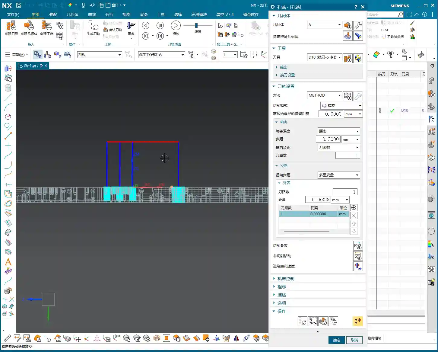
    Remember this: When do we typically use the Surface Driven command? Mainly for machining undercuts! With standard 3-axis machining, vertical and small angled surfaces might be manageable. However, when you encounter large angled surfaces or features with undercuts at the bottom, the tool is prone to tool deflection or interference. This is when you need to use Surface Driven. It allows you to use the side of the tool for machining, perfectly avoiding interference.

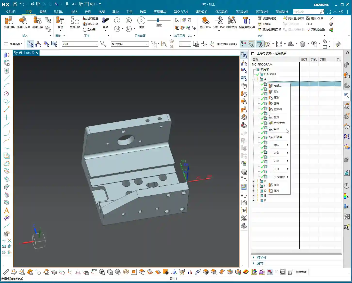
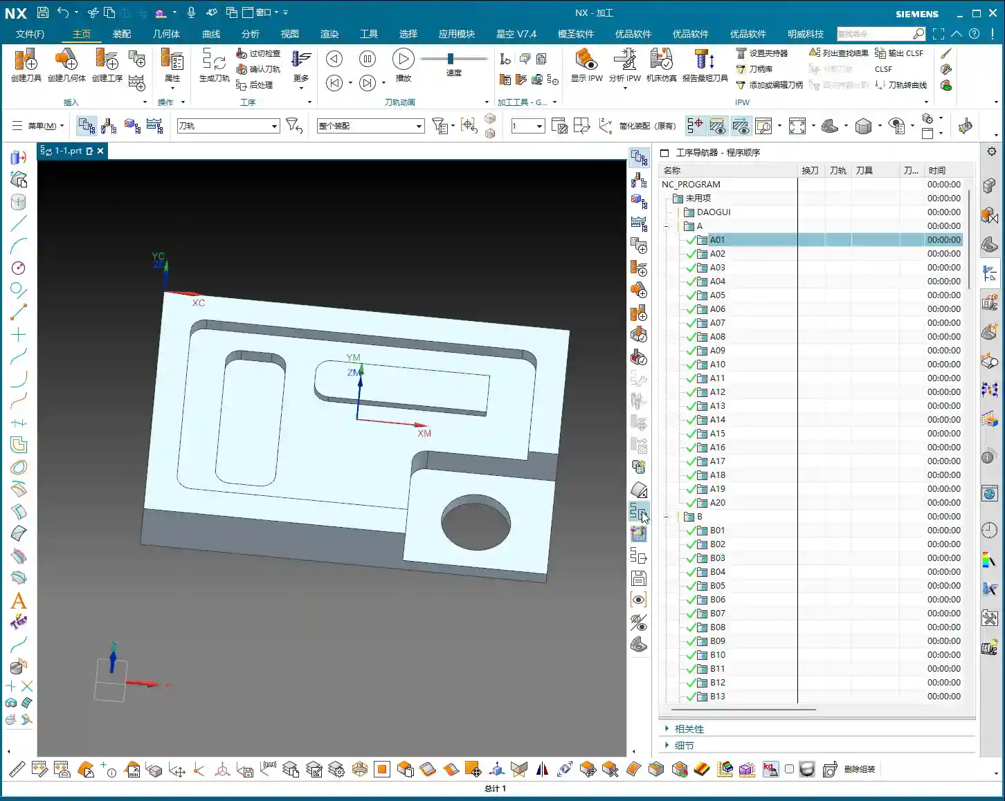
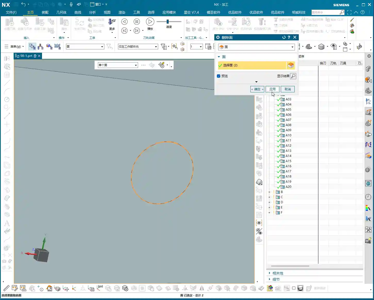
    Model Preprocessing: Proper Preparation Is Key

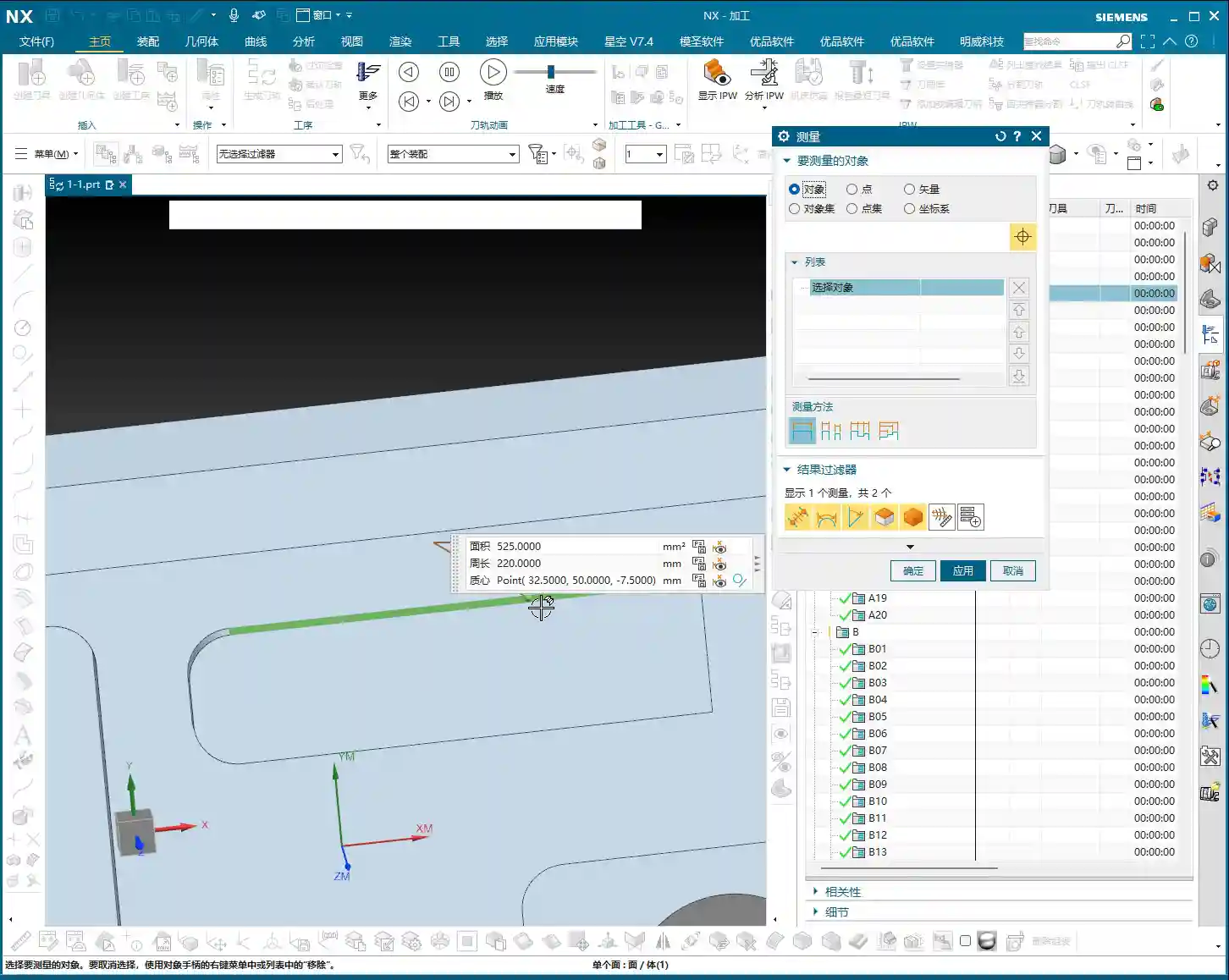
    Before you start machining, the model must be cleaned up first! I’ve said it countless times: Seal or delete all those small holes, chamfers, broken faces, and through holes on the surfaces you intend to machine! Don’t be lazy! These tiny, fragmented features will cause issues for your toolpath generation, potentially leading to unnecessary pauses or even errors. Just like I demonstrated earlier, if the model precision isn’t good, even deleting those small chamfers can be a hassle. It’s best to handle this during the CAD phase, or copy the part to another layer, keeping only the faces to be machined and ensuring they are clean. Otherwise, you might see no issues in the software simulation, but once it’s on the machine, the toolpath will be erratic, the cutting sparks will look wrong, and efficiency will be impossible!

    Tooling and Parameters: A Seasoned Engineer’s Choice

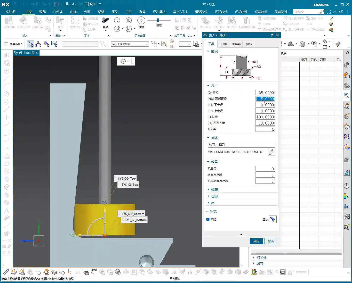
    T-Slot Cutter / Dovetail Cutter: The Ultimate Tool for Undercut Machining

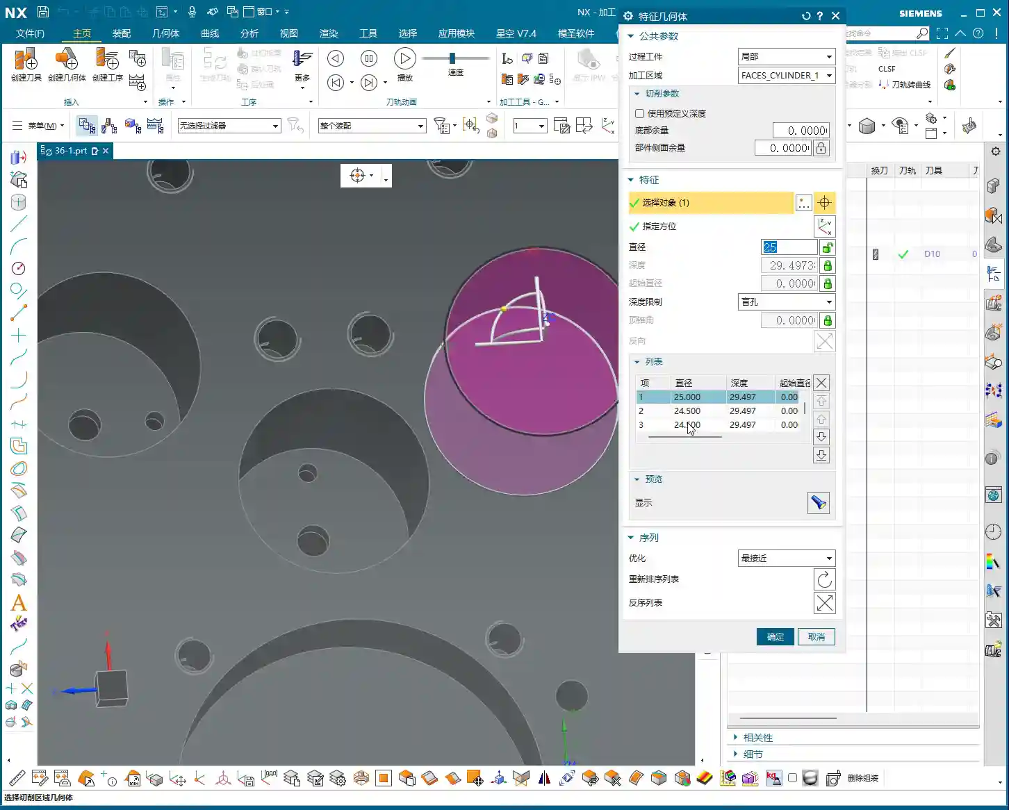
    For undercut machining, tool selection is paramount. Typically, we use a T-slot cutter (or similar dovetail cutter). The characteristic of such tools is a large head diameter with a slender neck, making it easy to reach into undercut areas. Parameter settings must be precise:

    • Tool Diameter (D): For example, 25mm. This is the diameter of the tool’s largest cutting portion.
    • Neck Diameter (d): For example, 10mm. The neck must be thinner than the head to fit into the undercut.
    • Bottom Radius (R): For example, 5mm. This is the radius of the tool’s bottom corner, directly affecting the resulting fillet radius after machining.
    • Bottom Length: This is also very important. For instance, here it is 10mm (composed of two 5mm radii). This length must ensure that the tool’s effective cutting portion can cover the machining area, while simultaneously preventing interference between the tool neck or shank and the workpiece.

    Remember, don’t just rely on software parameters. Always measure the actual tool before mounting it on the machine, especially the effective flute length and corner radius. Even a slight discrepancy could lead to tool deflection or improper machining, potentially scrapping the part!

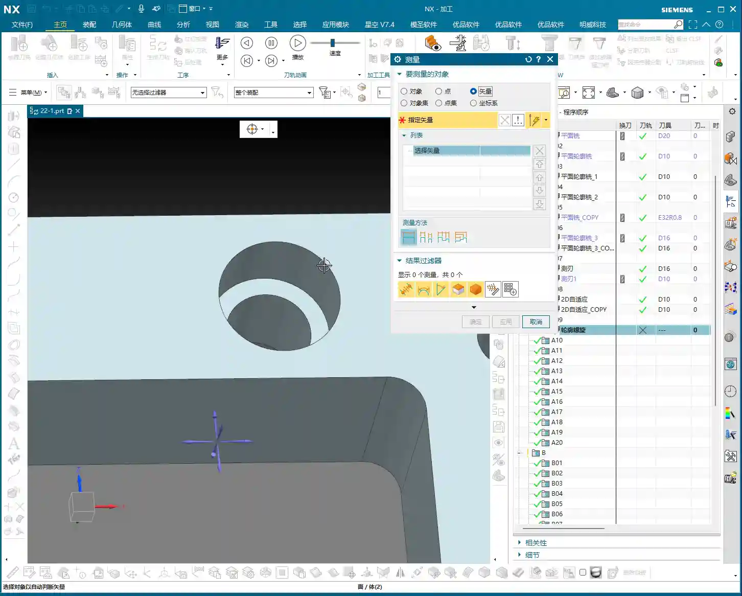
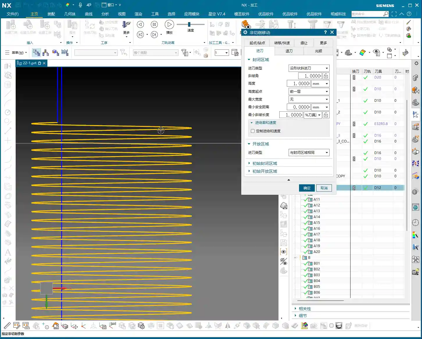
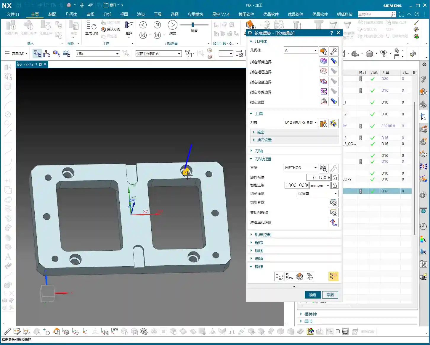
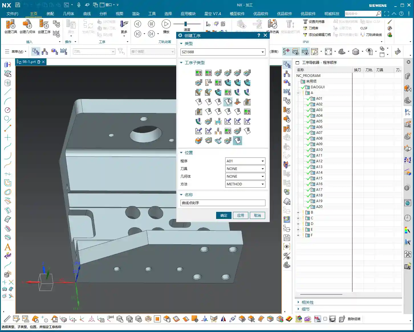
    Coordinate System and Cutting Method

    I won’t elaborate on the coordinate system; it’s business as usual. Just create one anywhere near the machining area, as long as it’s valid and provides proper positioning. As for the cutting method, we generally default to selecting “Towards Cut Stock.” This is Siemens NX’s default option, the most commonly used, and suitable for most situations. If your part is exceptionally complex, you might need to consider other cutting methods, but we can discuss those later.

    Summary: Pitfall Avoidance Guide

    Listen closely; these are hardcore pitfall avoidance tips compiled from my 15 years of experience as Master Wang:

    • Model First, Clean Surfaces Are King: For any complex surface machining, model cleanliness is paramount! Small features and discontinuous faces are “cancerous” for toolpath generation; they will make your toolpaths uneven, and can even lead to chip re-cutting or tool alarms. Spending time cleaning the model upfront will save you several times that in debugging later.
    • Tool Matching, No Brute Force: Not just any tool can machine an undercut. T-slot cutters and dovetail cutters are your first choice. Parameters must be precisely calculated, with key focus on neck clearance and effective cutting length. Choosing the wrong tool is like running headfirst into a wall.
    • Be Observant, Pay Attention to All Cues: Don’t just stare at the computer simulation; that’s only theoretical. During actual cutting, observe the sparks, listen to the sound, and feel the vibration. Incorrect spark color, harsh sounds, or abnormal vibration are all the machine “talking” to you. Stop the machine immediately to inspect and prevent major accidents.
    • Precision Calibration, Adapt and Overcome: Machine accuracy will never be perfect. When encountering precision issues of ±0.005mm, don’t just complain. Try to compensate through process compensation, adjusting toolpath strategies, or even localized manual finishing. High precision is achieved through meticulous effort and fine-tuning.
    • Cost Efficiency, Ingrained in Your Core: All toolpath optimizations ultimately aim to improve efficiency and reduce costs. Every rapid move is burning money; every defective part is wasting time. When designing toolpaths, always think about how to reduce non-cutting moves, optimize feed rates, and extend tool life. This is not just about technique; it’s the crystallization of experience and wisdom.

    👤 About the Author:
    The author is a veteran CNC machining professional with 15 years of industry experience, specializing in UG NX programming. This article is an original work representing personal practical insights.

    ⚠️ Copyright Notice: Unauthorized reproduction or distribution without prior communication is strictly prohibited.

  • Siemens NX Hole Milling Operation: Master Wang’s Hands-on Guide to Feature Geometry Setup and Precis

    📝 Key Takeaways: Master Wang explains the Siemens NX Hole Milling operation and feature geometry. The tutorial emphasizes a 2D machining perspective, detailing common operations like Hole Milling and Drilling. It highlights WCS coordinate system establishment, hole dimension verification, and deeply analyzes the “Specify Feature Geometry” function. Master Wang teaches how to flexibly adjust parameters like diameter and depth from automatic to “User Defined,” and combines this with practical machine operation experience, emphasizing the importance of avoiding overcutting and recognizing cutting sparks. A practical pitfall avoidance guide is included to help you precisely control hole machining in Siemens NX.

    Master Wang’s Talk: The Ins and Outs of Hole Machining

    Alright apprentices, listen up! Today we’re diving deep into hole machining in Siemens NX. This operation might seem simple, but there’s a lot more to it than meets the eye, especially the practical tricks that textbooks don’t teach. You’ll want to pay close attention. We’ll start with the most common Hole Milling operation and its feature geometry. Remember, for now, we’re sticking to 2D machining. Forget about fancy 3D stuff for a moment; let’s build a solid foundation first!

    The Hole Machining Family: Common Operations at a Glance

    There are quite a few operations in NX that deal with ‘holes,’ so let me break them down for you. These are the ones we commonly use in the shop, mostly 2D operations. Understand these first, and then we’ll go deeper:

    • Hole Milling: This is today’s main topic, primarily used for milling holes. It’s highly efficient, especially suitable for machining larger diameter holes.
    • Spot Drilling: Used for creating a center dimple to accurately position the drill for subsequent drilling, ensuring the drill doesn’t wander.
    • Drilling: Directly drilling holes with a drill bit. This is the most fundamental hole machining method.
    • Tapping: For machining threaded holes. This requires extremely precise coordination between spindle speed and feed rate; one mistake and the part is scrap.
    • Centering: Another type of positioning, sometimes used with spot drilling, chosen based on the specific workpiece and precision requirements.
    • Boring: Using a boring bar to enlarge and correct hole diameters, improving accuracy and surface quality. This is key for achieving high-precision holes.
    • Reaming: Using a reamer to fine-tune hole diameters and surface roughness, further enhancing precision and finish.
    • Deep Hole Drilling: A specialized machining strategy for deep holes, requiring consideration of chip evacuation, cooling, and preventing drill runout.
    • Helical Milling: Also known as helical interpolation, using an end mill to machine holes with a helical plunge, resulting in stable cutting and good chip evacuation, suitable for hard materials or large holes.

    As for things like 3D solid contours, 3D chamfering, or 3-axis deburring, don’t rush into those yet. They’re advanced techniques and not used as frequently. We’ll cover them separately if the opportunity arises. For now, focus on mastering these fundamental, commonly used operations!

    Workpiece Preparation: Coordinate System and Hole Dimension Verification

    Before you even think about machining, get your workpiece and coordinate system sorted. This is the absolute first step on the shop floor, and it’s no different in NX.

    Establishing and Positioning the Coordinate System

    In Siemens NX, we first create the Work Coordinate System (WCS). Listen closely, this WCS is as critical as tool offsetting on the machine. It dictates the starting point and direction for all your toolpaths. Typically, we set the WCS origin at the center of the workpiece, or at a reference point that’s easy for tool offsetting. I personally prefer to have the Z-axis pointing upwards, in the direction of our tool feed. It looks right and reduces errors. Don’t underestimate this small habit; it can save your skin when it matters!

    Once the WCS is established, you need to verify it. Even though NX offers simulation, us veteran machinists live by ‘seeing is believing!’ It’s like how you always do a dry run after tool offsetting to confirm clearance. Make it a habit to ensure the WCS positioning is logical to prevent unexpected issues during machining.

    Hole Dimensions: Eye it, Measure it, Know it Cold

    Before machining, you need to be intimately familiar with the holes you’re going to work on. In NX, you can measure the hole diameter and depth. For example, as mentioned, holes might measure Ø32 or Ø20.5. Don’t just rely on the drawing; check the actual model. Are multiple holes symmetrical? Are all dimensions consistent? This is like when you get a new part; you first run a caliper over it to spot any obvious issues. Sometimes there can be ‘hidden traps’ between the design drawing and the actual model.

    Core: Hole Milling Operation and Feature Geometry Explained

    Alright, preparation is complete. Let’s get hands-on with the “Hole Milling” operation.

    Quick Start: Hole Milling

    To perform hole milling, simply double-click the “Hole Milling” operation in NX. Then, in the pop-up window, you need to create a geometry feature, such as selecting the default “A” or your custom geometry. This step tells NX which area you intend to machine. The operation itself is very straightforward, unlike some older operations with tedious steps.

    Specifying Feature Geometry: Selecting the Right “Target” is Key

    Listen closely, this is critically important! After entering the Hole Milling operation, you’ll see an option called “Specify Feature Geometry.” Click on it, and NX will prompt you to select the holes you want to machine. This is like standing at the machine and clearly telling the machinist, “Drill this hole, bore that one.” Whichever hole you select, NX will machine that hole. You can select them individually or batch-select multiple holes. Once selected, NX will automatically identify the diameter and depth of these holes.

    • Stock Settings: For now, we can skip options like “Process Tolerance,” “Trim Stock,” or “No Stock.” Stock allowances can be uniformly adjusted in more advanced parameter settings, so there’s no need to fiddle with them here every time. “No Stock” here simply means we generally don’t apply additional stock settings in this particular dialog.
    • Key Information: Once you select the hole, NX will automatically display its diameter (e.g., Ø20.5mm) and depth (e.g., 29.4999mm). These two parameters are the most critical data for hole machining, and you must know them inside out!

    After selecting the holes and a suitable tool, simply generate the toolpath, and a basic hole milling program is ready. Isn’t that simpler than you thought? The key is to select the correct geometry, and NX automatically determines most of the parameters for you.

    Advanced: Flexible Adjustment of Hole Parameters and Precision Control

    While default parameters are convenient, as machinists, we must have the ability to adjust and control them. This is especially true when dealing with non-standard parts, special materials, or when precision issues arise.

    Modifying Hole Diameter: From “Automatic” to “User Defined”

    You might notice that, by default, NX’s automatically identified hole diameter and depth cannot be directly modified; they appear “grayed out,” preventing input. Listen up, this isn’t NX stopping you from making changes; it simply thinks it has already determined the correct values for you. But if we need to make an adjustment, we have to tell it, “We’re taking control.”

    To modify the hole diameter, you must change the corresponding “Parameter Definition Method” or similar option (referred to as “decimal” in the audio, but usually a dropdown menu in actual operation) from “Automatic” to “User Defined.” Once set to “User Defined,” you can freely input your desired diameter.

    • Practical Example: For instance, changing a Ø20.5mm hole to Ø25mm. NX won’t throw an error, but when you generate the toolpath, you’ll see obvious “overcutting.” At this point, don’t just rely on software simulation; you need to know that on a real machine, one cut like that, and the part is scrap! This scenario can easily lead to excessive Depth of Cut (DOC) or even scrap the part directly. Don’t assume there’s no problem just because the software doesn’t flag it; that’s deceptive!
    • Flexible Adjustment: You can decrease the diameter to Ø20mm or increase it to Ø50mm, and NX will generate the toolpath according to your input. This is particularly useful when dealing with non-standard holes, irregular holes, or when needing to leave stock for finishing passes. However, you must be absolutely clear in your mind whether the modified dimension matches your tool and meets your process requirements.

    Adjusting Hole Depth: Precise Control for Deep Hole Machining

    Similarly, hole depth can also be flexibly adjusted. For example, you can set the depth of the first hole to 10mm, the second to 20mm, the third to 50mm, or even a deeper 100mm. This is crucial for machining multi-step holes, blind holes, or holes with varying depth requirements. Depending on material properties and tool conditions, we sometimes employ strategies like layered machining or pecking for chip evacuation, and flexible depth control is fundamental to implementing these strategies.

    Batch Modification: Efficiency is King

    If you have multiple holes of the same size that need adjustment, there’s no need to change them one by one. In the “Specify Feature Geometry” interface, you can hold down the Ctrl key to select multiple holes, or drag-select multiple holes, then change their “Parameter Definition Method” to “User Defined” all at once, and finally input your desired diameter or depth. This is a powerful trick for boosting efficiency. In our machining world, time is money, so save every step you can!

    Master Wang’s Practical Secrets: Fine-Tuning Dimensions and Tolerances

    Sometimes, when you encounter precision issues at the ±0.005mm (approx. 0.0002 inch) level, software alone won’t cut it. That’s where experience comes in! For example, machining aluminum versus titanium alloys – their thermal expansion coefficients differ, so cutting parameters and stock allowances must be adjusted. If a hole’s diameter is slightly off, you can achieve the correction by modifying tool compensation, or by fine-tuning the diameter of this feature geometry within Siemens NX. But remember, such fine-tuning must be built upon a deep understanding of material characteristics, tool wear, and machine accuracy. Don’t just rely on software simulation; you need to observe the cutting sparks, listen to the cutting sound, and feel the part. Those are the true skills!

    Summary: Pitfall Avoidance Guide

    • Pitfall 1: Blindly trusting default parameters. NX’s automatically identified parameters are based on the model, but they may not always align with your actual machining requirements. Especially for hole diameter and depth, always verify against the print and process specifications, and modify manually when necessary.
    • Pitfall 2: Failing to verify after modifying parameters. After changing diameter or depth, always regenerate the toolpath and perform simulation verification. More importantly, you must be mentally prepared and understand whether this modification will lead to overcutting, tool breakage, or dimensional deviations on a real machine. Just because the software doesn’t throw an error doesn’t mean the machine won’t!
    • Pitfall 3: Neglecting precise positioning of the coordinate system and workpiece. The accuracy of all hole machining operations relies on an accurate WCS. If the WCS isn’t correctly set, all subsequent holes will be off, the part will be scrapped, wasting both time and material.
    • Pitfall 4: Disregarding material characteristics. Different materials (from common aluminum to titanium alloys, high-temperature nickel-based alloys) have vastly different cutting parameters, tool selections, and heat treatment distortion tendencies. These factors must be fully considered during machining, for instance, for materials sensitive to thermal deformation, layered feeds and cooling methods must be accounted for.
    • Pitfall 5: Only focusing on the toolpath and ignoring cutting sparks. No matter how realistic Siemens NX simulation is, it’s still virtual. To truly judge the machining status, you need to rely on your eyes and ears. Spark color, chip formation, and tool sound – these are the machine “speaking.” An experienced machinist can discern issues like excessive Depth of Cut (DOC) or chipping from these details.
    • Pitfall 6: Fearing user-defined parameters. Many beginners are afraid to change automatic parameters to user-defined, thinking it leads to errors. But to become a master, you must grasp this ability for flexible adjustment. While ensuring safety, try more, learn from your experiences, and only then can you truly master Siemens NX.

    Alright, that’s it for today’s lesson. Go home and digest all of this. Get hands-on and practice; you won’t learn just by listening!

    [EXCERPT]
    Master Wang explains the Siemens NX Hole Milling operation and feature geometry. The tutorial emphasizes a 2D machining perspective, detailing common operations like Hole Milling and Drilling. It highlights WCS coordinate system establishment, hole dimension verification, and deeply analyzes the “Specify Feature Geometry” function. Master Wang teaches how to flexibly adjust parameters like diameter and depth from automatic to “User Defined,” and combines this with practical machine operation experience, emphasizing the importance of avoiding overcutting and recognizing cutting sparks. A practical pitfall avoidance guide is included to help you precisely control hole machining in Siemens NX.

    👤 About the Author:
    The author is a veteran CNC machining professional with 15 years of industry experience, specializing in UG NX programming. This article is an original work representing personal practical insights.

    ⚠️ Copyright Notice: Unauthorized reproduction or distribution without prior communication is strictly prohibited.

  • Siemens NX Contour Spiral Milling In-Depth Analysis: From Closed Paths to Collision-Free Retraction,

    📝 Key Takeaways: **

    Siemens NX Contour Spiral Milling: A Practical Guide

    Listen up, fellas! I’m Master Wang. Today, we’re diving into contour spiral milling…

    Listen up, fellas! I’m Master Wang. Today, we’re diving into contour spiral milling in Siemens NX. This feature gets a lot of use on the shop floor. Don’t let its similar interface to standard plane contour milling fool you; the real intricacies aren’t always clear in textbooks. With 15 years of hands-on experience, I can tell you: use spiral milling right, and you’ll double your efficiency; mess it up, and you’ll be dealing with **tool rubbing**, scrapped parts, and more!

    Contour Spiral Milling: Practical Fundamentals

    Within plane contour milling, there’s a function called “Contour Spiral.” Simply put, it’s for **spiral milling**. While it looks quite similar to conventional plane contour milling, its core requirements and application scenarios are distinctly different.

    Core Concept: Spiral Machining and Closed Contours

    First, remember this: the core requirement for spiral machining is that the machining contour must be closed! Just like drilling or pocket milling, you need to define a complete boundary. If you select only a single line, an open corner, or even an unclosed contour, spiral machining will fail. The program might generate toolpaths, but running it on the machine will certainly lead to issues because the tool won’t know where to **stepdown** spirally and might wander erratically. External contours, as long as they are fully closed, can also be processed with spiral milling.

    Siemens NX Operation Path and Interface

    Head directly to “Insert” -> “Operation” to find “Contour Spiral.” Once you click in, you’ll notice its main interface is almost identical to plane contour milling, with mostly similar parameter options. But don’t be fooled by appearances; subtle adjustments here determine machining quality and efficiency.

    Workpiece Measurement and Tool Selection

    Let’s say we need to machine a 20mm diameter hole (10mm radius). Tool selection here requires careful consideration. If you use a D12 end mill, it can efficiently mill out the hole within a single spiral path. This isn’t random tool selection; it must be based on the hole diameter and stock allowance to ensure the tool can cut effectively, not just picking a small tool for easier path generation.

    The Secret of “Yellow Line Spiral”

    After program generation, you’ll see the toolpath simulation in Siemens NX, primarily composed of “yellow lines.” In Siemens NX, these yellow lines represent engaged cutting paths, meaning the tool is continuously cutting, moving spirally downwards, inwards, or outwards until it reaches the set **depth of cut**. This is somewhat similar to dynamic milling, both aiming to ensure continuous tool engagement, reduce air cuts, and boost efficiency.

    Key Parameter Tuning and Optimization

    The essence of spiral milling lies in the precise tuning of several key parameters. If these aren’t set correctly, you’ll face low efficiency at best, and scrap your workpiece at worst.

    The Art of the Ramp Angle

    In the “Non-Cutting Moves” options, there’s a crucial parameter called “Ramp Angle”. This angle dictates the aggressiveness of the tool’s spiral **stepdown**.
    * A larger Ramp Angle means greater axial material removal per pass (higher effective **Depth of Cut**). Theoretically, machining speed is faster, but cutting load is also higher, leading to quicker tool wear or even chipping.
    * A smaller Ramp Angle means less axial material removal per pass, resulting in a denser machining path, smoother cutting, and better surface quality, but it also takes longer.
    In practice, you need to adjust this flexibly based on material hardness, tool type, and workpiece precision requirements. For example, for contours with long perimeters, you should set a smaller **Ramp Angle**, such as 0.1 degrees, to ensure reasonable axial material removal per pass and stable cutting.

    Ramp Length and Tool Matching

    Another easily overlooked detail is “Ramp Length.”
    * If you’re using a solid carbide end mill (without inserts), setting a small ramp length, even 1%, is usually fine because its entire cutting edge can engage.
    * However, if you’re using an indexable insert tool, pay close attention! The bottom of the insert is non-cutting. If the ramp length is too small, the insert bottom can easily rub against the workpiece, causing friction and **chatter**. At best, this damages the tool; at worst, it causes chipping or even scraps the workpiece. In such cases, I usually recommend setting the ramp length to 50% of the tool diameter. If Siemens NX prompts that the program cannot be generated, it means your parameters are unreasonable, and the tool is highly likely to **rub** or **gouge** the material.

    Efficiency Secret for Multi-Hole Machining

    If you encounter multiple identical holes requiring spiral machining, don’t be foolish and create a program for each one individually. Siemens NX has a solution:
    1. Go into the “Part Boundaries” option.
    2. Select “Add New Geometries.”
    3. Change the selection type from “Face” to “Curve”.
    4. Then, sequentially select the inner contour curves of all holes that need machining.
    5. Click the middle mouse button to confirm, then click “OK” to generate the toolpath.
    This way, one program handles all holes, saving time and effort—that’s how we achieve efficiency!

    Scope of Application: More Than Just Round Holes

    Don’t assume spiral machining is only for milling round holes. As long as it’s a closed geometric shape, whether square, triangular, or even an irregular contour, you can use contour spiral machining. The key is:
    * It must be closed! If your contour is originally open but you want to use spiral machining, you’ll need to manually “extend” it to form a closed path. This prevents the tool from “air cutting” and ensures it quickly completes the extended portion.

    Summary: Pitfall Avoidance Guide

    Alright, here are the crucial points, learned through hard lessons:

    1. The contour must be closed! This is the foundation of spiral machining; misunderstand this, and you’re asking for trouble.
    2. Beware of spiral retract collision! This is the most common and dangerous pitfall. Especially when machining through holes, as the tool reaches the final **Depth of Cut**, the central slug (waste material) might drop. If the tool retracts along an arc (default setting), it will swing sideways. If the falling slug hasn’t fully detached, it could collide with the retracting tool! The result: tool chipping, scrapped workpiece, or even machine damage.
    * **Solution:** Always check the retract type in “Non-Cutting Moves.” Change the default “Arc Retract” to “Lift” (vertical retract). This way, after completing the cut, the tool will lift straight up vertically, avoiding potential falling slugs. Safety first! I usually set a 3mm lift; that’s generally sufficient.
    3. Ramp length must match the tool type! For indexable insert tools, provide sufficient ramp length (e.g., 50%); for solid carbide or custom-ground tools, it can be smaller.
    4. Adjust ramp angle according to contour perimeter! The longer the contour, the smaller the ramp angle should be to ensure stable cutting.
    5. Be flexible with stock allowance settings! While spiral machining is typically for **roughing**, if you aim for high precision or need to leave stock for a subsequent **finishing pass**, you must precisely set the stock allowance parameters. Don’t assume it’s **roughing** and completely omit stock, unless you’re sure a single pass is sufficient and meets precision requirements. This depends on your actual workpiece requirements and subsequent operations.

    Remember these points, and spend time observing the cutting sparks at the machine, not just relying on software simulations—practice makes perfect!

    👤 About the Author:
    The author is a veteran CNC machining professional with 15 years of industry experience, specializing in UG NX programming. This article is an original work representing personal practical insights.

    ⚠️ Copyright Notice: Unauthorized reproduction or distribution without prior communication is strictly prohibited.

  • Master Wang’s Guide: Analyzing Parts Before Programming in Siemens NX 1980

    📝 Key Takeaways: Master Wang demonstrates essential pre-programming part analysis in Siemens NX 1980. Learn to inspect dimensions, fillets, and slopes to develop robust, efficient machining strategies and prevent costly reworks.

    Hello everyone, I’m Master Wang. Starting from this lesson, we’ll officially delve into Siemens NX programming. Today, let’s talk about how to “see through” a part before programming to avoid detours!

    Step One: Understand Basic Part Dimensions and Raw Material Size

    Listen up! When you get a part, the first thing isn’t to rush to click the mouse, but to “measure its three dimensions”! It’s like knowing your clothes size; machining is the same.

    Measuring Finished Dimensions and Raw Material Size

    In Siemens NX, we need to use the “Measure Entity” function. Click it open, measure the part’s length, width, and height. For this example, the length is 270mm, the width is 180mm, and the height is 40mm. Keep these finished dimensions in mind. At the same time, you need to know the raw material’s size; this determines your roughing stock.

    Master Wang’s Tip: Don’t just rely on the software display. In actual machining, ensure your raw material has sufficient allowance. You don’t want to find out you’re short on material at the machine, or that the allowance is too large, leading to excessive air cutting time!

    Step Two: Detailed Inspection of Part Geometry (Fillets and Slopes)

    After measuring the overall dimensions, it’s time to act like a detective and thoroughly inspect every corner and edge of the part. Especially fillets and slopes, as they directly influence your tool selection and machining strategy.

    Analyzing Fillet Sizes

    We’ll use the “Geometric Properties” function to check fillets. For instance, if your fillet radius is R10, your tool selection needs careful consideration. Using a D20 (diameter 20mm) end mill to machine this fillet is perfectly fine; it will clear it precisely. Of course, a D16 or D10 tool can also be used, as long as the tool diameter is less than or equal to 20mm. But don’t even think about using a D1 tool; that’s just unrealistic. It’ll be incredibly inefficient and you’ll likely break the tool.

    So, the principle of tool selection is: it must be able to reach the desired feature while also considering efficiency and cost. Don’t use a cannon to kill a mosquito, nor a sewing needle to chisel a rock!

    Checking Side Wall Slope (Perpendicularity)

    Slope analysis is extremely important! Open the “Draft Analysis” function and carefully examine the side walls. If all side walls appear green, it means they are all vertical faces (straight walls), without any undercuts or tapers. This simplifies the part, allowing you to machine it directly with a standard end mill, without needing special processes. If you find any areas with incorrect colors, like red, there might be undercuts or sloped surfaces, and you’ll need to consider using ball end mills, tapered tools, or 5-axis machining.

    Remember: understand the part’s “temperament” to prescribe the right treatment, so you don’t get flustered at the machine.

    Step Three: Establish a Standardized Program Management Process

    After analyzing the part, we move on to programming. But programming isn’t random; it needs a method. Especially for beginners, a standardized program management process is crucial.

    Creating Operations in Sequence

    In Siemens NX, right-click on a folder -> Insert -> Operation. Pay attention here: operations must be created in the actual machining sequence. For example, roughing first, then semi-finishing, and finally finishing pass, from top to bottom, outside to inside. You can’t just jump to programming a specific hole because you want to machine it first; that will lead to big problems on the actual machine!

    Imagine this: you still have a lot of raw material on top that hasn’t been cleared, and suddenly you go to machine a small hole. Isn’t that just asking for a tool crash? So, roughing before finishing, outside before inside, face milling before hole drilling – these are fundamental principles. While we can be a bit more flexible during practice, on a real machine, not a single step can be wrong!

    Learning the Practical Use of Each Programming Command

    Our current learning focus is to understand how each programming command is used, such as Face Milling, Planar Profile, Cavity Milling, Depth Profile, Flow Cut, Curve Drive, and so on. Knowing their individual “personalities” and applicable scenarios will allow you to program with ease.

    Remember, these commands are like your toolbox. Understanding the purpose of each tool will make you a true “master operator”!

    Summary: Pitfall Avoidance Guide

    • Blindly starting is a major taboo! Always thoroughly analyze part geometry before programming, including dimensions, fillets, and slopes. Don’t overlook any detail.
    • Tool selection isn’t guesswork! Choose tools rationally based on fillet sizes and side wall characteristics, balancing machining efficiency and cost. Avoid using small tools for large tasks or large tools for small holes.
    • Program sequence is critical! During actual machining, strictly follow the “roughing before finishing, outside before inside” principle for operation arrangement to prevent tool crashes and ensure safe and efficient production.
    • Take detailed notes! Develop a good habit of recording the analysis results and tool selection strategies for each part, building your own machining experience database.