Tag: Siemens NX Programming

  • Siemens NX Multi-Operation Part Machining: Master Wang Guides You from Raw Stock to Finished Product

    📝 Key Takeaways: Master Wang explains practical Siemens NX multi-operation part programming, covering the full process from raw stock positioning and process planning to Face Milling, chamfering, pocketing, drilling, and post-processing. The discussion emphasizes Work Coordinate System (WCS) transformation, program optimization, tool selection, and Clamping strategies. He also shares real-world experience on avoiding common pitfalls, helping you boost efficiency, reduce costs, and master practical know-how “you won’t find in textbooks.”

    Listen up, young engineers! Today, Master Wang is taking you through multi-operation part programming. Don’t let this example part fool you with its simplicity; it’s a small bird with all its vital organs. We’re not just going to learn how to click around in NX; more importantly, we’ll understand the underlying process logic and machine tool behavior. This is the real expertise gained from hands-on experience in the field – you won’t learn this from any textbook.

    Our approach here is to go from raw stock to finished product, with every step carefully calculated. Today’s part is a typical example of multi-sided machining. Programming strategy, Work Coordinate System (WCS) transformations, and smooth operation transitions are all critical in real-world scenarios. Especially for those aiming for complex Surface Milling or 5-axis machining, if your fundamentals aren’t solid, everything else will be built on shaky ground! Siemens NX has a vast number of commands, so we can’t cover everything. We’ll focus on practical techniques that are useful, highly efficient, and cost-effective.

    Step One: Overall Planning and Process Decomposition

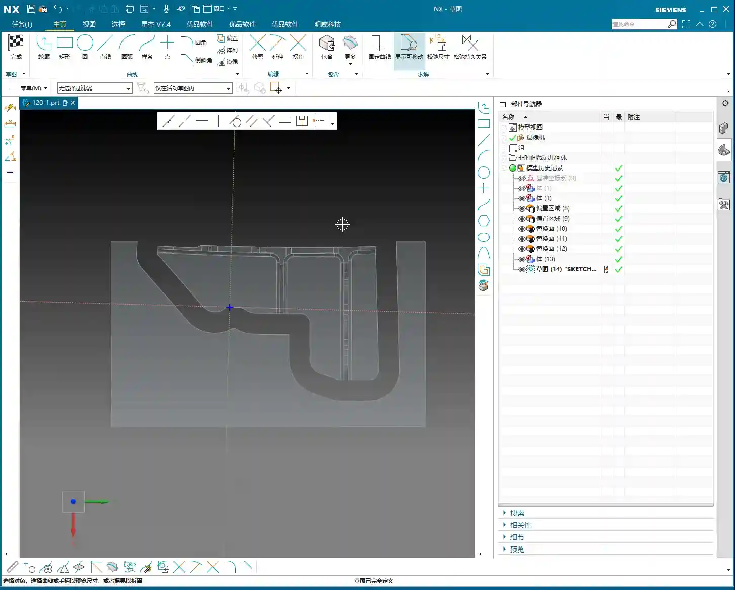
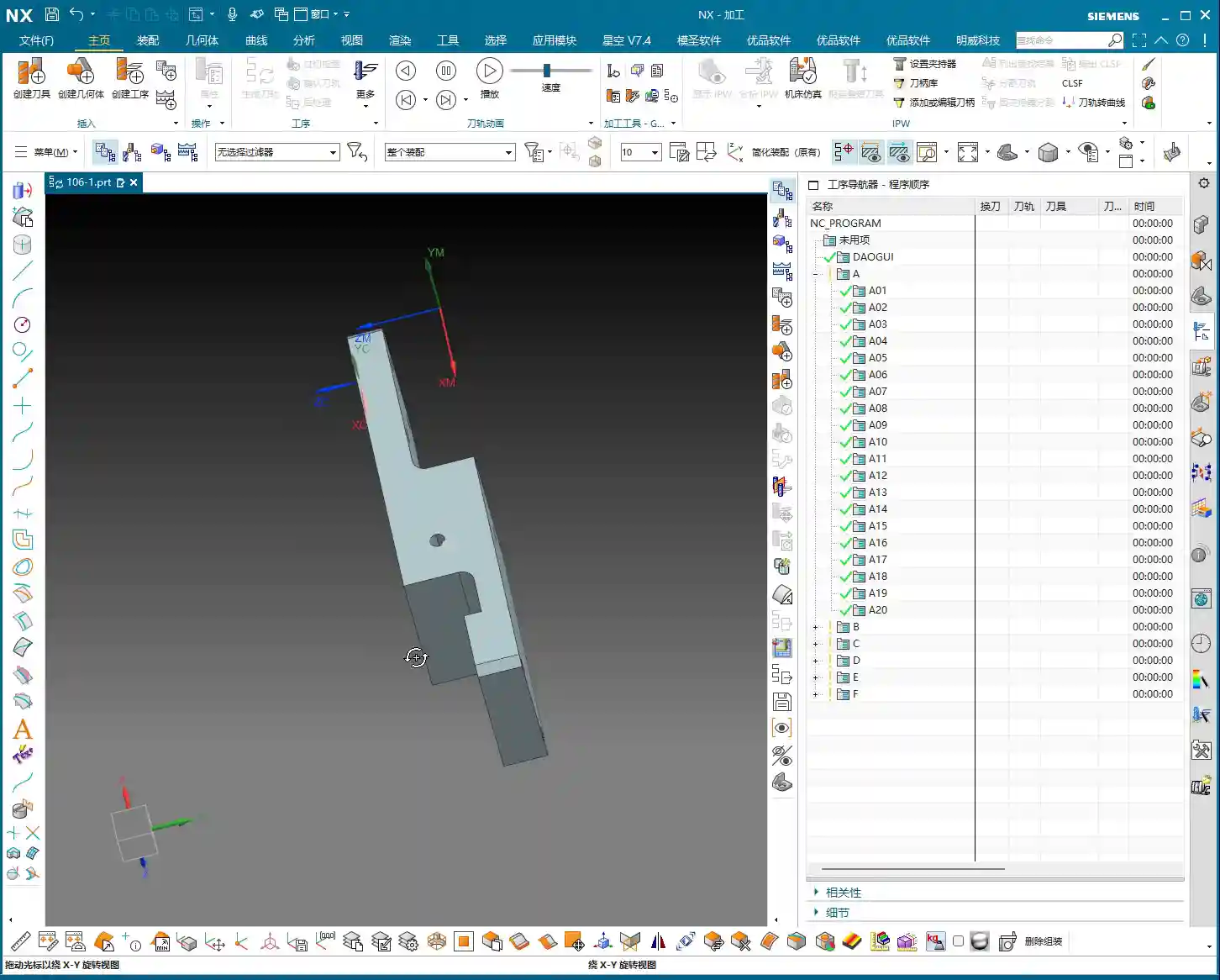
    When you get a new part, don’t rush into drawing or programming. First, you need to visualize its “past and future”: What material is it? What are the precision requirements? How will it be Clamped? What tools will be used? You need to think through all of these. For this part, we plan to complete it in multiple operations with multiple Fixturing setups.

    Clarifying the Machining Strategy: Never Fight Unprepared

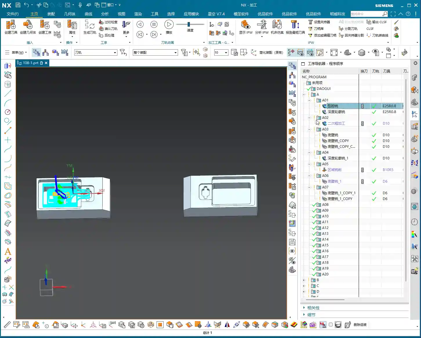
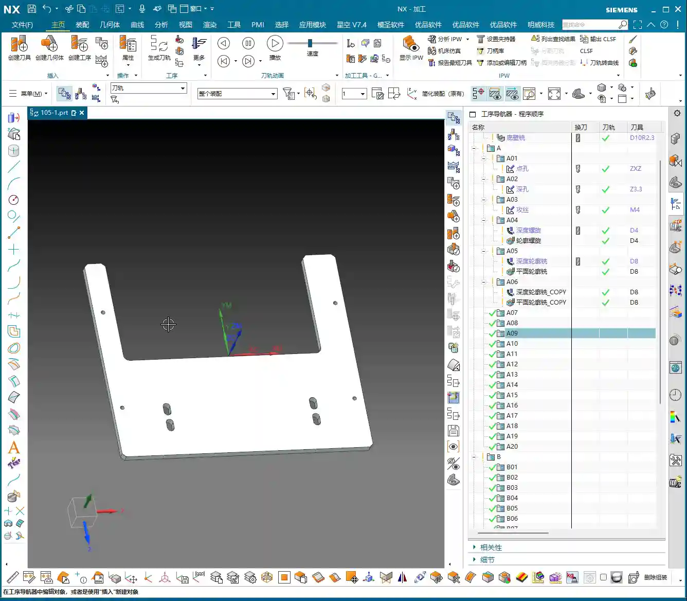
    Listen up, planning comes first. For this part, we’ll use three Work Coordinate Systems (WCS) – A, B, and C – to distinguish different machining faces. The specific steps are roughly as follows:

    • Operation A (First Face): Machine the front face first, establishing datums for the subsequent flip.
    • Operation B (Second Face): Flip the part over and machine the back face, again establishing datums.
    • Operation C (Third Face): Flip it again to machine the holes and pockets on the top or side.

    You need to think clearly about each step, otherwise, you’ll be scrambling, leading to scrapped parts or out-of-tolerance dimensions, which will cost you dearly.

    Raw Stock Positioning and Clamping Strategy

    The Clamping of the raw stock directly impacts machining accuracy and efficiency. For this part, we’ll first fixture one side for Roughing. Once the first side is machined, we then flip the part and re-clamp it. At this point, the new Clamping datum must be selected on the already machined surface from the first side, ensuring accurate datum transfer. While it might seem like just clicking in Siemens NX, on the machine, every detail – fixtures, parallels, clamps – must be meticulously considered.

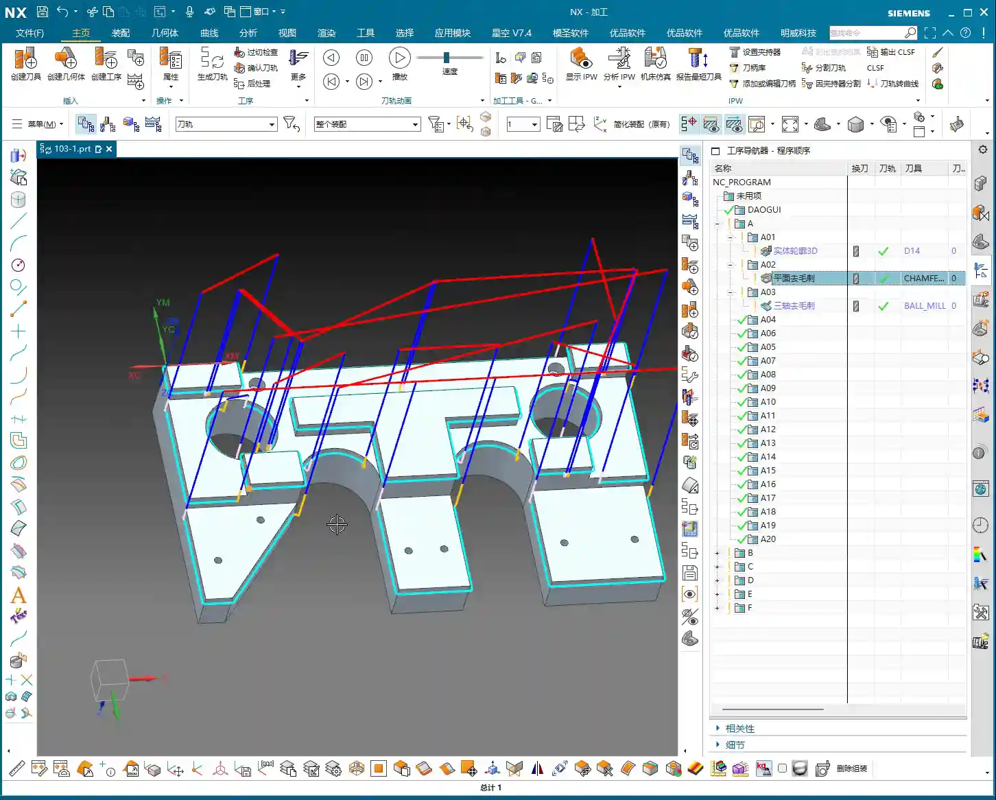
    Step Two: Front Face Machining (Operation A)

    This is our first machining face, primarily involving Face Milling, chamfering, and pocket Roughing. Don’t underestimate Face Milling; the flatness and surface finish directly influence the datums for subsequent operations.

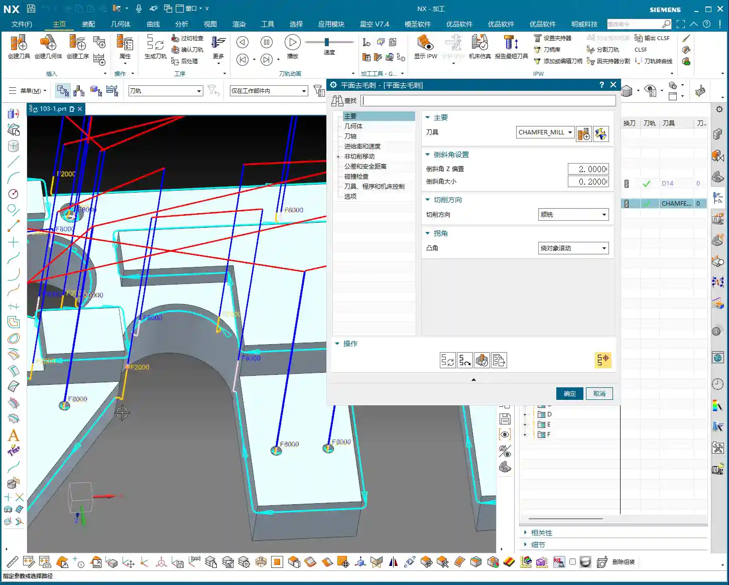
    Face Milling and Chamfering

    First, we’ll use a face mill to flatten the entire surface. The Depth of Cut (DOC) can be a bit larger, for example, 2mm, to get it done in one go. Remember, when programming, your entry and exit paths must be smooth; avoid sharp, right-angle turns, as that can lead to heavy tool engagement, which is bad for both the tool and the machine.

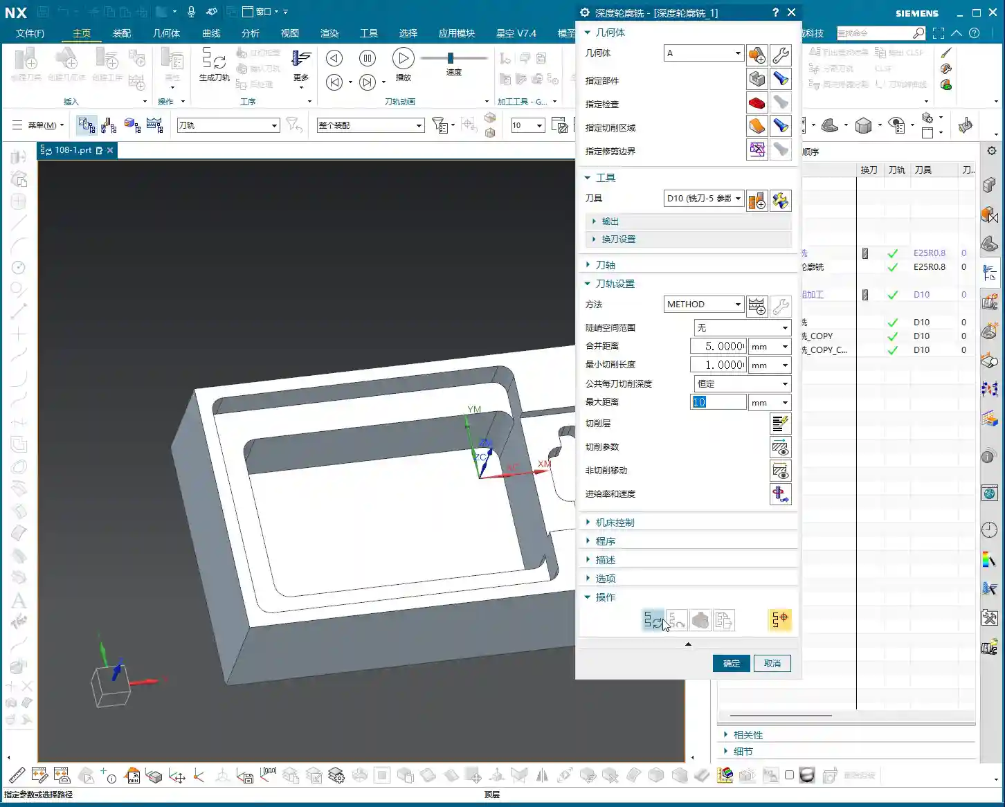
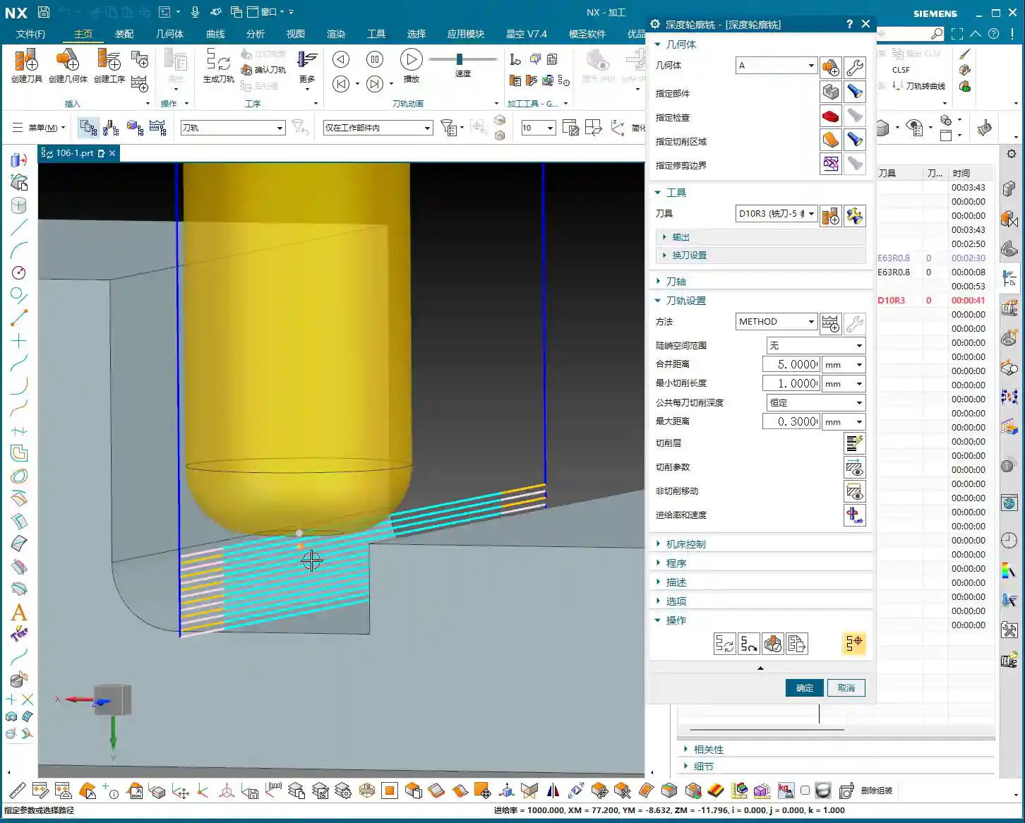
    Next is chamfering. This may seem like a minor detail, but its function is significant: it eliminates sharp edges, protects operators, and prevents part damage during handling. We’ll use depth milling, select these four corners, and set the Depth of Cut (DOC) to 50% of the tool diameter. That’s a solid approach.

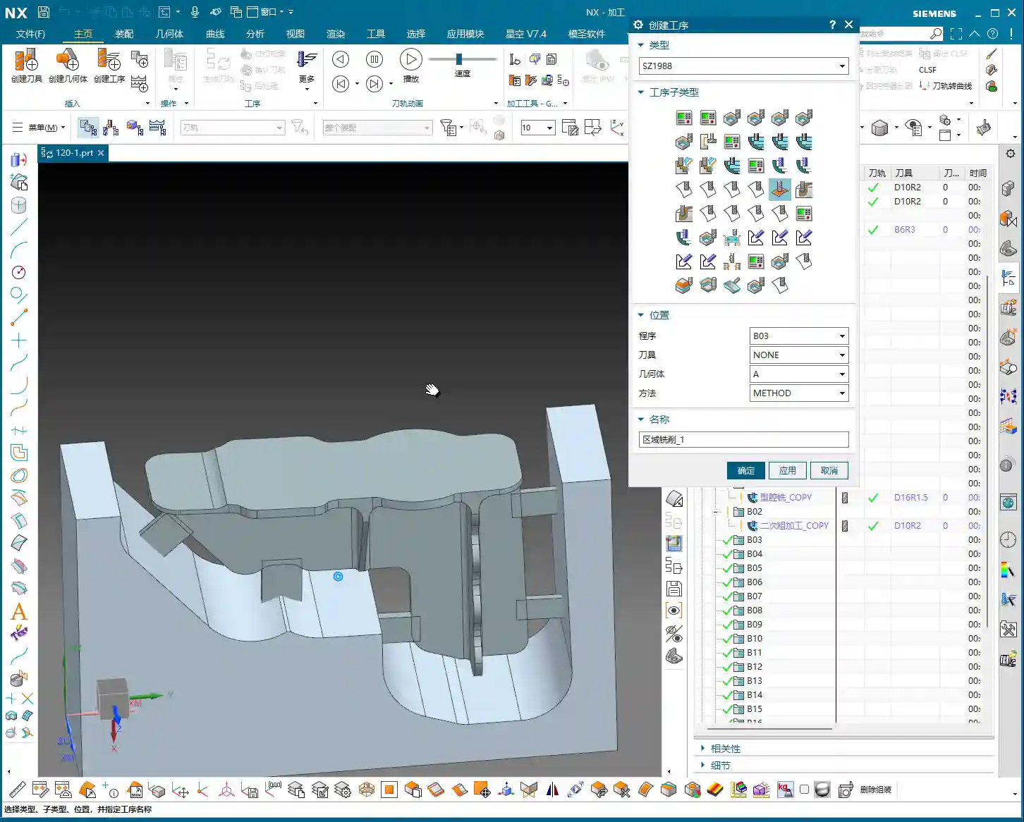
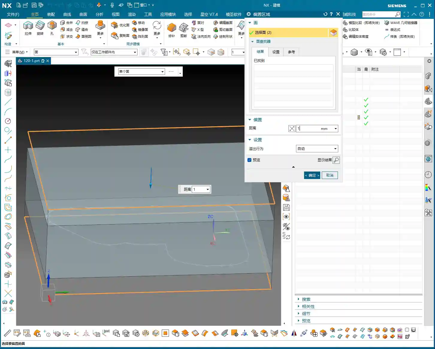
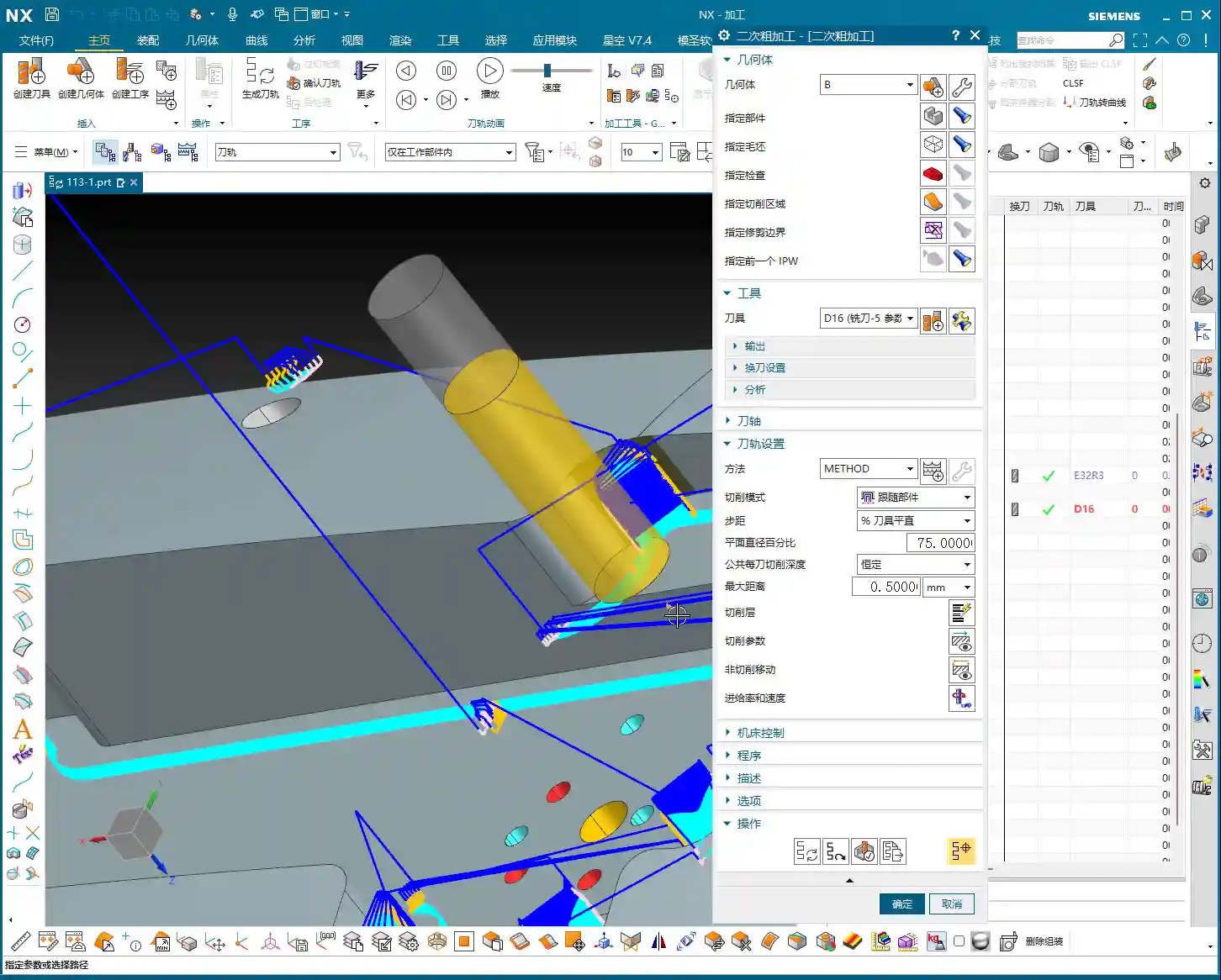
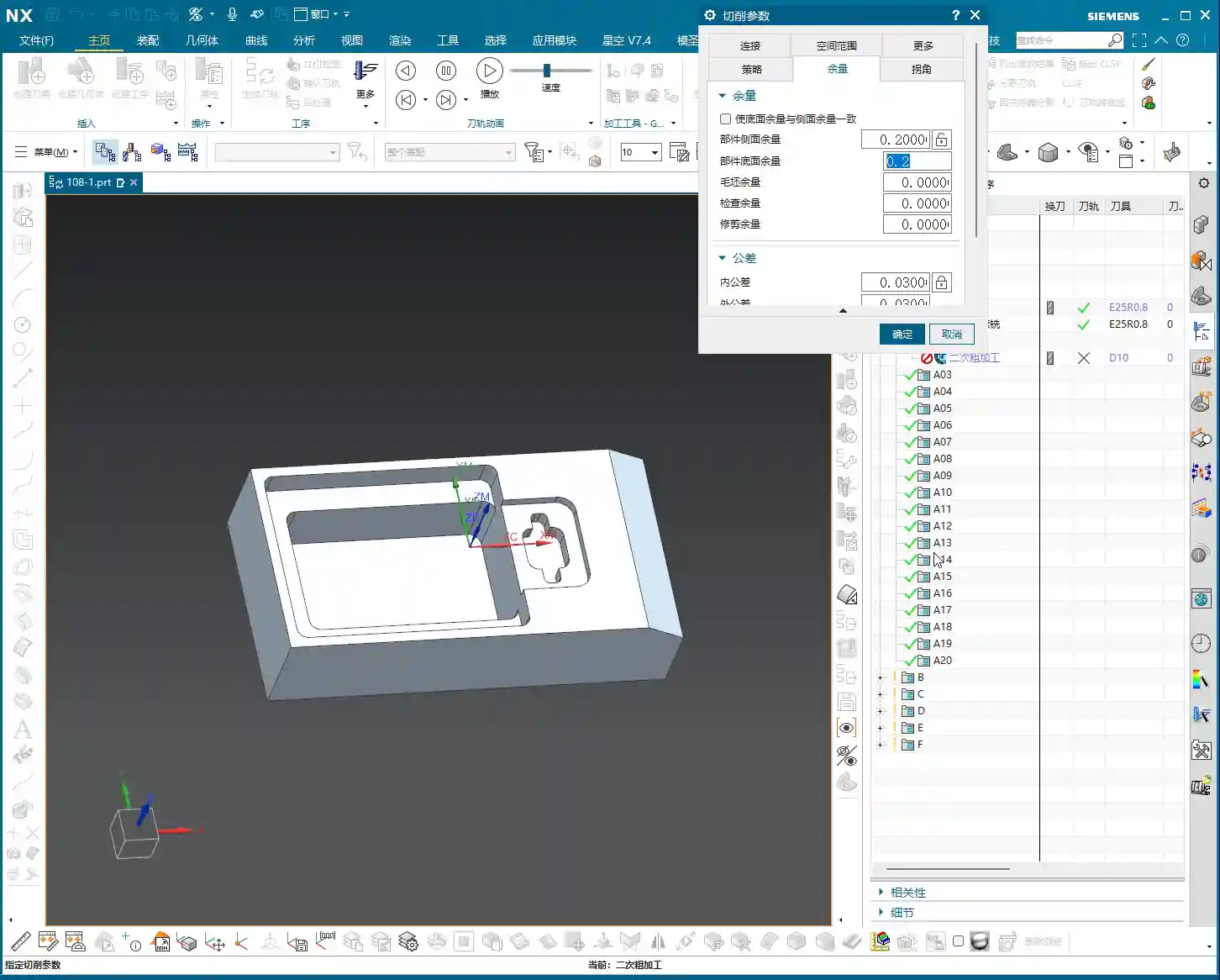
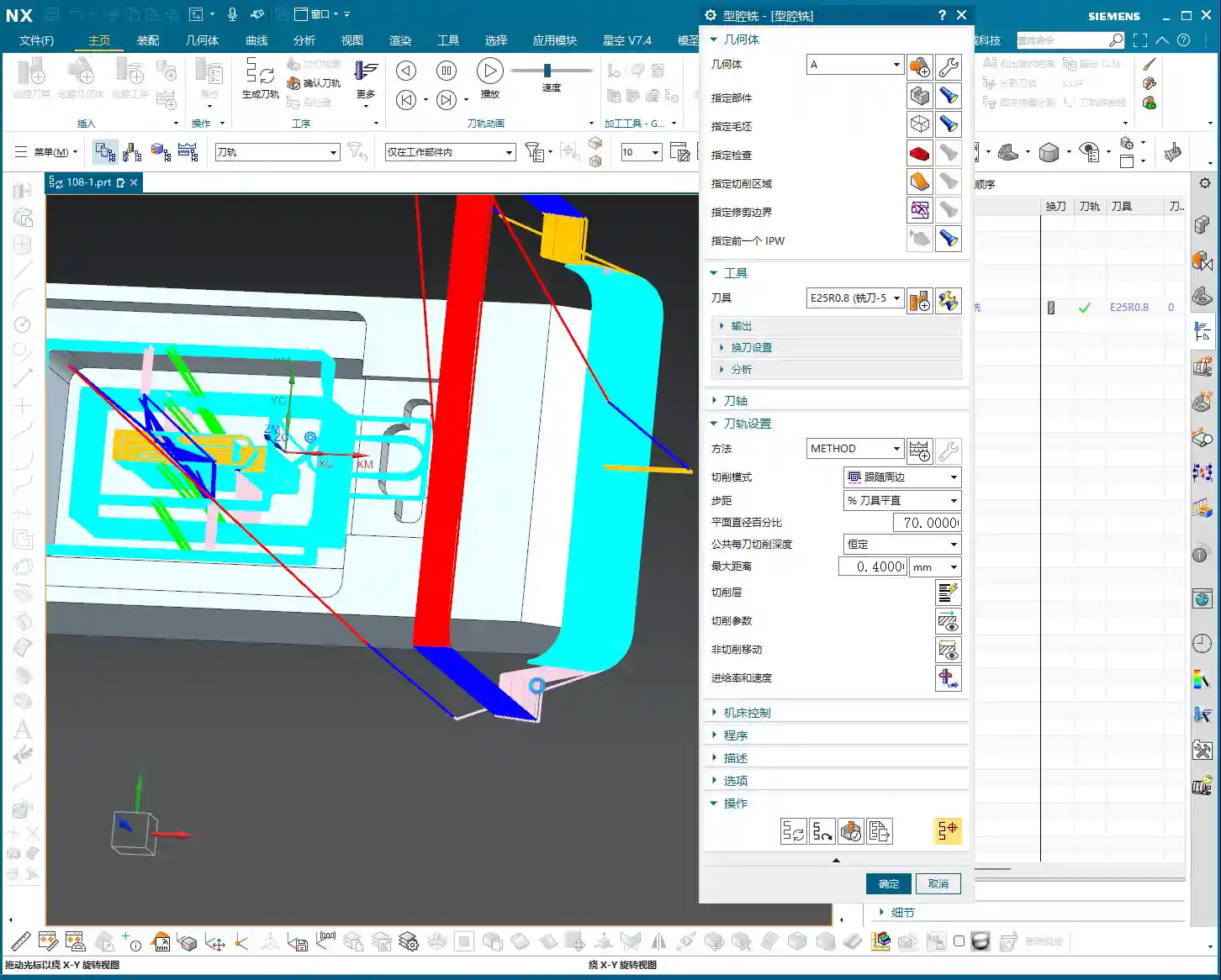
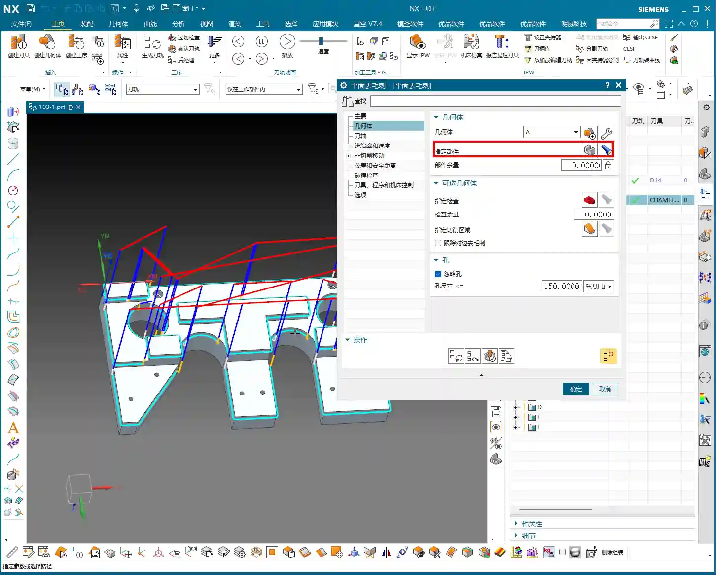
    Pocket (Cavity) Roughing

    Next is the Roughing of the internal pocket. For this, we’ll use a pocket milling operation. As for tooling, start with a larger tool to clear most of the material. The Depth of Cut (DOC) and feed rates must be determined by the material properties. For example, common aluminum can be machined faster, but titanium alloys and high-temperature nickel-based alloys require a more cautious approach to ensure chip evacuation and tool life.

    Master Wang’s Pro Tip: Don’t always aim for a single-pass solution; separating Roughing from Finishing is the golden rule. Roughing prioritizes efficiency, leaving sufficient material allowance; Finishing pass prioritizes accuracy and surface finish, so the cuts must be stable and slow.

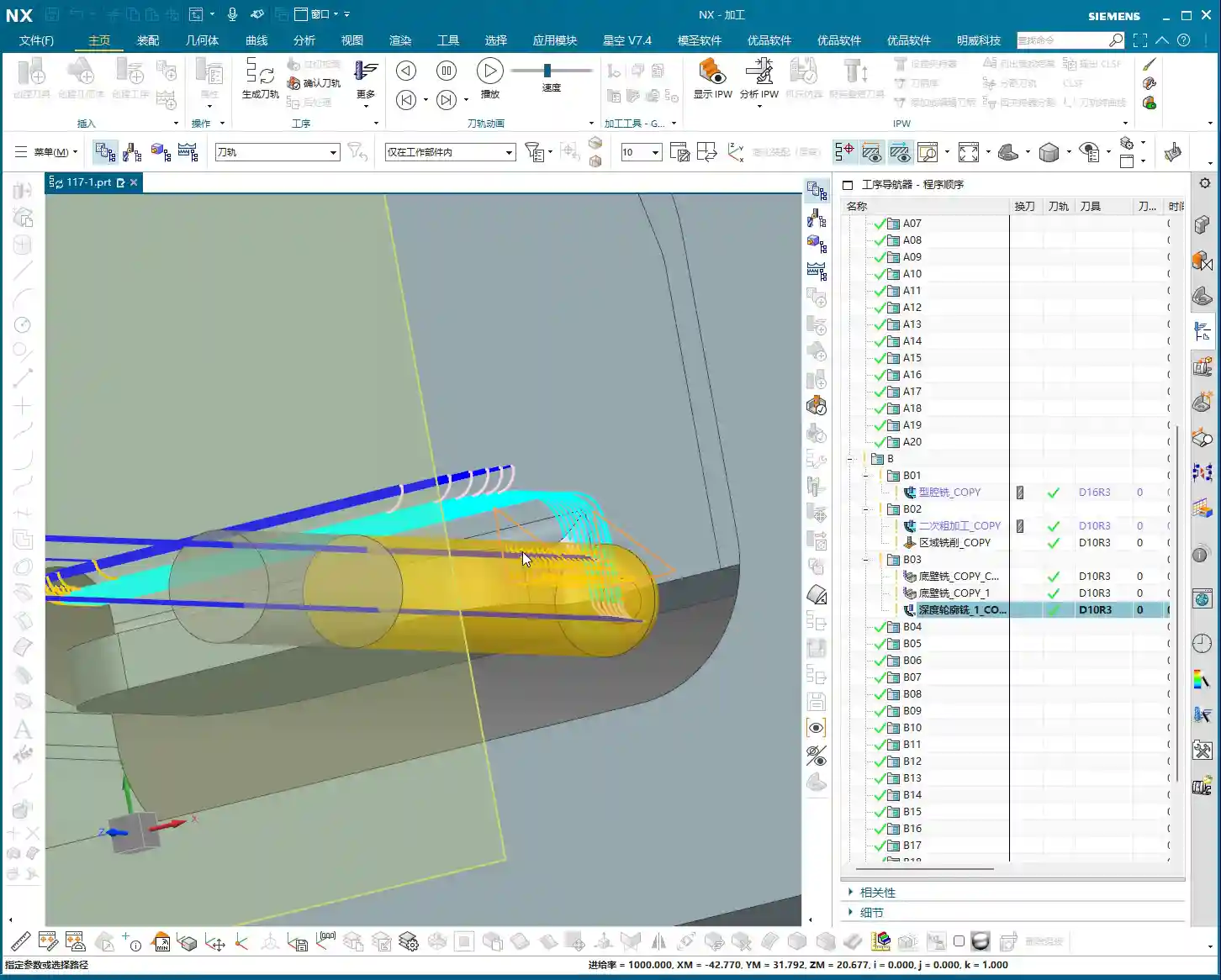
    Step Three: Back Face Machining (Operation B)

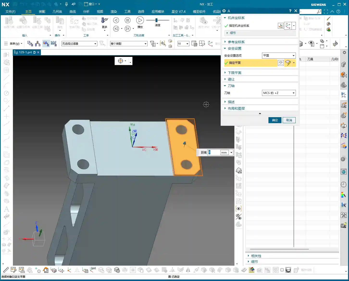
    Once the first face is done, we’re ready for flip-over machining. At this stage, Work Coordinate System (WCS) transformation is paramount; get it wrong, and all your previous efforts will be wasted.

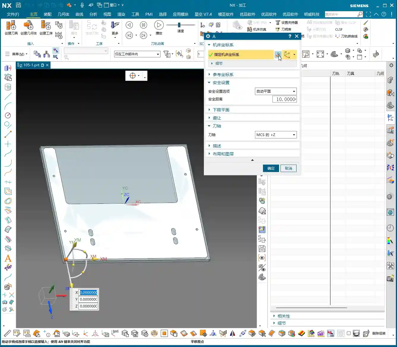
    Coordinate System Transformation: Flipping is Key

    Listen up, creating a new WCS (Coordinate System B) typically involves reversing the Z-axis direction and redefining the XY plane. The easiest method is to use an already machined feature as a reference for your new Work Coordinate System (WCS). For example, the face you just Face Milled on the first side becomes your Clamping datum for the second side. In Siemens NX, as long as you select the correct datum, the system will automatically help you with positioning, saving you time and effort.

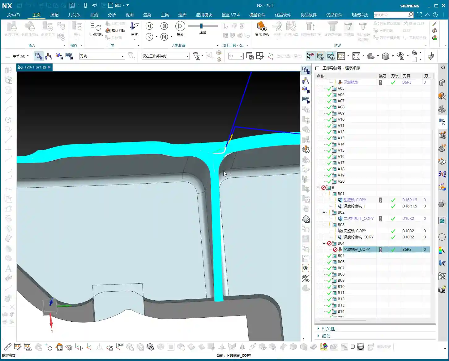
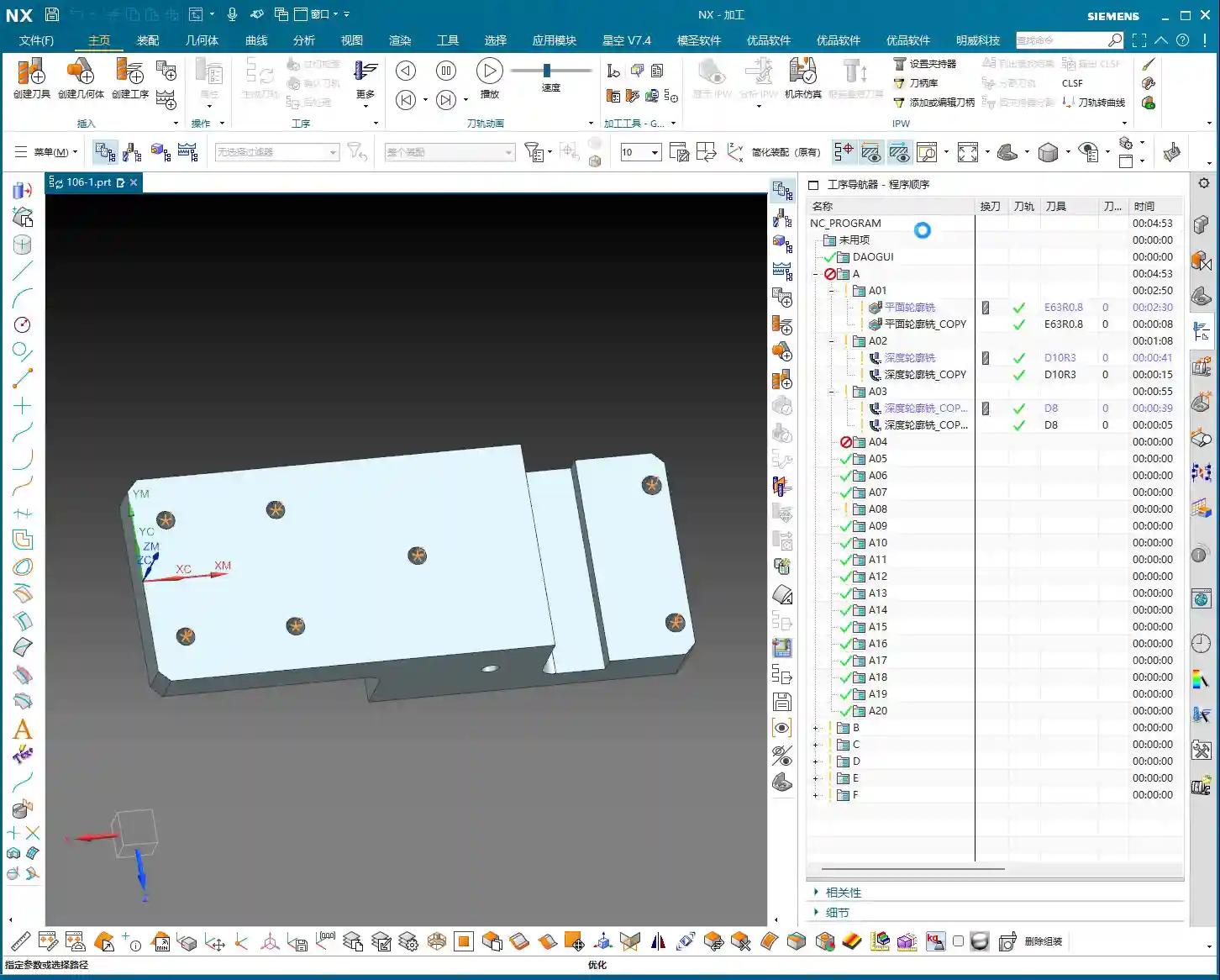
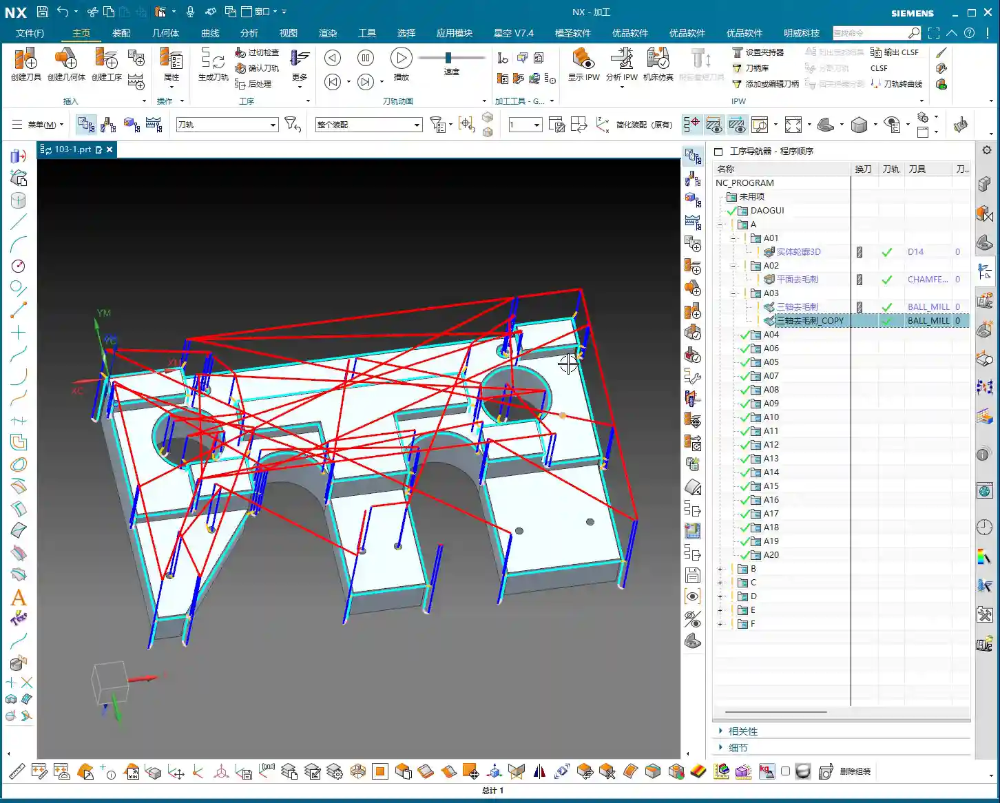
    Leveraging Copy-Paste: Efficiency is King

    In Siemens NX programming, especially for symmetrical or similar machining operations, copy-paste operations are a powerful tool for boosting efficiency. You can directly copy the Face Milling and chamfering operations from Operation A, then simply modify the Work Coordinate System (WCS) and machining region. This significantly reduces repetitive work and ensures operational consistency.

    Programming Tip: After copying an operation, don’t forget to check all parameters, especially clearance planes, lead-in/lead-out strategies, and most importantly, material allowance settings – these are common areas for errors.

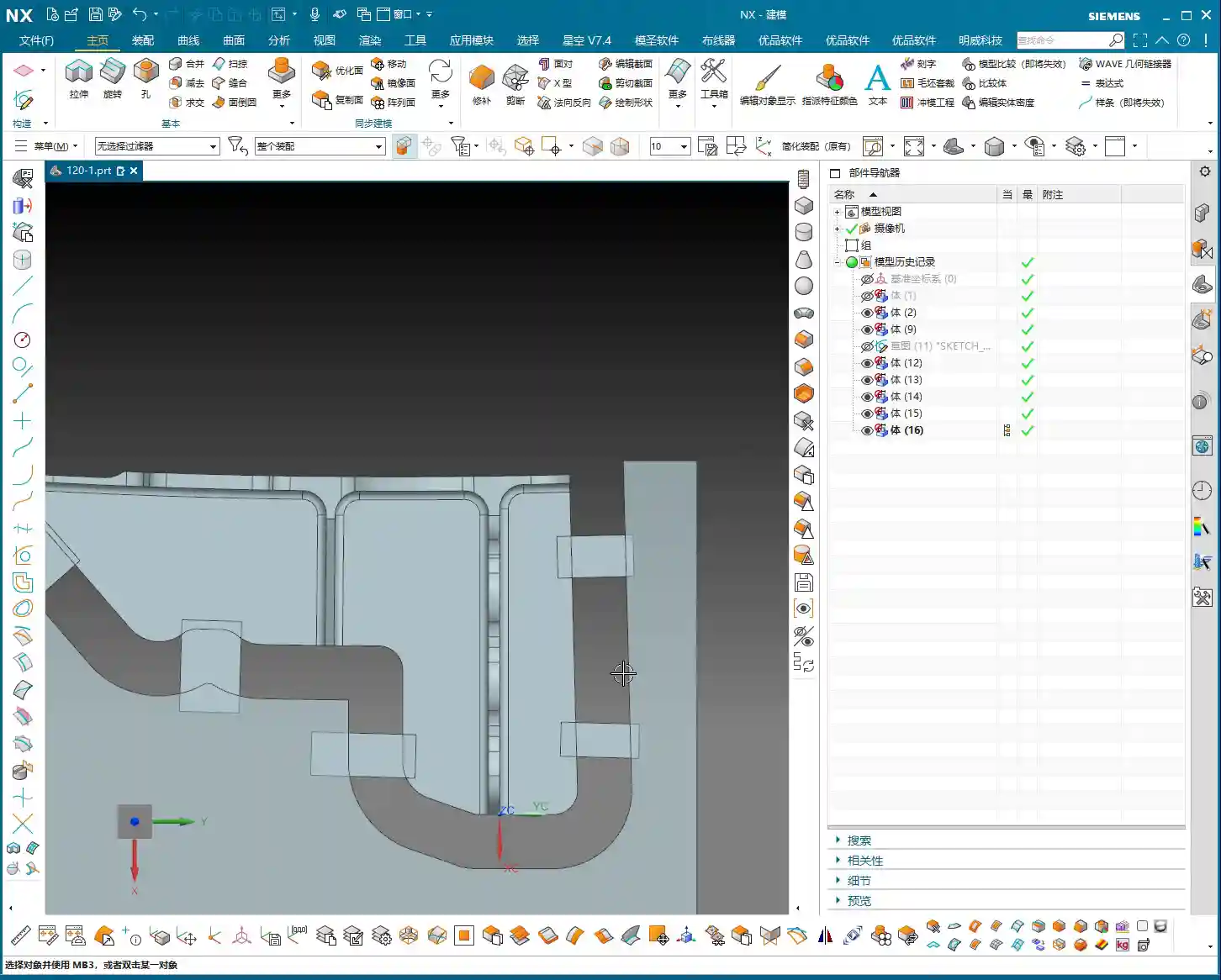
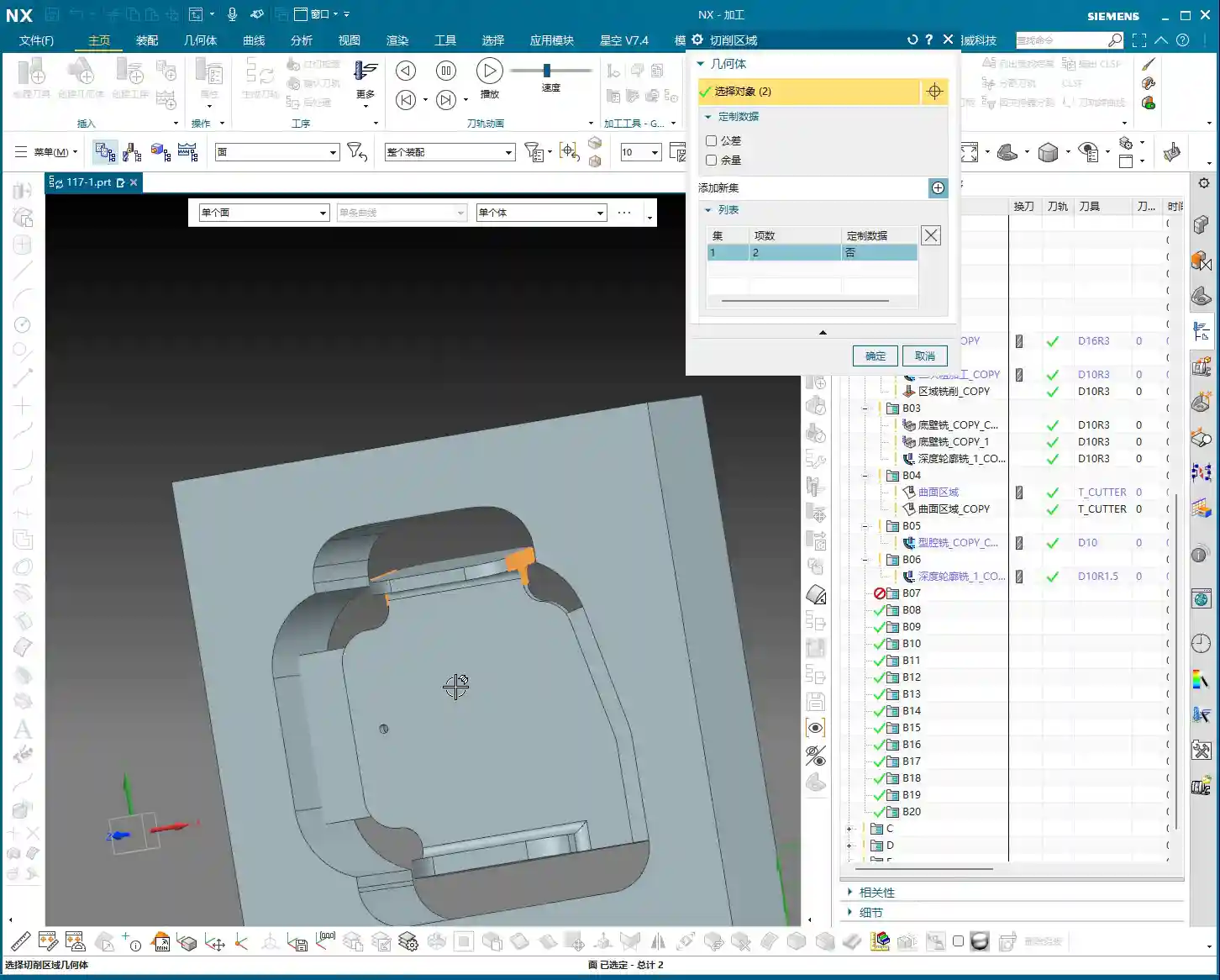
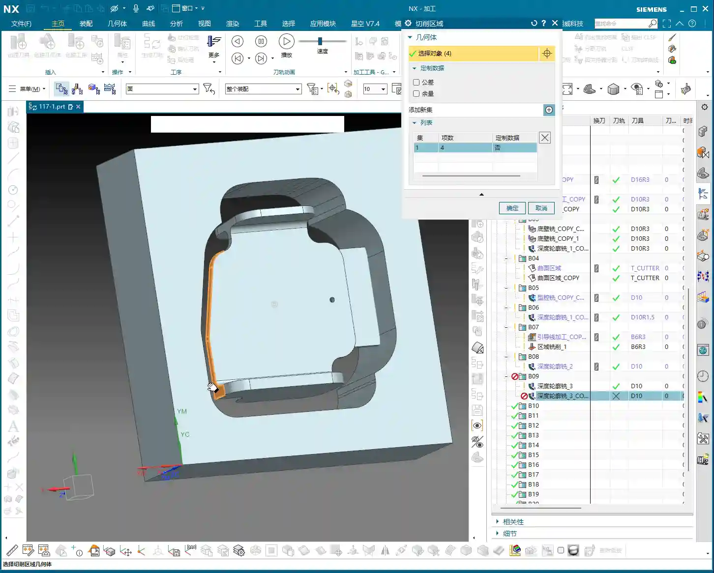
    Step Four: Remaining Feature Machining (Operation C)

    After the first two sides are Roughed, we need to address the part’s holes and Finishing passes. This involves another new Fixturing setup and Work Coordinate System (WCS), typically for machining features on the top or side.

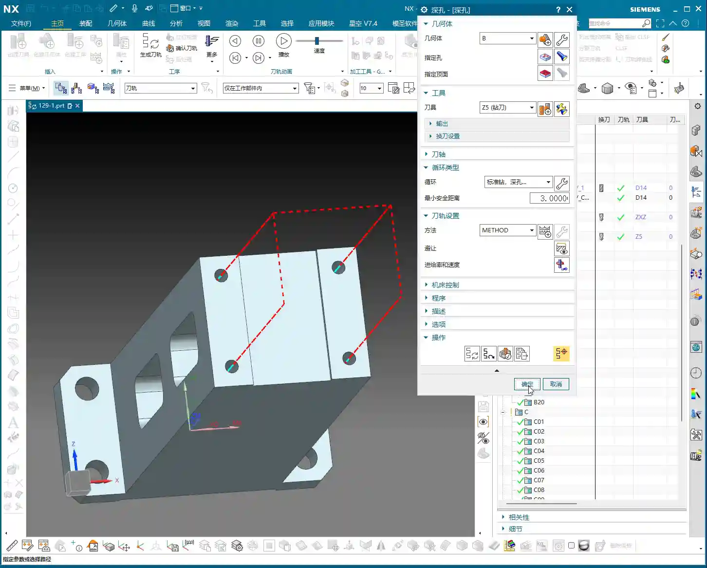
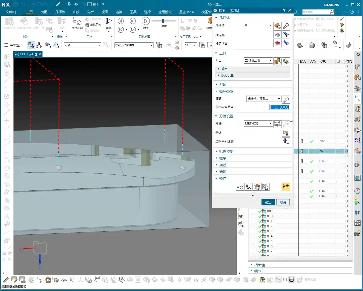
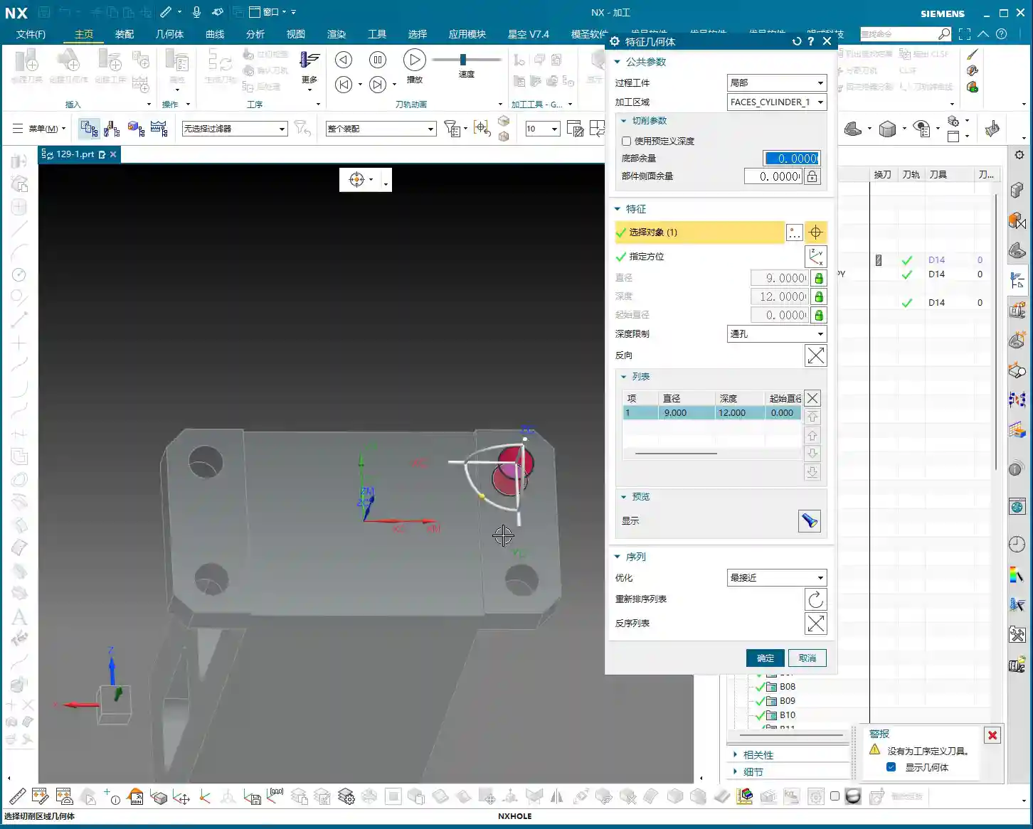
    Hole Machining: Spot Drilling and Deep Hole Drilling

    For hole machining, especially for high-precision holes, it’s not as simple as just plunging a drill bit.

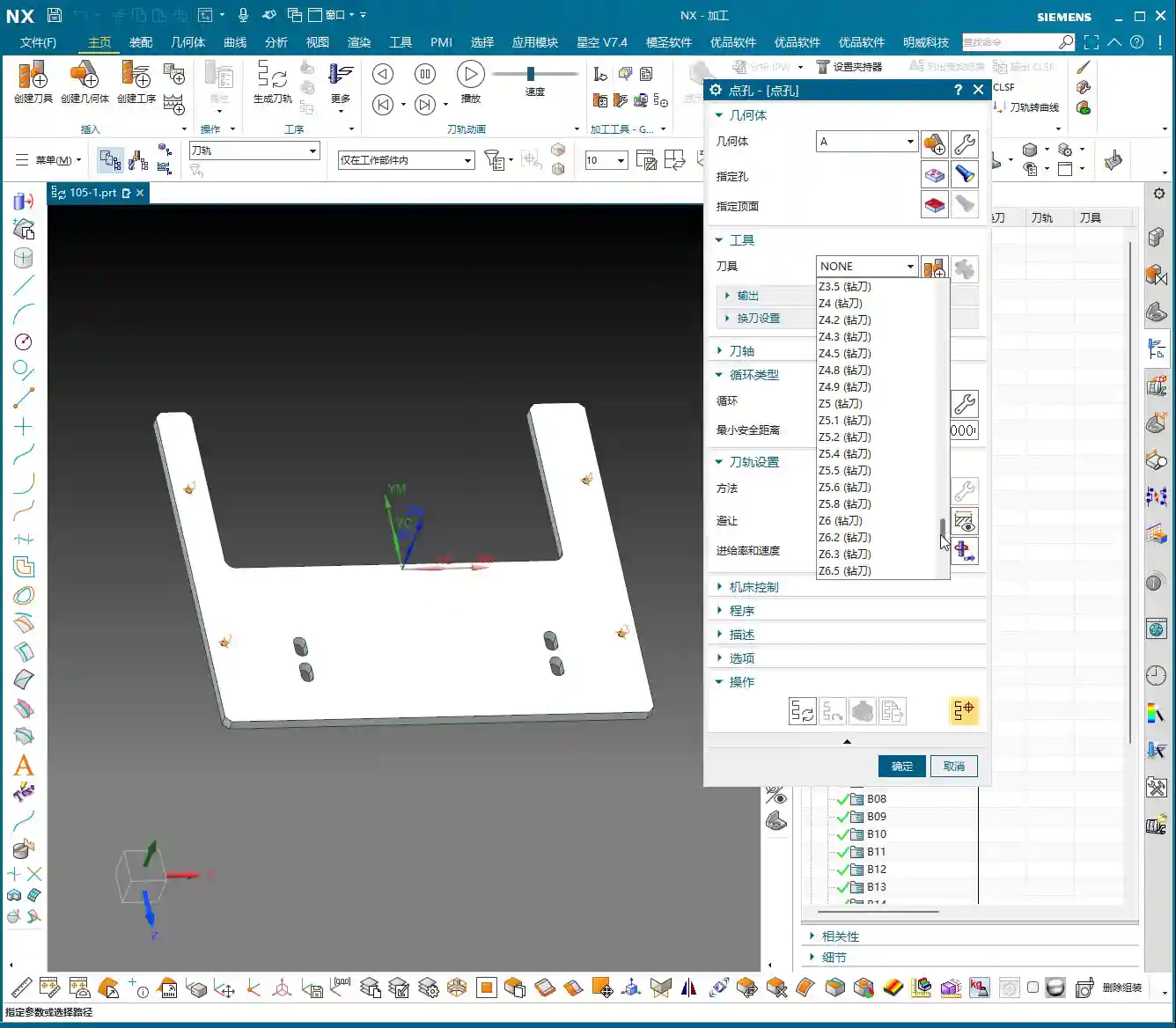
    • Spot Drilling (Center Drilling): First, use a spot drill to establish the center point, preventing the drill from walking. This is fundamental.
    • Deep Hole Drilling: For deep holes, you must use a deep hole drill and set up peck drilling or chip breaking cycles to prevent chip packing and tool burning. Don’t just rely on software simulation; observe the cutting sparks and chip condition – that’s the real feedback.

    For our 5mm diameter hole, we’ll first spot drill for positioning, then use an appropriate drill bit to drill to full depth.

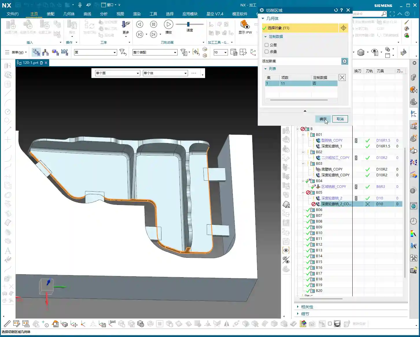
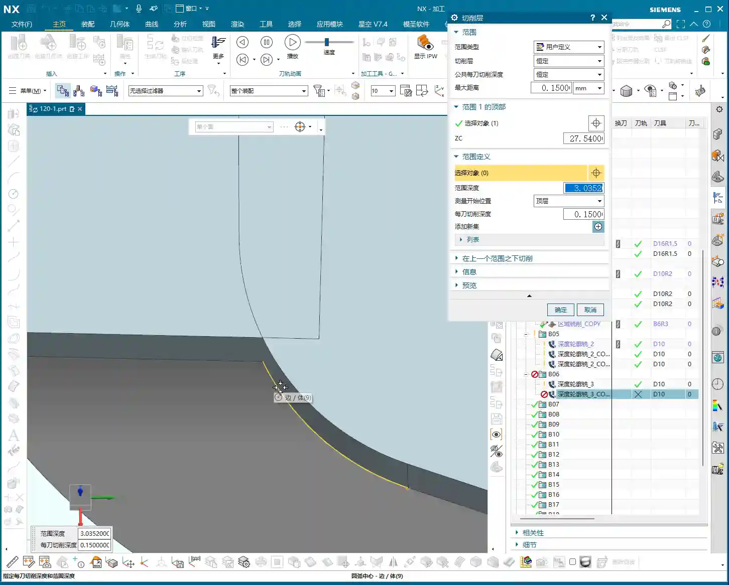
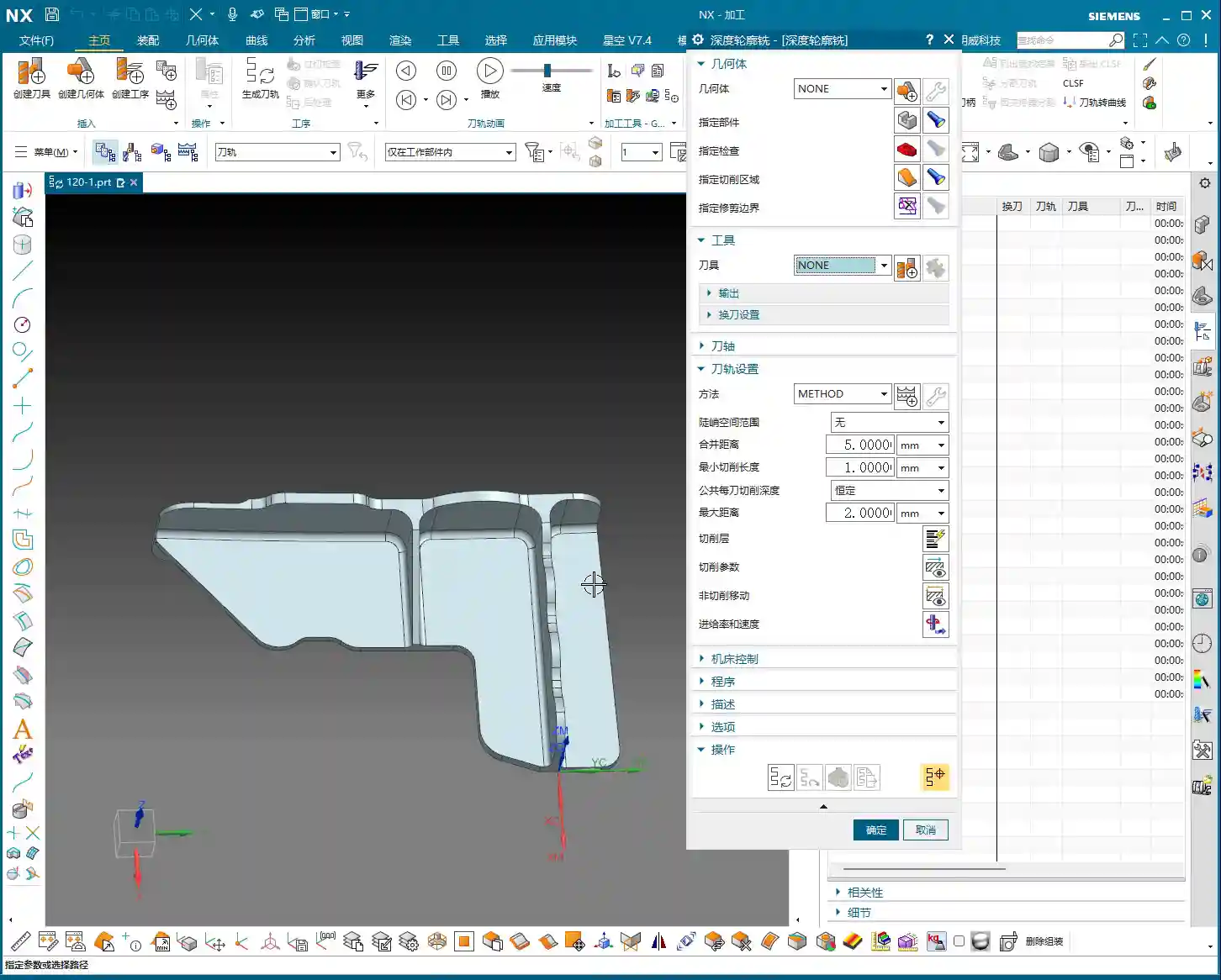
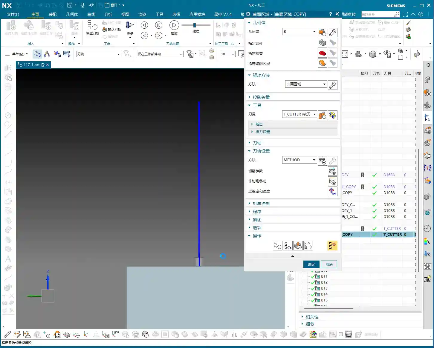
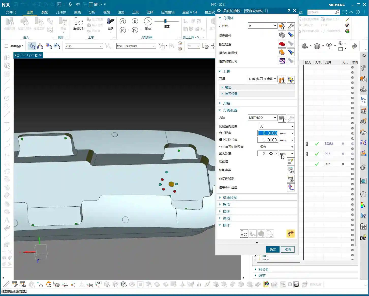
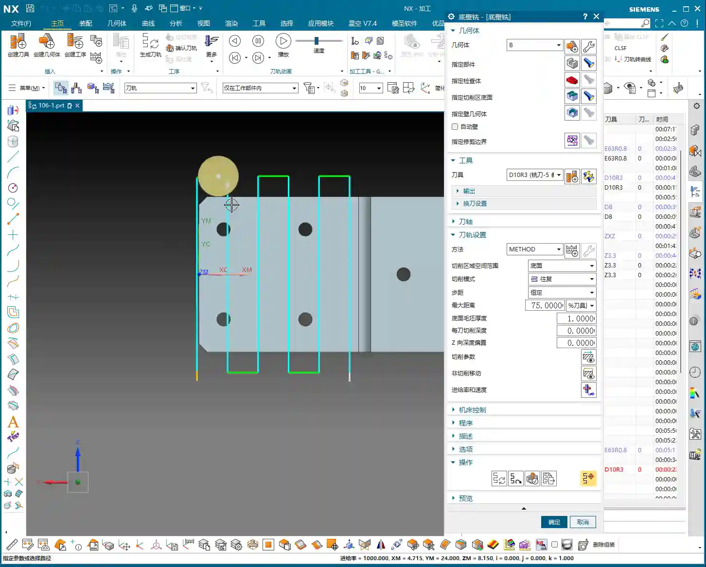
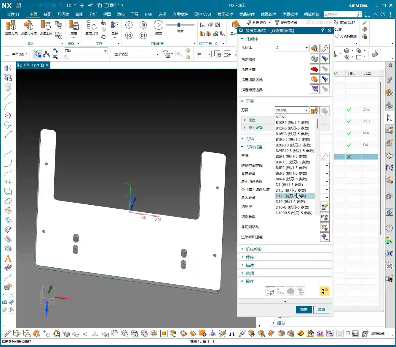
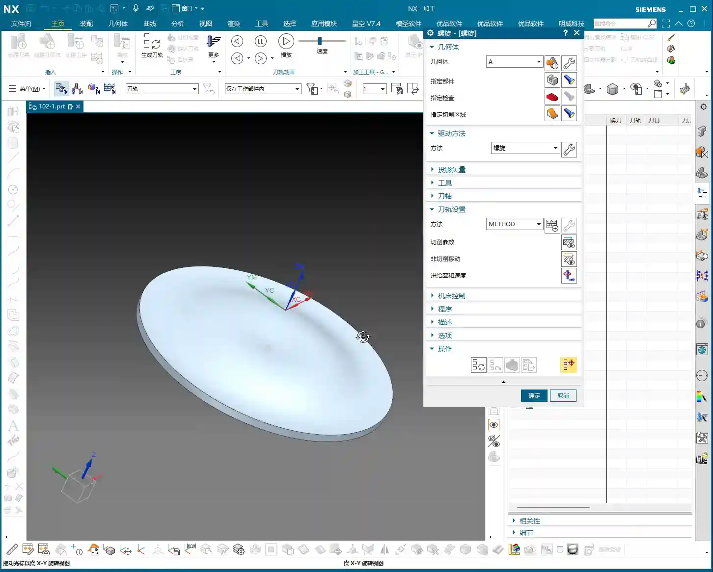
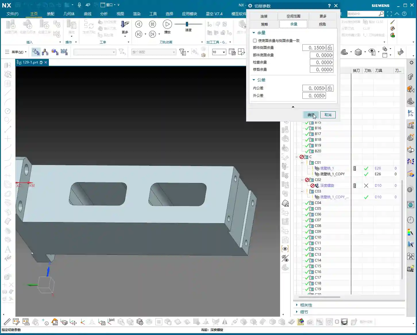
    Pocket Finishing and Helical Milling

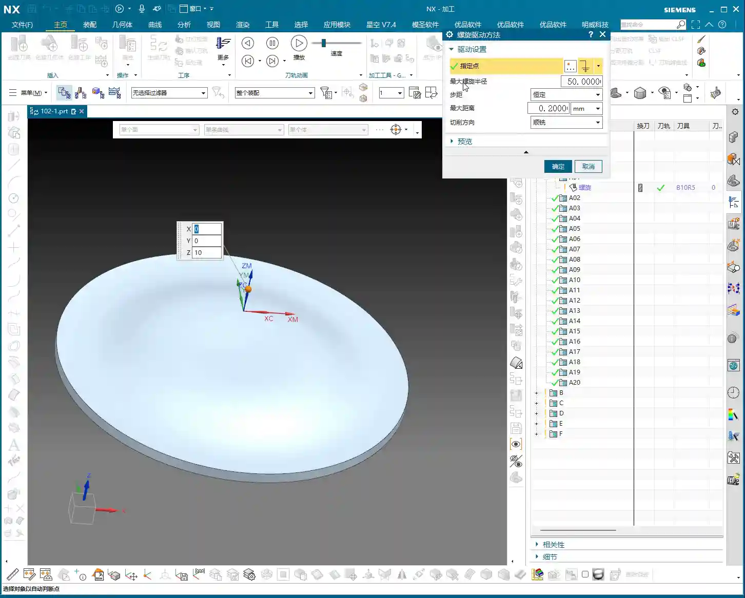
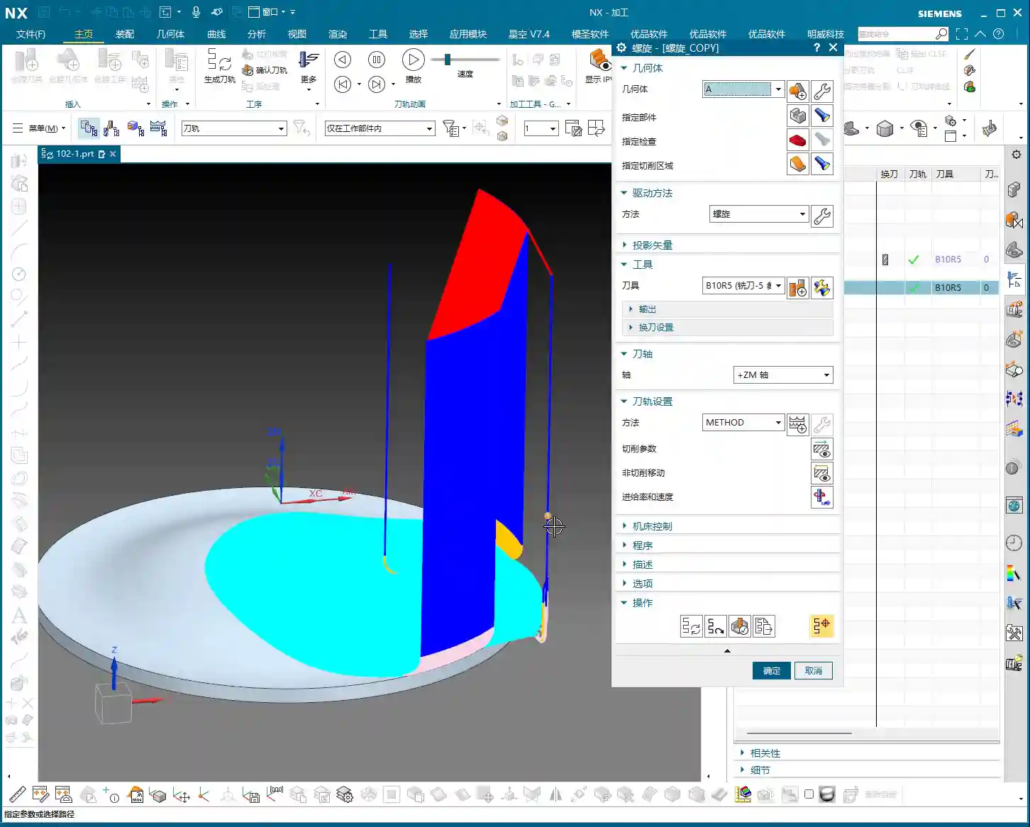
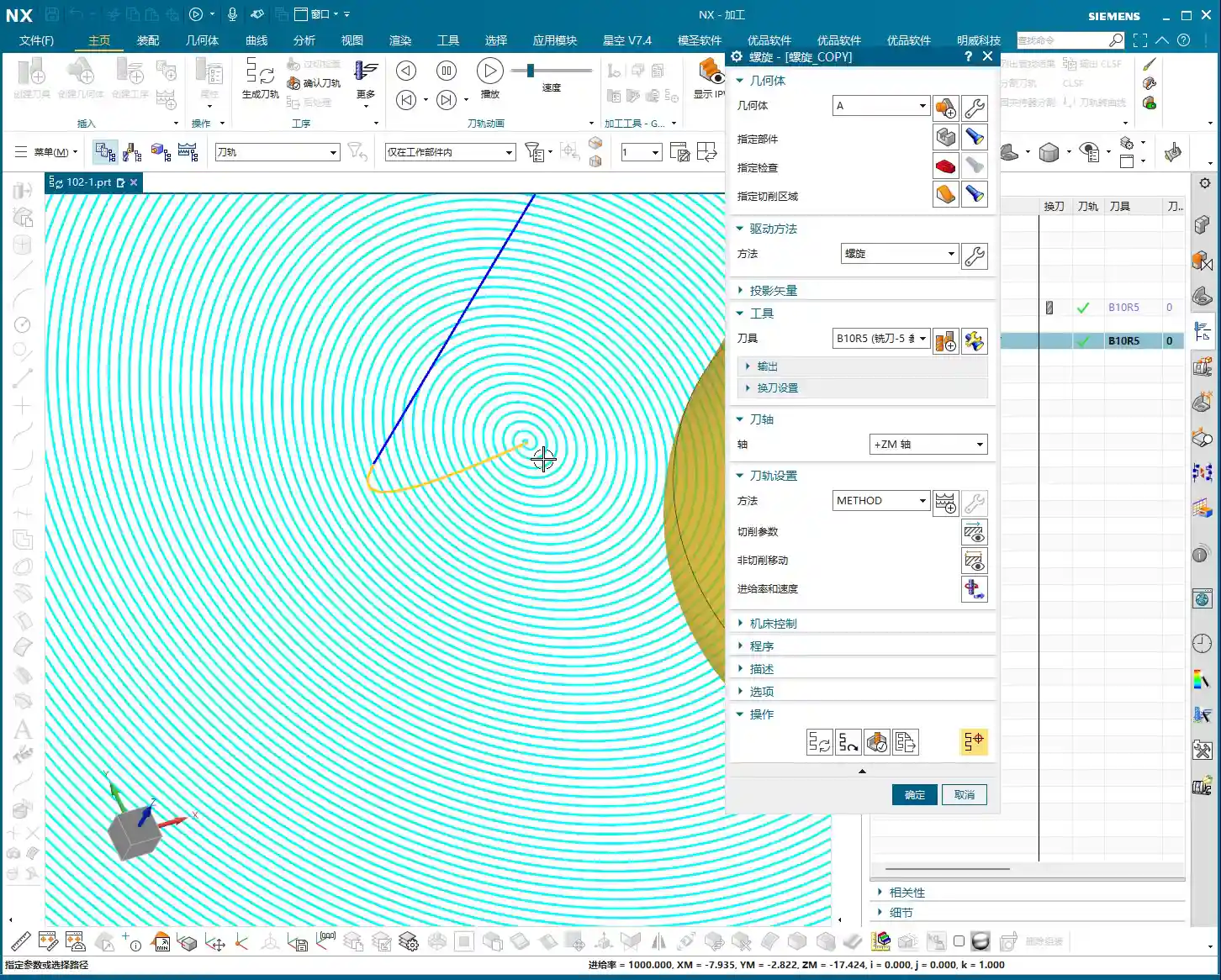
    For pocket Finishing passes, helical milling is an excellent choice. It allows the tool to engage smoothly, avoiding impact, and is particularly well-suited for difficult-to-machine materials like titanium alloys and high-temperature nickel-based alloys. Helical entry allows for precise finishing of the side walls and bottom, step by step.

    Master Wang’s Pro Tip: For Finishing passes, the tool overhang must be short, and rigidity must be excellent. Feed rates and spindle speeds need to be matched, and coolant flow must be ample; otherwise, you’ll easily generate chatter marks, compromising surface quality. For this pocket, we’ll set the bottom stock allowance to 0, leave a 0.05mm allowance on the side walls for the Finishing pass, then use a finishing end mill for a single finish cut to depth.

    Step Five: Program Output and Post-Processing

    Don’t assume everything is done once all the operations are programmed. The most critical step is converting the virtual toolpaths in Siemens NX into the language the machine tool understands – G-code. This requires a setup sheet and post-processing.

    The Value of Setup Sheets and Post-Processing

    A setup sheet is your operational manual, clearly detailing the tooling, parameters, Fixturing, and precautions for each step. It’s the machine operator’s “bible.”

    Post-processing, now that’s a specialized skill. It translates Siemens NX’s internal data into G-code and M-code that specific machine tools (such as FANUC, SIEMENS, etc.) can recognize. For me, Master Wang, modifying post-processors is routine. The goal is to optimize code structure, reduce air cuts, enhance machining efficiency, and even correct some inherent machine tool errors through post-processing (at the ±0.005mm level).

    Marketing Perspective: A clear, accurate, and efficient setup sheet and G-code not only guarantee product quality but also represent the strength of our manufacturing facility. In industrial SEO, this is the best calling card to showcase our “professional, precision, and high efficiency” to clients, helping your product keywords rank high on search engine home pages!

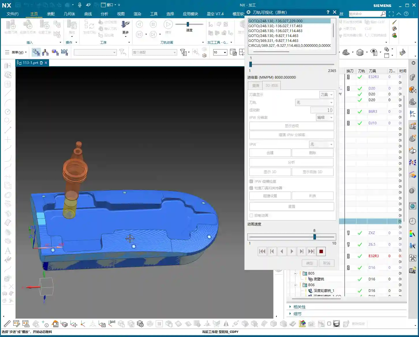
    Toolpath Optimization: More Than Just Software

    Software simulations might show beautiful toolpaths, but real-world machine performance is what truly matters. Too many air cuts? Uneven cutting loads? These issues require careful adjustment within Siemens NX, or optimization at the post-processor level. For instance, using Siemens NX’s “Optimize Toolpath” function can automatically plan the shortest path, reducing non-cutting movements – every second saved is money!

    Summary: Pitfall Avoidance Guide

    Alright, we’ve walked through this multi-operation part programming example from start to finish today. Finally, Master Wang has a few more reminders for you – these are practical experiences you won’t learn from books, so commit them to memory:

    1. Fixturing is fundamental, datums are critical: For multi-operation machining, ensure you select the correct datum surface for each flip and Clamping setup; otherwise, dimensional errors are guaranteed.
    2. WCS management must be rigorous: Clearly define A, B, and C Work Coordinate Systems (WCS) and ensure they correspond precisely in the program to prevent operator confusion.
    3. Tool selection must be appropriate, and cutting parameters must match: Don’t try to use one tool for everything, and never input random parameters. Material, tool, and machine tool – these three must be properly matched.
    4. Separate Roughing and Finishing, leave room for error: Leave sufficient stock for Roughing, then perform the Finishing pass. This is the ironclad rule for ensuring accuracy and surface finish.
    5. Never be careless with post-processing and setup sheets: These are your bridge of communication with the machine tool and the operator. The code must be concise, and instructions detailed; otherwise, they are potential hazards.
    6. Observe cutting sparks, listen to machine sounds: No matter how good the software simulation is, it cannot replace on-site experience. The color of cutting sparks, the shape of chips, and the sound of the machine’s load are all “signal lights” for judging the machining status.

    Remember, programming isn’t “magic”; it’s a combination of science and accumulated experience. Practice more, think more, and summarize more, and you will truly become a master craftsman in machining!

    “`

    👤 About the Author:
    The author is a veteran CNC machining professional with 15 years of industry experience, specializing in UG NX programming. This article is an original work representing personal practical insights.

    ⚠️ Copyright Notice: Unauthorized reproduction or distribution without prior communication is strictly prohibited.

  • Real-world Siemens NX Two-Stage Programming for Webs: Master Wang Helps You Conquer Stock Allowance

    📝 Key Takeaways:

    Mastering Two-Stage Programming for Webs

    Pr…

    [VIDEO_HERE]

    Preface: Why Two-Stage Programming?

    Hello everyone, I’m Master Wang. I’ve been in the machining industry for fifteen years, and I’ve seen it all—turning, milling, planing, grinding, EDM. Siemens NX programming is second nature to me. Today, we’re not going to talk theory; instead, we’ll dive into the web machining of this part and discuss how to master two-stage programming, especially those real-world tricks you won’t learn from textbooks. We’ve already finished machining Side A of the part, so now, let’s flip it over and tackle Side B. Listen closely, because these are genuine, hard-earned insights!

    Side B Work Coordinate System and Stock Definition: Getting Started Right

    First, you need to create the Work Coordinate System for Side B. Select your B-axis for the setup, then specify a plane, for example, by inputting a distance of 100mm, and establish its position. This is the absolute basics; if your Work Coordinate System isn’t set up correctly, your tool will get “lost,” and every path will be wrong.

    Next up is the stock. While I often say that programs can be copied and pasted for convenience and speed, you absolutely must re-verify the stock selection after copying. Especially in multi-sided machining, the stock geometry varies in different orientations. If the stock is selected incorrectly, the program might still generate, but the resulting part will be vastly different from what you intended—a complete waste of effort!

    Roughing Strategy: Digging into Details, Avoiding Pitfalls

    Two-Stage Roughing: The Wisdom of Layered Progression

    For structures like webs that require significant material removal, we typically adopt a two-stage roughing strategy: “first roughing pass” and “second roughing pass.” Simply put, first use a large tool with a significant Depth of Cut (DOC) to remove most of the material (first roughing pass), then switch to a smaller tool, or reduce the Depth of Cut, to more carefully remove the remaining material (second roughing pass), preparing for the subsequent Finishing pass.

    As I always say, “For roughing, first rough it down to the bottom, then follow up with a second roughing pass.” The goal is clear: ensure efficiency while effectively controlling tool wear and preventing excessive cutting loads in a single pass that could lead to chipped or broken tools.

    Stock Allowance Control and Toolpath Depth: Striving for Perfection

    During roughing, many people like to mill a bit deeper, perhaps an extra 1.5mm or 2.2mm, thinking it’s safer. This is a good habit for ensuring complete material removal. However, there’s a “pitfall” you need to watch out for:

    • Master Wang Reveals:“Milling excessively deep is often pointless, because the tool is too large.” Understand? You can set any depth in the software, but in reality, if your tool size is relatively large, or if the part’s geometry is restrictive, the tool simply cannot reach that depth. The extra depth you set won’t be cut, just wasting calculation time. So, don’t just rely on software simulation; look at the cutting sparks!
    • Core Principle: For the first roughing pass, you only need to ensure efficient removal of the bulk material; don’t overthink that extra bit of milling depth. The precise depth control is truly needed during the second roughing pass. At this stage, we’ll consider going “an extra 2.2mm or so,” because the tool is relatively smaller and can reach the desired depth more effectively.
    • Master Wang’s Reminder: Especially in complex structures like webs, which are prone to dead ends, “this area is prone to heavy cutting loads,” so toolpaths must be carefully controlled to avoid overload.

    Residual Stock Removal: Leaving No Dead Ends

    After roughing, there are always some areas where, due to tool size limitations or complex geometry, some “internal residual stock” remains (audio 3:26). If these remnants aren’t thoroughly cleaned up, they’ll cause problems for the subsequent Finishing pass.

    For this residual stock, we typically use specialized toolpath strategies, such as “Deep Profile Milling” or “Hybrid Milling,” using smaller tools for Corner Cleanup or Rest Milling.

    Master Wang’s Experience: This is a crucial detail: “It’s best not to set it to zero stock; if you do, toolpaths will also appear on the exterior.” What does this mean? It means that at the edges of the roughing pass, do not set the stock allowance to 0mm. Even leaving a 0.05mm stock allowance can significantly reduce the risk of the tool scratching the workpiece edges, preventing burrs. This is a practical trick you won’t learn from textbooks, and it can save you a lot of rework time and money!

    Of course, for external contours that do not connect to subsequent finishing surfaces, you can choose to leave no stock allowance and mill directly to size; that’s perfectly fine.

    Finishing Process: The Secrets of Surface Finish

    Tool Selection and Feed Strategy: Pursuing Perfection

    Finishing pass, as the name suggests, aims for optimal surface finish and dimensional accuracy. Therefore, we typically select tools with smaller radii, such as the R1.5 or R2 ball nose or bull nose end mills that I frequently use.

    For toolpath strategy, the Finishing pass often opts to “feed in from the outside, milling inwards for the finish cut.” This avoids the impact and tool marks that can occur when a tool directly plunges into the interior of the workpiece, ensuring consistent surface quality.

    Master Wang’s Tip: During the Finishing pass, the stock allowance for most curved surfaces or side walls will be set to 0mm to ensure final dimensions. However, for transition areas connecting the bottom and side walls, a small amount of stock allowance (e.g., 0.1mm) is sometimes left for better blending and to avoid overcutting, then smoothed out with strategies like “Hybrid Milling.”

    Avoiding Finishing Pitfalls: The Double Toolpath Issue

    When programming Finishing passes, you might sometimes notice “two layers of toolpaths” in the software simulation (audio 9:28), even though you only intended for one. This is a common “illusion” and “pitfall” that many people encounter.

    Master Wang’s Analysis: Double toolpaths usually occur due to improper datum height or thickness parameter settings. The software interprets a certain height as a datum, then generates an additional layer based on your parameters. This is extremely dangerous in actual machining and can lead to overcutting, air cutting, or even scrapping the part directly!

    Solution: When this happens, we must immediately check and adjust the thickness parameter. For example, change the thickness from its default value to a smaller number, such as 0.1mm. As long as this thickness setting is reasonable and distinct from the actual part height, the extra toolpaths will immediately disappear, leaving only the single layer you intended.

    Master Wang Emphasizes: “If their heights are different, just reduce it a bit”—this principle applies to many similar scenarios. The core idea is to tell the software what your true machining depth or boundary is.

    Program Reuse and Optimization: Efficiency Above All

    Copying and Modifying: The Siemens NX Programming Shortcut

    In practical work, if a part has many similar features, or like our example today, a single part has multiple machining faces, copying existing programs is the most direct way to boost programming efficiency.

    Master Wang’s Experience: Copying and pasting is great, but never get lazy. After each copy, you must carefully inspect and modify several core parameters:

    • Stock Definition: Ensure it corresponds to the current machining state.
    • Machining Face Selection: Re-select the correct machining area.
    • Toolpath Depth and Stock Allowance: Adjust according to the roughing and finishing stages and specific requirements.
    • Boundary Type: For example, whether to feed in from the outside or inside, and if extension is needed.

    Master Wang’s Maxim: “If programs are highly similar, feel free to copy them, but the devil is in the details!” Oversights in minor details are often what lead to rework or even scrapped parts.

    Considerations for Machining Sequence: Rough First, Then Finish; Bottom First, Then Sides

    A logical machining sequence can significantly improve efficiency and quality. The fundamental principle is to rough first, then finish. However, within the Finishing pass itself, there’s another subtle point.

    Master Wang Suggests: “You should finish the bottom first, then the side walls.” Why? Because machining the bottom first ensures its flatness, providing a stable datum for the subsequent Finishing pass of the side walls. If you machine the side walls first and then the bottom, vibrations or chips generated during the bottom cutting might scratch the already finished side walls, affecting the surface finish. These are all lessons learned the hard way!

    Master Wang’s SEO and Promotion Secrets

    In this digital age, simply being able to craft high-precision parts by hand isn’t enough. You also need to ensure your products, your technology, can be seen by customers amidst the vast network. If you can both manually machine high-precision parts and ensure your product keywords consistently rank on the first page of search engines, that’s true skill!

    So, Master Wang is not just a veteran on the shop floor, but also an expert in online promotion. When writing these technical tutorials, I deliberately integrate common industry technical terms and pain points, such as “Siemens NX programming,” “web machining,” “stock allowance control,” “machining pitfalls,” and so on. This is what we call SEO (Search Engine Optimization).

    Remember, no matter how good your technology is, it’s useless if no one knows about it. Learning to disseminate your professional knowledge in a way customers can understand and find is as important as achieving a machining accuracy of ±0.005mm on the machine!

    Summary: A Pitfall Guide

    Finally, Master Wang has summarized a few points for you; these are common mistakes in real-world machining. Avoid them, and you’ll save yourself a lot of trouble:

    1. Don’t blindly trust software simulations: It’s just a tool; the final result depends on the actual tool, material, and machine conditions.
    2. Leave stock allowance on roughing boundaries: Even 0.05mm can effectively prevent the tool from scratching the workpiece edges and avoid burrs.
    3. Beware of double toolpaths during finishing: Carefully check height and thickness parameters, adjusting as necessary to ensure only one effective toolpath.
    4. Plan your machining sequence logically: Especially for Finishing passes, “bottom first, then sides” can improve quality and efficiency.
    5. Be meticulous with program reuse: After copying and pasting, key parameters such as stock, machining faces, depth, stock allowance, and boundaries must be checked one by one.
    6. Avoid frequent tool changes: Unless strictly required by the process, try to complete similar operations with the same tool to reduce tool change time.
    7. Setting “zero stock” is a pitfall; avoid it unless absolutely necessary: Especially in edges and transition areas, it’s better to leave a tiny bit of stock allowance than to overcut or scratch the part.

    Alright, that concludes today’s lesson. Go back, reflect on it, get hands-on, and ask me if you have any questions!

    👤 About the Author:
    The author is a veteran CNC machining professional with 15 years of industry experience, specializing in UG NX programming. This article is an original work representing personal practical insights.

    ⚠️ Copyright Notice: Unauthorized reproduction or distribution without prior communication is strictly prohibited.

  • Siemens NX Programming Best Practices: Master Wang’s Secrets for Building Connection Ribs on Complex

    📝 Key Takeaways:

    Siemens NX Programming Best Practices: Connection Ribs

    Hello everyone, I’m Old Wang, Master Wang. I’ve been in the machining industry for…

    [VIDEO_HERE]

    Hello everyone, I’m Old Wang, Master Wang. I’ve been in the machining industry for fifteen years, from the shop floor covered in swarf to sitting in front of the Siemens NX interface – I’ve seen it all. Today, let’s skip the theory and talk about the hard-earned, practical machining skills you won’t find in textbooks. Specifically, we’ll discuss creating manufacturing connection ribs for complex parts and how to program tool paths effectively to ensure your parts are produced quickly and accurately, while avoiding critical deformation.

    Don’t just stare at all the fancy commands in Siemens NX. Remember, software is merely a tool; the core lies in your understanding of the part, the material, and the machine. Listen up: do this job right, and it’s craftsmanship; mess it up, and you’re just making scrap!

    Step One: Part Geometry Analysis – Know Your Part, Know Your Process

    When you get a part, don’t rush into modeling and programming. First, look, and look carefully! That’s the first rule from us old masters. Only by understanding your part inside and out can you master the machining process.

    Identifying Surfaces and Planar Faces: Avoiding Pitfalls

    I always tell my apprentices: when you get a drawing or import a model, the first thing you do is use Siemens NX’s analysis tools to thoroughly understand the part’s geometric features. Don’t just glance at it; examine every single face clearly:

    • Which are planar faces? Planar face machining is simpler and more efficient, but you still need to pay attention to dimensional accuracy and surface roughness.
    • Which are curved surfaces? Especially freeform surfaces—this is where your Siemens NX expertise is truly tested. Curved surface machining involves complex tool paths and is prone to high cutting forces, so you need to pay extra attention to tool selection and feed strategies. Just now, when I analyzed that part, I found one area that wasn’t purely flat; it was a curved surface. That immediately raised a red flag. A standard flat-end mill definitely won’t work there; you’ll either need to finish it with a ball end mill or figure out another way to avoid it.

    Only by understanding these thoroughly will you know where the machining challenges lie and where problems are likely to occur. It’s like going into battle: you need to know where the enemy’s strongpoints are, not just blindly charge in.

    Considering Radii and Slopes: Key Factors for Tool Selection

    Small radii and slopes are critical information that determines which tool you use and how you machine.

    • I just measured, and the part has many radii: R4, R2, and even R5.5. This tells us that we might use a larger tool for roughing, but for finishing side walls and Corner Cleanup, we’ll need to switch to smaller tools. For example, for an R4 fillet, you’ll need at least an R2 ball end mill or flat-end mill for Corner Cleanup; otherwise, you won’t clear the corner properly, and all your effort will be wasted.
    • Next, consider the slopes. Some faces look flat but actually have a slight incline – that’s a slope. If the slope changes significantly and you use a flat-end mill, obvious step marks will appear, resulting in poor surface quality. In such cases, you need to consider using a ball end mill or bull nose end mill, or even engaging 5-axis simultaneous machining, to ensure a smooth finish.

    All of this can be identified using Siemens NX’s “Analysis Tools.” Don’t be lazy; a few extra clicks of the mouse now will save you a lot of hassle compared to re-working a part after machine issues arise. That’s real money down the drain!

    Step Two: Constructing Manufacturing Connection Ribs – Virtual Support, Real Stability

    Some parts are thin, weak, and complex, especially thin-walled components for aerospace applications, which are highly susceptible to deformation and chatter during machining. This is where manufacturing connection ribs come in extremely handy. They are not part of the final component but serve as temporary support during the machining process, and are cut off once machining is complete.

    “Enveloping Body” and Stock Allowance Setting: Ample Material, Sufficient Clearance

    First, in Siemens NX, we need to create an “enveloping body” for the part, which is essentially our raw material blank or machining boundary. This enveloping body must not only enclose the part itself but also provide sufficient space for our connection ribs. I typically offset additional allowance (extra material) on all sides (top, bottom, left, right) of the enveloping body. For instance, I might start with 20mm and then adjust it to 15mm or even 14mm based on actual requirements. This allowance is crucial; it directly impacts the thickness of your connection ribs and the clearance needed when you eventually cut them off. You can’t make the ribs too thin, or they won’t provide adequate support, nor too thick, as that makes cutting them off a hassle.

    Furthermore, if you want to leave some allowance when machining the connection ribs, for example, using a Ø25 tool for cutting them off, then our enveloping body at the connection rib locations must extend an additional 12.5mm (tool radius) outwards. This ensures there’s enough material to cut.

    Extruding and Adjusting Critical Faces: Meticulous Geometric Refinement

    Building connection ribs isn’t just about drawing a few lines. We need to precisely extrude and adjust the relevant faces of the part to provide a stable “foundation” for the connection ribs. For instance, I just noticed some faces were excessive or had small corners. To ensure the connection ribs connect and support better, I need to use the “Extrude” command to extrude these faces outwards by -1mm, or use “Replace Face” to replace irregular areas, thereby ensuring the integrity and smoothness of the geometric structure. This process is like sculpting, meticulously refining bit by bit. There can be no burrs or breaks, otherwise, the resulting connection ribs will be like a shoddy construction.

    Sketching and Extruding Connection Ribs: The “Lifeline” for Stable Machining

    Next comes the main event: drawing the connection ribs. This requires a strategic approach:

    • Placement: Connection ribs should be positioned at the part’s weakest points, where deformation is most likely, and at load-bearing areas. Generally, this means along the edges and thin-walled regions of the part.
    • Quantity and Density: Determine this based on the part’s rigidity and the magnitude of machining forces. Too few ribs won’t provide enough support; too many will increase subsequent cutting time and cost. You need to find a balance.
    • Sketching: Draw the connection rib sketches on the relevant faces of the part. Lines, arcs, or splines are all acceptable, but they should be as simple as possible to facilitate subsequent machining and cutting off. Just now, I sketched a few auxiliary lines and then used the “Extrude” command directly to extrude these sketches into solid bodies. I usually set the thickness to 5mm initially, which can be adjusted later.

    These connection ribs are the “lifeline” for the part during machining on the machine tool. They determine whether your part is machined stably and successfully, or ends up as scrap mid-process.

    “Replace Face” for Uniform Height: Ensuring Support Stability

    This is a highly practical “pitfall avoidance” technique! Because various faces on the main part might have different heights, if you simply extrude the connection ribs, they might not end up on the same plane, leading to unstable support or even gaps. I just noticed that many connection ribs had varying heights. In such cases, you need to use the “Replace Face” command to uniformly replace the top faces of all connection ribs to a single reference plane on the part (e.g., the highest point or a datum plane). This ensures that the tops of all connection ribs are at the same height, guaranteeing overall support stability and facilitating subsequent clamping with straps, thereby reducing chatter. Don’t underestimate this step; it’s critical for ensuring your part remains absolutely stable during machining!

    Step Three: Tool Selection and Tool Path Optimization – The Art of Balancing Efficiency and Precision

    Once the connection ribs are built and the raw material blank is defined, it’s time for programming. This is my forte, and with Siemens NX, it’s all about “finesse.”

    Deriving Tools from Radii: The Right Tool for Maximum Effectiveness

    Selecting the wrong tool is simply burning money. The radii we just analyzed now come into play. Determine the tool type and size based on the smallest radius and machining requirements.

    • For example, for side wall Corner Cleanup with a minimum radius of R2, you’ll need at least a Ø4 flat-end mill or an R2 ball nose end mill. I just decided to use a Ø10 or Ø12 flat-end mill to machine the side walls.
    • For the final cutting off of connection ribs, to ensure efficiency and surface quality, a slightly larger tool is typically used. I selected a Ø24 or Ø25 flat-end mill, leaving 12mm or 12.5mm of cutting allowance. The principle for tool selection is: while meeting dimensional and surface finish requirements, opt for the largest possible tool to reduce tool deflection and increase machining efficiency.

    Don’t just rely on software recommendations; you must make comprehensive judgments based on your machine rigidity, material hardness, and tool material. Otherwise, you’ll break tools and scrap parts, and it’ll be too late for regrets.

    Optimizing Cutting Layers and “Air Cuts”: Ensuring Every Cut is Productive

    This is paramount for efficiency! Tool paths automatically generated by Siemens NX often contain numerous redundant cutting layers and air cuts.

    • Managing Cutting Layers: I just did this – deleted all the default cutting layers generated by the system, keeping only the most effective ones, or manually adjusting them based on actual conditions. Don’t foolishly let the software calculate every single layer; many are just idle moves, wasting time, wearing out the spindle, and increasing program size. Only keeping layers with actual material removal is the optimal approach.
    • Reducing Air Cuts: When the tool moves in the air without cutting, that’s an “air cut.” More air cuts mean longer machining times. In Siemens NX, you can minimize air cuts by adjusting parameters such as lead-in/lead-out, connection methods, and non-cutting move strategies. Especially for complex surfaces and cavity machining, optimizing air cuts can save a significant amount of time. The version of Siemens NX I’m currently using, with high-efficiency tool paths like Adaptive Milling, can greatly reduce air cuts and ensure more stable cutting.

    Remember, time is money, especially in mass production. Every minute saved directly contributes to increased profit. This is a key “selling point” we can emphasize when promoting industrial products online: high-efficiency, low-cost precision machining – that’s what customers love to hear!

    Siemens NX Programming Best Practices: The Clever Use of Post Processors and Macros

    Siemens NX programming isn’t just about clicking a mouse. Advanced users also need to be proficient with Post Processors and Macros.

    • Post Processor Modification: Your machine tool might have specific commands or cycles. In such cases, you’ll need to modify the Post Processor so that the G-code generated by Siemens NX can perfectly adapt to your machine. This requires some understanding of machine parameters and control system codes like Fanuc and Siemens. Don’t be intimidated; master this, and your Siemens NX programs will run flawlessly on any machine. I even fine-tune Post Processors based on different machine characteristics to output more efficient G-code, reducing unnecessary tool changes or retract moves.
    • Utilizing Macros: For highly repetitive operations, such as standard drilling cycles or engraving, you can write macros to complete them with a single click, significantly boosting efficiency. It’s like installing an “accelerator” for Siemens NX, turning your experience into reusable code.

    When you master all of these, you won’t just be a Siemens NX operator; you’ll be a true Siemens NX expert, an “old master” of the industrial world. The reason our high-precision parts are promoted so successfully online, with keywords (such as “high-precision 5-axis machining” or “custom complex structural components“) consistently ranking on the front page, is precisely due to this solid process foundation and efficient programming capability, which ensures product quality and on-time delivery. Customers look for tangible benefits, not flashy advertising.

    Summary: Pitfall Avoidance Guide

    Alright, everything I’ve discussed today has been learned through hard-won lessons. Finally, let me summarize a few key points for you. Remember, these are Master Wang’s Ironclad Rules for avoiding pitfalls:

    • Never skip geometric analysis! Especially for curved surfaces, radii, and slopes – these are the soul of tool selection and tool path strategy. Don’t rush into it; first, think the job through carefully in your head.
    • Connection ribs are not to be sketched haphazardly! You must ensure their structural rigidity, proper placement, and uniform height (frequently use “Replace Face”). Otherwise, if chatter or deformation occurs during machining, your part will be scrapped.
    • Tool selection should be “clever,” not just “expensive”! Size, type, and material must be determined based on part characteristics and machine performance. Choose the wrong tool, and you’ll either break the tool or chip its cutting edge.
    • Tool path optimization saves money! Especially with cutting layers and air cuts – reduce them whenever possible. Don’t let your machine run idle; that’s literally burning your money.
    • Don’t just rely on software simulation; observe the cutting sparks! No matter how perfect the software simulation, it cannot replace the experience of actual machine operation. Cutting sounds, spark color, and chip evacuation conditions can all tell you if there’s a problem with the machining process.
    • Pay close attention to clamping and heat treatment! Even the best programming is useless without secure clamping and appropriate post-processing (e.g., heat treatment to prevent deformation). Every link in the entire machining chain must be robust.

    Alright, that’s it for today’s lesson. Practice more, think more, and summarize more, and you too can become the “Master Wang” of your shop floor!

    👤 About the Author:
    The author is a veteran CNC machining professional with 15 years of industry experience, specializing in UG NX programming. This article is an original work representing personal practical insights.

    ⚠️ Copyright Notice: Unauthorized reproduction or distribution without prior communication is strictly prohibited.

  • Siemens NX Programming in Practice: Detailed 2nd Operation for Efficient Rib Machining – Master Wang

    📝 Key Takeaways:

    Practical Rib Machining (2nd Operation): Master Wang’s Guide to Siemens NX Programming & Optimization

    First Step: Workpiece Coordinate System (WCS) B-Side Adjustment and Datum Definition

    Hello everyone, this is Master Wang. In the last lesson, we discussed machining the front side of the connecting ribs. Today, we’ll continue and tackle the back side of this part, which is the second operation (Op 2). Listen up, this area isn’t simpler than the front; there are plenty of crucial details.

    For the back side machining, the first step is to modify the Work Coordinate System. Simply change the primary Machine Coordinate System (MCS). To put it simply, select the B-side. Double-click the WCS and adjust the Z-axis direction to ensure it points towards the back side we intend to machine. Sometimes, when I’m too quick, I might place the origin in the middle, but that’s a no-go. This job demands high precision, so the origin must be placed at the designated location, like our datum corner, not just anywhere. One slip-up, and the tool will cut into the part.

    Remember, whether it’s the A-side or B-side, as long as the Z-axis direction is correct, the program won’t show errors (turn red); this is fundamental Siemens NX logic. But don’t even think about double-clicking and directly modifying an A-side program to run on the B-side; that program will definitely error out and turn red! That operation is absolutely incorrect. As long as we ensure the J-axis points upwards, milling can commence from either side.

    We also need to thoroughly check the datum points for the B-side, ensuring they correspond with the A-side datum points, both being at the same location. If the front’s datum is zero, then conversely, the back’s datum should also be zero. These finer points aren’t necessarily taught in textbooks.

    Roughing Strategy: Rib Side Roughing and Stock Allowance

    Rib Side Roughing Toolpath Optimization

    Next is the **roughing** of the rib’s side. We need to **rough** out this area. Here’s a critical consideration: Is it better to **rough** everything out, or to **rough** to a certain face first, and then perform a **finishing pass**?

    In my experience, for connecting ribs like these, especially if they are connected on both sides, we can start by only **roughing** down to this specific face. Once this area is **roughed** out, meaning the initial **Rest Milling** is complete, we then proceed with a Finishing pass. After the **finishing pass**, we perform another **roughing** operation, either a secondary **roughing** or semi-**finishing** mill. This staged approach can effectively reduce machining stress, which is paramount for preventing deformation, especially with materials like titanium alloys and high-temperature nickel-based alloys.

    Therefore, we’ll first **rough** this face. Select the final face to ensure our **roughing** range is correct. Then, change the program mode from automatic to manual face selection. This allows for precise control of the machining area, preventing air cutting or milling into unintended regions.

    Program Duplication and Parameter Adjustment Pitfalls

    The programming method for the other side (front) is essentially the same as for this (back) side, so we can directly duplicate the previous roughing program. After duplicating, remember to change the WCS to the B-side, and then use Teach Geometry to control the toolpath. This will save a significant amount of time.

    Oh, right, I think I selected the wrong tool earlier when programming the other side. You might have noticed. My apologies, I was a bit too quick! Let’s re-select; we should be using an R10 or R12.5 tool (the audio mentioned 12R3, then 10, then 12; I understand this as various options, ultimately choosing the most suitable). That’s how it is when you’re working—if you make a mistake, you fix it; don’t just power through it!

    Once we finish programming, we *must* check everything: ensure all programs are set for either the A-side or B-side, and that the tools are correct. If everything checks out, then click generate. I sometimes get too quick and make selection errors. Such minor mistakes are common in production, but a single oversight can scrap a part worth hundreds of thousands (of RMB), so even the most seasoned machinist needs to be meticulous.

    Duplicate all these **roughing** programs, then sequentially modify the WCS to the B-side and select the corresponding machining faces. Remember to adjust the spindle speed and feed rate (F-value and S-value) according to the material and tool conditions. For example, here, I’m setting the spindle speed to 1000 RPM and the feed rate to 100 mm/min (approx. 3.9 inches/min), but these are for reference only. Actual values must be determined based on the tool manufacturer’s parameters and machine performance. Don’t just rely on software simulations; observe the cutting sparks, listen to the cutting sound, and feel the chip temperature!

    Detailing: Finishing Pass for Deep Pockets and Connecting Features

    Corner Radius Area Treatment: The Clever Use of Offset Surfaces

    Now, let’s look at the corner radius areas of the connecting ribs. This spot is a bit complex, with many fillets. We generally avoid machining directly on these fillet regions. My approach is to first create an Offset Surface here. Essentially, we’re making a sheet body.

    Why not just delete the fillet faces directly? Because direct deletion might lead to inaccurate recognition of other machining faces later on, or result in broken surfaces. Creating an **Offset Surface**, however, provides a smoother, more controllable guide surface for the toolpath without altering the original model. This is especially crucial in Contour Milling. Textbooks don’t teach you these workarounds, but on the job, you have to be flexible!

    We simply select all machining faces, then create the sheet body; this makes it much easier to handle. This method is very convenient, ensuring toolpath quality and preventing overcut or undercut, especially when machining high-precision parts (±0.005mm, approx. ±0.0002 inches) – this detail can be a lifesaver!

    T-Slot Cutter Selection and Fine-Tuning Parameters

    For some deep pockets or special connecting features, we might need to use a T-slot cutter, also commonly known as a ‘side-and-face cutter’ or a flat-bottom end mill with a corner radius, similar to tools used for milling slots.

    When selecting tools, you can’t just rely on what’s available in the tool library. We must determine it based on the actual part dimensions, machining allowance, and machine rigidity. For instance, here, the audio mentioned R2, R4, R6, R10, R16 – these are common corner radii. However, we must also consider the Neck Diameter; if it’s too large, it could cause interference. For example, I might start with a 16mm diameter flat-bottom end mill with a 10mm neck, or even smaller, like a 6mm one. For specific corner radii, such as R2, you’ll need to use an R2 ball nose end mill or bull nose end mill for **Corner Cleanup**.

    Don’t think tool selection is a minor matter. A good tool works faster, produces fewer scrapped parts, lasts longer, and naturally reduces costs.

    Toolpath Control and Safety Verification

    Lead-in/Lead-out and Non-Cutting Moves Strategy

    Once the toolpath is programmed, don’t forget the settings for lead-in/lead-out and Non-Cutting Moves. These determine your machining efficiency and safety.

    We can’t let the tool retract that high; retracting that high just wastes time and serves no purpose. We need it to retract slightly lower, but still ensure it doesn’t collide with the workpiece or fixturing. In Siemens NX, adjust the Clearance height to make it move closer to the workpiece surface, which boosts efficiency. For example, set the safe height to 2mm (approx. 0.08 inches) relative to the plane, rather than retracting to a very high position. Use Linear interpolation for Non-Cutting Moves and set the safety percentage to 60%; this approach is both safe and efficient.

    Finally, don’t forget to finish the bottom surface. This requires another finishing pass program. Select the B-side and finish the bottom surface to ensure the desired surface finish. Naturally, if there are areas on the other side requiring special machining, we must handle them similarly.

    Preventing Overcut: Toolpath Extension and Stock Control

    Let’s check the toolpath, especially the final pass. If it overcuts, then the part is scrap. Don’t underestimate a 0.01mm (approx. 0.0004 inches) overcut; that’s still a scrapped part!

    If the toolpath isn’t fully extended to the boundary, or there’s a risk of undercut, we can use surface percentage extension to make the tool travel slightly further, ensuring the edges are thoroughly cleaned. For example, extend outwards by 1mm (approx. 0.04 inches) or by a percentage of 5%. Simultaneously, ensure sufficient bottom stock allowance, such as 0.25mm (approx. 0.01 inches), to guarantee enough material for the **finishing pass**.

    Our cutting direction is also crucial. From top to bottom, reverse the arrow’s direction to ensure appropriate cutting forces.

    Finally, check if the first cut extends slightly upwards. Typically, we don’t need it to extend upwards unless there’s a specific **Corner Cleanup** requirement. If it’s just **roughing**, reaching the bottom is sufficient. Starting milling from this position, after **roughing**, this area should be fine. Ensure the toolpath just reaches this edge; this also makes the first cut reasonable.

    The top surface also needs extension, because the final pass might overcut, which isn’t ideal. Let’s set the top surface extension percentage to 99.99%, or extend it slightly, which ensures both **Corner Cleanup** and prevents overcut.

    Summary: Pitfall Avoidance Guide

    • Coordinate Systems (WCS/MCS) are Fundamental: No matter what, always ensure the WCS is set correctly, the Z-axis direction is accurate, and the origin is precise. Selecting the wrong coordinate system will render all subsequent efforts useless.
    • Tool Selection and Parameter Matching: Never choose tools arbitrarily. Select the appropriate tool type, diameter, corner radius (R-value), and neck diameter based on workpiece geometry, material properties, and machining requirements. Cutting parameters (spindle speed, feed rate) must be combined with practical experience and manufacturer data.
    • Toolpath Simulation and Actual Machining Integration: Siemens NX simulation, no matter how realistic, is still just a simulation. During actual cutting, observe the sparks, listen to the sound, and smell the chips to make timely adjustments.
    • Handling Complex Geometries: When dealing with complex features like fillets and deep pockets, flexibly use advanced Siemens NX functions like **Offset Surfaces** (sheet bodies) to avoid direct programming on complex faces, thereby reducing machining risks.
    • Balancing Efficiency and Precision: Optimize lead-in/lead-out and clearance heights to reduce air cutting time and improve machining efficiency. However, this must be predicated on ensuring machining precision and safety; 0.005mm (approx. 0.0002 inches) accuracy is absolutely non-negotiable.
    • Preventing Heat Treatment Deformation: For materials prone to deformation, **roughing** and **finishing passes** should be staged. Control the stock allowance and cutting parameters for each step to minimize internal stress.
    • Fixturing Design: Secure clamping is a prerequisite for high-precision machining. For parts like connecting ribs, stability of fixturing is especially critical for the 2nd operation to prevent deformation during re-clamping.
    • Frequent Checks, No Laziness: After every parameter modification or program duplication, always re-check everything, especially the tool, machining faces, and toolpath direction. A small mistake can lead to significant losses.

    👤 About the Author:
    The author is a veteran CNC machining professional with 15 years of industry experience, specializing in UG NX programming. This article is an original work representing personal practical insights.

    ⚠️ Copyright Notice: Unauthorized reproduction or distribution without prior communication is strictly prohibited.

  • Siemens NX Backside Machining Practical Guide: Avoiding Coordinate System, Remnant Material, and Dri

    📝 Key Takeaways: Master Wang provides a hands-on guide to practical backside machining in Siemens NX. From Work Coordinate System setup to corner radius end mill corner cleanup and deep pocket side wall finishing, he thoroughly analyzes remnant material handling and toolpath optimization. He also sternly points out the “bloody lesson” of incorrect drilling sequencing, rejecting theoretical discussions and focusing solely on practical shop floor insights and cost efficiency.

    Hello everyone, this is Master Wang. Today, let’s skip the fluff and get straight to the facts. The job at hand is backside machining of a part. Many people think backside machining is just flipping the part over and repeating the process – it’s not that simple! There’s a lot more to it, especially subtle details that textbooks might not tell you. Listen closely, today we’re going to clarify the ins and outs of backside machining from start to finish.

    Chapter 1: Preparations for Backside Machining – Coordinate Systems and Blanks

    Precise Positioning: Work Coordinate System (WCS) Setup

    For backside machining, the Work Coordinate System (WCS) is paramount. Get this wrong, and everything that follows is pointless – you might even crash the tool!

    • First, the Z-axis needs to be set correctly. Since it’s the backside, the Z-axis usually requires an offset. For example, if the part’s bottom face is 2 mm lower than the blank, then the Z-axis zero point must be set -2 mm lower. This isn’t just an arbitrary number; it requires precise measurement! Otherwise, if the tool stick-out isn’t calculated correctly, you might under-machine the part, or worse, crash into it.
    • The Y and X axes should be determined based on the part’s features. I typically align the Y-axis to one edge and the X-axis to another. If a face has already been machined previously, use that face as the reference. Remember, the tool offsetting point must be clearly defined; this is the starting point for all your machining operations.

    Blanks, Part Models, and Check Geometries: Siemens NX Fundamentals

    These are the most fundamental settings in NX: blank, part model, and check geometry – none can be omitted. But merely knowing this isn’t enough; you also need to understand:

    • Which areas were machined in the previous operation? The starting point for backside machining is the endpoint of the previous operation. If there’s remnant material from the previous op, you must account for it in subsequent machining.
    • In-Process Workpiece (IPW) analysis is an excellent feature that allows you to visually see where material remains. For instance, areas below that were originally part of the blank are now gone, because they were already machined during the front-side operation. Don’t be complacent; you need to thoroughly plan the entire machining sequence, ensuring smooth transitions between operations.

    Chapter 2: Refining Details – Corner Cleanup and Side Wall Machining

    Cleaning up Nooks and Crannies: Corner Cleanup with Radius End Mills

    Those nooks and crannies on the part are where remnant material loves to hide. For these areas, we need to perform Corner Cleanup using radius end mills. Initially, I might consider an R2 tool, but in practice, an R3 might be more suitable, or as mentioned in the video, a D16R0.8 (16mm diameter, 0.8mm radius). The choice of tool size depends on:

    • Stock allowance: The amount of material left during roughing directly impacts the difficulty of finishing pass corner cleanup.
    • Tool interference: If the tool is too large, it might not even fit, or it could gouge other surfaces.

    Don’t just rely on software simulations. No matter how pretty the simulation looks, if the sparks fly incorrectly when the tool engages on the machine, you’ve got a problem! For corner cleanup with radius end mills, the Depth of Cut (DOC) should be small, and the feed rate stable, otherwise, tool life will be severely compromised.

    Remnant Material Management: Patch Opening or N-Sided Surface

    After corner cleanup, you might find that some areas still have remnant material due to the limitations of the radius end mill, or there might be irregular holes that need to be addressed. For example, the “hole” in the video:

    • If chamfering is required later, it’s advisable to fill it in using the Patch Opening or N-Sided Surface functions. Don’t be lazy; rework later will be more troublesome and will negatively impact chamfer quality.
    • I typically place all these auxiliary bodies on Layer 55. This makes management easier, prevents confusion with the main part, and doesn’t interfere with subsequent toolpath calculations.

    Finishing Pass for Bottom Faces and Side Walls: Flat End Mill Strategy

    Finishing the bottom faces and side walls is where your expertise is truly tested. Don’t get the sequence wrong: first finish the bottom faces, then the side walls. This ensures the surface finish of the bottom face isn’t compromised by side wall machining.

    • Finishing the bottom face: Use a D16 (16mm diameter) flat end mill with zero stock allowance. The prerequisite is that roughing must be even; otherwise, an uneven finish on the bottom face indicates poor roughing.
    • Finishing the side walls (especially deep pockets): If the side walls are quite tall, plunging a single tool straight to the bottom is suicidal! The tool will wear quickly, chatter, or even chip. You must use multi-level machining (layered processing). The Depth of Cut (DOC) for each pass should be determined by the material and tool rigidity. For example, 5 mm (approx. 0.2 inch) per pass, with a side wall stock allowance of 0.5 mm (approx. 0.02 inch), then machined in several passes. This is often referred to as “depth milling” or “helical milling” functionality.

    Chapter 3: Major Practical Pitfalls and Optimization – The Fatal Error of Drilling Sequence

    Drilling Sequence: A Bloody Lesson Learned

    Listen up! This is today’s biggest pitfall! In the video, I just realized that the holes below haven’t been drilled yet. This is a classic machining sequence error!

    • These holes should have been drilled right at the beginning, even before finishing the bottom faces and side walls. Why?
    • Positioning difficulty: If you try to drill holes after the surfaces are already finished, precise positioning becomes challenging.
    • Surface damage: During drilling, the drill bit can leave scratches on the finished surface, or even cause chipping at the edge, directly ruining the results of your previous finishing passes.
    • Drilling on curved surfaces: If the hole location is on a curved surface, the difficulty increases significantly, as the drill bit can easily slip, leading to inaccurate hole positions.

    Therefore, when manufacturing parts, process planning must come first. Proceed step-by-step; don’t make assumptions. Let me reiterate: Drill the holes first, then finish the surrounding areas! This is an ironclad rule!

    Corrective Measures: Siemens NX Drilling Operations

    Since a mistake was made, we need to find a way to correct it. In NX:

    • First, use a spot drill to ensure the precise center location of the hole.
    • Then, perform the drilling through-hole operation, selecting all hole features that need to be drilled.
    • Starting plane: Remember to set it to the highest face of the blank, not the already finished surface. This avoids air cutting and saves machining time.

    While corrections can be made, it’s always better to do it right from the start. Remember this lesson!

    Summary: Pitfall Avoidance Guide

    1. WCS Positioning is Fundamental: The Work Coordinate System (WCS) for backside machining must be precise. The Z-axis offset and tool offsetting point are especially critical, directly impacting tool safety and machining accuracy.
    2. IPW Analysis is Essential: After each operation, always analyze the In-Process Workpiece (IPW) to confirm remnant material. This guides subsequent toolpath optimization, preventing air cuts or missed machining areas.
    3. Corner Cleanup with Radius End Mills: For complex features and internal corners, flexibly choose radius end mills. Determine the tool diameter and radius based on stock allowance and potential tool interference. Never try to finish all corners with just a flat end mill.
    4. Auxiliary Geometry Management: For features requiring patching (e.g., holes, faces), utilize NX’s “Patch Opening” and similar functions, and manage them with appropriate layering to ensure they don’t interfere with the main toolpath.
    5. Layered Finishing for Deep Pocket Side Walls: When machining tall side walls or deep pockets, multi-level machining is essential. Control the Depth of Cut (DOC) per pass to protect the tool and improve surface quality. Adjust side wall stock allowance and depth per pass according to actual conditions.
    6. Machining Sequence is an Ironclad Rule: CRITICAL POINT! Hole machining MUST be completed BEFORE finishing passes on flat surfaces! Otherwise, it’s highly prone to positioning difficulties, surface scratches, or chipping at the edges, leading to severe quality issues and increased rework costs. This is a bloody lesson learned!
    7. Don’t Just Rely on Simulation, Observe the Shop Floor: No matter how realistic software simulations appear, they cannot replicate the actual cutting sparks and sounds on the machine. Observe and feel more to truly master the secrets of machining.

    👤 About the Author:
    The author is a veteran CNC machining professional with 15 years of industry experience, specializing in UG NX programming. This article is an original work representing personal practical insights.

    ⚠️ Copyright Notice: Unauthorized reproduction or distribution without prior communication is strictly prohibited.

  • Practical Machining of Complex Parts in Siemens NX: From Model Analysis to Toolpath Optimization, an

    📝 Key Takeaways:

    Practical Machining of Complex Parts in Siemens NX

    Hello everyone, I’m Master Wang. Today, we’re going to discuss machining this particul…

    Hello everyone, I’m Master Wang. Today, we’re going to discuss machining this particular part in Siemens NX. Don’t let this model’s apparent simplicity fool you; there’s a lot more to it than meets the eye. Having mentored apprentices for many years, I’ve noticed that many people just know how to click buttons, but get lost when faced with real-world problems. Today, I’m going to personally teach you these practical tips and tricks—the “things you won’t learn from textbooks.”

    I. Part Analysis and Preparation: Sharpening the Axe Before Chopping Wood

    Listen up. When you get a new part, don’t rush into cutting. You need to “see through” the part first—that’s what we call “sharpening the axe before chopping wood.”

    1. Geometric Feature Inspection: Radii and Draft Angles

    First, use Siemens NX’s built-in analysis tools, such as “Draft Analysis” and “Geometric Properties.” Check the draft angles. If everything is green, it means there are no negative draft angles, and the tool can descend smoothly. If you see red, be cautious; you’ll need to find a way to avoid it or redesign the process.

    Next, inspect the radii (R-angles). For this part, I see R5, R8, and R3. You must remember these areas, as they directly determine the maximum tool size you can use and your Corner Cleanup strategy. This is like reconnoitering the terrain; understanding the complex areas beforehand saves you a lot of detours.

    Practical Tip: Around 01:30, we discover a critical location where the CAD model surprisingly lacks a radius! This is absolutely unacceptable in actual machining. Without a radius, the tool can easily “gouge” the material and won’t machine the area correctly, often leading to stress concentration or even a scrapped part. In such cases, we can’t just wait for the design department to revise the drawing. We must proactively add a radius, for example, R5.5. This demonstrates your ability to solve problems on the shop floor; don’t just follow the drawing, consider if the tool can actually cut smoothly.

    2. Stock Definition and Coordinate System Setup

    For Stock definition, my personal habit is to set it to 100%. This ensures the tool has enough safe distance before engaging the workpiece, reducing the risk of accidents. You can also adjust it based on the actual raw material dimensions, but remember, safety first.

    Setting up the Work Coordinate System (WCS) is an old topic; it must be correctly oriented and aligned with the machine’s zero point. This is the absolute fundamental; if this step is wrong, everything else is moot.

    II. Roughing Strategy: Tool Selection and Path Optimization

    Roughing aims to quickly remove most of the material, leaving adequate stock for finishing. But fast doesn’t mean careless; tool selection and toolpath planning are crucial.

    1. Area Roughing: Cavity Milling and Toolpath Pitfalls

    For roughing the top and most other areas, we can use a “Cavity Milling” operation. Initially, we can use a Φ6 flat-end mill, followed by a Φ10 ball-end mill for Corner Cleanup; these are standard practices. However, this part has many areas of different widths, such as 60mm, 50mm, and 25mm sections. This means you’ll need to progressively switch to smaller tools—that’s common sense.

    But here’s a pitfall: the video initially uses “Delete Blanking” (DBT) for roughing, which requires you to repeatedly select regions, making it very cumbersome, and the toolpath might not be ideal. In such cases, it’s more advisable to use “Cavity Milling” with well-defined boundaries. Don’t just rely on the software’s simulation; observe the sparks during actual cutting! The color and shape of the sparks will tell you about the tool’s load condition.

    For the initial Roughing pass, we selected a Φ25R0.8 bull-nose end mill (or large corner radius end mill). The single Depth of Cut (DOC) was set to 0.2-0.4mm. Don’t think this amount is small; steady progress is key. When you’re first programming, parameters can be slightly conservative; safety first, don’t scrap a part for the sake of speed.

    2. Auxiliary Geometry and Path Control

    Around 04:22, you’ll notice a “cornering” issue in the generated toolpath: the tool went where it shouldn’t, even running outwards for a segment. This kind of toolpath is extremely dangerous; at best, it will lead to tool collision; at worst, a machine crash or irreparable part damage. This is what I often refer to as “practical experience you won’t learn from textbooks.”

    When you encounter this, the internal cavity might be fine, but the toolpath for the outer wall isn’t perfect. The solutions are:

    • Create Auxiliary Geometry: In Siemens NX, create a simple auxiliary body and place it in the area where you want to restrict the tool. Then use it as a boundary for the machining region, forcing the tool to follow your intent.
    • Delete and Regenerate: If the toolpath is too messy, it’s better to delete the program directly and regenerate it with a different strategy or tool. Don’t expect to “patch it up” and solve the root problem.

    Around 05:30, I directly deleted the problematic program. Because some toolpaths will only cause problems if forced, it’s better to be decisive and start from scratch; that’s the mark of an experienced professional.

    III. Finishing and Corner Cleanup: Balancing Precision and Efficiency

    Once roughing is complete, we move on to finishing and Corner Cleanup, focusing on part dimensional accuracy and surface quality.

    1. Deep Milling: Finishing Inner Cavity Walls

    For machining the inner cavity of the part, we can use “Deep Milling.” Again, use a Φ25R0.8 tool. When selecting machining faces, clearly distinguish between sidewalls and the bottom surface. We can temporarily avoid machining the bottom surface by setting a +1mm stock allowance, focusing on the sidewalls first.

    The Finishing allowance must be precisely set, typically 0.2mm or 0.15mm. Select a linear cutting method, and the Stepover (lateral feed per pass) can initially be set to 55%. For the final finish pass, change it directly to 0 to run a single pass all the way down, which ensures surface finish quality.

    2. Corner Cleanup Strategy and Reference Tool

    Corner Cleanup is a critical step in finishing, especially for internal corners that roughing tools couldn’t reach. This time, we’re using a Φ10 ball-end mill for Corner Cleanup, with a Depth of Cut (DOC) of 0.3mm and a stock allowance of 0.15mm. Here’s a very important trick: when setting up a Corner Cleanup operation, you absolutely must select the roughing tool you used previously (in this case, the Φ25 tool) as the “reference tool.” This tells Siemens NX where remaining stock needs to be cleaned up, allowing it to precisely generate Corner Cleanup toolpaths and avoid idle passes.

    However, at 09:12, the Corner Cleanup toolpath “misbehaves” again, running into areas it shouldn’t. Don’t panic; this is common. The solution is: precisely select the specific areas or points you want to machine to forcefully restrict the toolpath range. This is much more efficient than blindly changing parameters and is key to improving efficiency and avoiding idle passes. Finally, use a Φ6 tool for fine finishing of particularly small areas, then use a Φ10 tool to finish the sidewalls and bottom surface. This combination ensures the part’s accuracy and surface finish.

    IV. Mirroring Operations: The Secret to Efficiency for Symmetrical Parts

    For this part, the video only demonstrates one side. But if it’s a symmetrical component, for example, with similar features on both the left and right sides, do we really need to program both sides from scratch? That would be incredibly inefficient! What about efficiency? What about cost?

    1. Why Use Mirroring Operations?

    This is where our efficiency-boosting tool—Mirroring Operations—comes in. For most symmetrical parts, you only need to program one side, and then use the mirroring function to quickly generate the toolpaths for the other side. The benefits are obvious:

    • Significantly reduced programming time: Program one, get two, doubling efficiency.
    • Ensured toolpath consistency: Mirrored toolpaths have identical parameters, avoiding potential deviations from manual programming.
    • Reduced human error: Automated generation minimizes the chance of mistakes.

    2. How to Implement Mirroring in Siemens NX

    Implementing mirroring in Siemens NX is very convenient. In the “Operation Navigator,” you can select the operation or operation group you want to mirror, then right-click. You’ll usually find “Transform” -> “Mirror Geometry” or a direct “Mirror Feature” option. The key is to select the correct mirror plane. This plane is typically the part’s plane of symmetry.

    After mirroring, the system will automatically generate new operations for you. Don’t forget to regenerate the toolpaths and verify them. If your machine supports it, the post-processed G-code might contain mirroring commands such as G51.1 or G68, which require both your machine and post-processor file to support them for proper execution.

    3. Considerations for Mirroring Operations

    While mirroring operations are powerful, they’re not a panacea, and there are pitfalls to watch out for:

    • Tool type: If you’re using non-symmetrical, special-form tools, or if the tool’s mounting direction has specific requirements, you need to carefully check after mirroring. Sometimes, you might need to adjust the tool orientation or reselect the tool.
    • Fixturing method: For mirrored operations, the part’s fixturing method might also need to be mirrored or redesigned to ensure stability and avoid interference.
    • Machine accuracy: Even on the same machine, there might be subtle differences in machining accuracy between mirrored sides, especially with high-precision requirements like ±0.005mm (approx. ±0.0002 inch). In such cases, ensure sufficient finishing allowance and, if necessary, perform compensation machining.
    • Post-processing verification: The G-code generated from mirroring operations must undergo thorough simulation and verification to confirm that the machine can correctly recognize and execute the mirroring commands.

    Summary: Pitfalls to Avoid

    • Missing radii are common: CAD models are not always perfect; always check critical radii before machining. Add them if necessary, or compensate through process planning. Don’t expect design to solve all issues.
    • Sharp corners in toolpaths are a hidden danger: Relying solely on software simulations isn’t enough; you must use your cutting experience to judge the tool’s load condition. When toolpaths run wild or have “sharp corners,” auxiliary bodies and point-selected regions are powerful tools for controlling the toolpath.
    • Stock allowance settings must be precise: Roughing and finishing allowances need to be allocated appropriately. During Corner Cleanup operations, always remember to select the “reference tool” to allow the system to calculate the remaining stock and avoid idle passes.
    • Mirroring operations are powerful tools when used correctly: For symmetrical parts, mirroring can significantly boost efficiency. However, you must consider the impact of tooling, fixturing, and machine accuracy; it’s not a simple one-click solution.
    • Understand the implications of parameter modifications: Don’t just “randomly change” parameters. Every parameter has a physical meaning and an impact on the machining results. You need to know what you’re changing, why you’re changing it, and what the consequences will be.

    👤 About the Author:
    The author is a veteran CNC machining professional with 15 years of industry experience, specializing in UG NX programming. This article is an original work representing personal practical insights.

    ⚠️ Copyright Notice: Unauthorized reproduction or distribution without prior communication is strictly prohibited.

  • Siemens NX Part Programming: Master Wang’s Hands-On Guide to Efficient Toolpathing and Precision Ove

    📝 Key Takeaways: Master Wang meticulously breaks down the entire Siemens NX part machining process, from workpiece analysis and precise tool selection to roughing and finishing strategies. The focus is on efficiently programming toolpaths and avoiding overcutting. Combining practical experience with NX techniques, he reveals beyond-the-textbook tricks to ensure both precision and efficiency, saving you from common pitfalls!

    Hello everyone, Master Wang here. Today, let’s cut the fluff and dive straight into the practical insights. We’ll take this part and break down the real-world tricks in NX programming—those things that look simple but often lead to problems in practice.

    Part Analysis and Machining Strategy: A Solid Foundation is Key

    Listen up: When you get a new part, what’s the first thing you look at? Its overall structure. For this piece, both the front and back faces are primary machining areas. The side walls have a few holes, but we’ll get to those later. Don’t rush into it; let’s first figure out a general machining strategy.

    Stock Definition and Coordinate System Placement

    First, your workpiece needs stock, right? In NX, we need to define a Bounding Box for it. Simply input “0” to automatically generate a clean rectangular block. This serves as our starting point for machining; all toolpaths will revolve around it. Then, don’t place your Work Coordinate System (WCS) haphazardly; position it directly at the geometric center of the stock. This way, whether you flip the part or re-fixture, you’ll always have a reliable reference, ensuring peace of mind and stable operation.

    Overall Machining Strategy: Large Features First, Then Small; Roughing First, Then Finishing

    For this part, we’ll first machine the front face, face milling it flat and smooth, then flip it over to machine the back. As for the side holes and smaller features, we’ll tackle those separately once the major faces are done. Why this approach? Because the major faces serve as datums; if the datum is unstable, all subsequent finishing will be wasted. As we often say in the shop, “a weak foundation will crumble the whole structure,” and the same principle applies to machining.

    The Art of Tool Selection: Beyond Size, Focus on Functionality

    Tool selection is a science; you can’t just pick any tool. While NX offers various analysis tools, you still need to make judgments based on the actual material and machine conditions.

    Draft Analysis and Workpiece Characteristics

    NX has a “Draft Analysis” function that lets you quickly see if a part’s surfaces are flat and straight, or if there are any steep sloped faces. Looking at this part, most of it consists of straight and flat surfaces, with no complex slopes or curved surfaces. This tells us that a flat end mill or a corner radius end mill will handle most of the job; we won’t need any fancy ball end mills or tapered end mills.

    Carefully Selecting Tool Combinations Based on Features

    • Roughing Large Faces: For efficiency, we need a large tool. I’ve looked it over, and we can use a Ø63mm, R0.8 roughing end mill or a flat bottom end mill with a corner radius (bull nose). Why Ø63mm? Given the part’s dimensions, using it for roughing will save a lot of tool change time, and we can also use a larger Stepover.
    • Side Walls with R3 Fillets: Some side walls of the part have R3 fillets. For these areas, you’ll need the corresponding Ø12mm, R3 ball end mill or a bull nose end mill. NX will help you identify these, but you need to be aware—don’t try to force a flat end mill to machine an R-angle; that will damage the tool or workpiece!
    • Side Walls without Fillets and Corner Cleanup: The other side walls have no fillets, and some areas feature 9mm narrow slots or require Corner Cleanup. This is where a Ø8mm flat end mill comes in handy; it can clean up those corners that the R3 tool can’t reach. Note that even though there’s a 9mm feature here, using the Ø12mm R3 for roughing, with proper toolpath control, will prevent overcutting. Then, use the Ø8mm tool for finishing passes. This is what we call “Rough with a large tool, finish with a small one.”
    • Hole Machining: As for the 3.3mm holes, they look like pilot holes for tapping. Typically, we’d just drill them with the corresponding drill bit; they’re not the focus of milling, so we’ll set them aside for now.

    Roughing and Finishing: Practical Siemens NX Programming

    Now, let’s program the toolpaths step-by-step. I’ll explain, and you take notes; these are all insights gained directly from the shop floor.

    Step One: Roughing the Large Flat Face (Open Area Milling)

    First, select “Open Area Milling.” Since this face is open, it allows for more flexible toolpath planning.

    • Tool: We’ll use the Ø63mm, R0.8 tool we just discussed.
    • Stepdown: Set the Stepdown to 0.5mm. Don’t get greedy; keep the cutting load stable, especially for new parts—always start conservatively.
    • Stock: Leave a 0.2mm stock allowance on both the side walls and the bottom face. This is reserved for finishing, because “Leave enough stock, and finishing will be stress-free.”
    • Engage/Retract: Change the Engage/Retract method to “Linear”, and set the percentage to 55%. This ensures smoother entry and exit, reducing tool impact.
    • Retract Height: Since it’s an open area, set the retract height directly to 0. This saves non-cutting time.

    Generate the toolpath. See how smooth it looks? A large tool moving back and forth, highly efficient. But don’t just rely on software simulation; you need to envision what the sparks look like during cutting and if the sound is right.

    Step Two: Finishing the Large Flat Face (Stock Removal)

    Once roughing is complete, next is finishing. Simply copy and paste the roughing program you just created, then modify the parameters:

    • Stock: Change the stock allowance on both side walls and the bottom face to 0.
    • Cutting Method: Change “Mixed Milling” to “Climb Milling.” Pay close attention here: for finishing, using climb milling results in more stable cutting and a better surface finish. This is practical experience that textbooks might not emphasize as much.

    Generate it again, and this face will be smooth and shiny. “A mirror-like finish is the mark of true craftsmanship!”

    Step Three: Finishing R3 Fillets on Side Walls (Depth Profile Milling)

    For these R3 side walls, we need to use “Depth Profile Milling.”

    • Tool: Use the Ø12mm, R3 tool.
    • Stepdown: Set the Stepdown to 0.3mm. It’s a finishing pass, so go slow and steady.
    • Machining Depth: Control the machining depth carefully, going 4mm down from the top face.
    • Stock: Leave 0.2mm on the side walls and 0.15mm on the bottom face.

    【CRITICAL REMINDER! PITFALL AVOIDANCE GUIDE!】

    Listen up, this is an easy place to make a mistake! I clicked too fast earlier and accidentally selected “Shape Milling.” Remember, when you’re milling a side wall with a specific depth and contour, “Depth Profile Milling” is the correct choice! “Shape Milling” is often used for more complex surface modeling, and using it here will likely cause problems. Many function names in NX might look similar, but their actual application scenarios are vastly different. When you’re programming later, don’t make the same mistake I just did; if you click the wrong one, correct it immediately! Be meticulous and pay close attention.

    Overcut Checking and Toolpath Optimization: The Art of Avoiding Overcutting

    Programming isn’t just about generating toolpaths and being done; more importantly, it’s about “Overcut Checking.” This is a major issue that can lead to scrapped parts and damaged tools!

    Identifying Potential Overcuts: The Warning Sign of a ‘Turning’ Toolpath

    In NX, always review your generated toolpath simulations multiple times. Especially check the last few passes, or in corners and narrow areas. Does the toolpath “take a sharp turn” or move into an area it shouldn’t? This is a potential overcut risk. If the tool cuts there, at best it leaves tool marks, and at worst, it will directly “gouge out” a section of the side wall.

    Causes of Overcutting and Optimization Strategies

    So, where do these overcuts come from?

    • Unclear Boundary Definition: Your defined machining boundaries might not fully cover the intended machining area, or they might be defined too broadly.
    • Improper Retract and Feed Settings: If the tool’s retract height isn’t sufficient or the feed trajectory is unreasonable when entering or exiting the workpiece, it’s prone to colliding with the part.
    • Incorrect Cutting Method Selection: Sometimes, “Mixed Milling” can generate undesirable trajectories in certain complex areas.

    To address this “turning” issue, here’s how we need to adjust:

    • Change the Cutting Method: Change “Mixed Milling” to “Climb Milling.” While mixed milling is efficient for roughing, for finishing, to ensure precision and avoid overcutting, climb milling is generally safer.
    • Adjust the Retract Plane: To completely prevent the tool from colliding with the workpiece during non-cutting moves, we can set a “safe retract plane”, for example, 3mm above the top face of the stock. This ensures the tool retracts high enough.
    • Check Stock Settings: During finishing, ensure the stock allowance is set to 0, or your desired precise value. If roughing didn’t clear all the stock, and you attempt to cut uneven stock during finishing, it can also lead to issues.
    • Stock Plane Setting: For some open areas, if the stock is not well-defined, the tool might cut into the air, leading to unnecessary retracts or collisions. Consider setting the stock plane 3mm above the machining face, allowing the tool to start feeding from a relatively safe plane.

    Remember this: don’t just rely on software simulation; observe the cutting sparks and listen to the machine’s sound! That’s the real-world feedback. No matter how good the simulation, it’s just theory; actual conditions are complex and variable.

    Summary: Pitfall Avoidance Guide

    1. Thorough Workpiece Analysis: When you get a new part, first conduct an overall assessment; don’t rush into it. Understand the material and structure before deciding on a machining plan.
    2. Precise Tool Selection: Don’t just consider the diameter; also factor in the corner radius, coating, and material. Rough with large tools, perform Corner Cleanup with smaller ones; choose a sensible combination.
    3. Flexible Machining Strategy: Separate roughing and finishing, machine faces first then holes, large features first then small. Select the appropriate machining method (e.g., Open Area Milling, Depth Profile Milling) based on workpiece geometry and precision requirements.
    4. Meticulous Parameter Settings: Depth of Cut, feed rate, spindle speed, and stock allowance—these are critical parameters; one wrong step can ruin the whole job. Better to be conservative than to take risks.
    5. Overcut Checking is of Utmost Importance: Review toolpath simulations repeatedly, especially engage/retract moves, corners, and narrow areas. A “turning” toolpath is a warning sign that requires immediate adjustment.
    6. Practical Experience is Essential: Software is a tool; the human operator is the core. No matter how powerful Siemens NX is, it still relies on the experience of us veterans to master it. Observe the machine closely and analyze problems frequently to truly become a master.

    Alright, that concludes today’s sharing. I hope you can truly grasp these concepts and produce excellent work! If you have any questions, feel free to ask Master Wang anytime!

    👤 About the Author:
    The author is a veteran CNC machining professional with 15 years of industry experience, specializing in UG NX programming. This article is an original work representing personal practical insights.

    ⚠️ Copyright Notice: Unauthorized reproduction or distribution without prior communication is strictly prohibited.

  • Siemens NX CNC Programming Hands-on: “Diagnosis” and Process Pre-assessment Before Complex Part Mach

    📝 Key Takeaways: Master Wang introduces a new case study, emphasizing that in Siemens NX programming, one must first ensure the program runs correctly before optimizing the process. Before programming, it is crucial to establish the Work Coordinate System, define the blank, check dimensions, and use draft angle analysis to assess part features and fixturing strategies, especially avoiding machining through in a single pass when using vacuum chucks.

    New Case Study Unveiled: More Than Just a Part, It’s a Complete Process Mindset

    Hello everyone, I’m Master Wang. Starting today, we’re diving into real-world case studies. These aren’t just simple examples; they’re packed with valuable insights. Take this lesson, for instance—the first lesson (No. 155) of our case study. You might think the part is small, but what truly matters for us machining professionals is understanding the underlying principles.

    Don’t Just Stare at the Part – Understand the “Base” First!

    Listen up, this is where many make mistakes! Look here: it’s a small part, so why are there so many “plates” around it? These aren’t just drawn randomly. In our machining industry, even for a seemingly simple part, its “base” or auxiliary fixturing often requires meticulous design to ensure stable clamping and ease of machining.

    Take this case study I’m presenting here (like the one in Lesson 151), you see a complete part and its ‘environment.’ But in reality, we might only be machining a small section of it. Those complex, auxiliary elements fall under the ‘Process Design Course’ in Siemens NX—that’s where you learn how to design these support components. Our current ‘Programming Course’ focuses on how to generate toolpaths once these geometries are ready.

    So, if you see a complex large base plate here, don’t worry about how it’s drawn; that’s covered in the process design course. In this programming course, we assume this base plate is already in front of you, and your task is to plan the toolpaths for the part. Make sure you understand this sequence clearly; don’t get ahead of yourself!

    Learning Siemens NX Programming: Get It Running First, Then Optimize!

    Learning programming is like learning to drive: you first need to get the car moving and navigate the route successfully before you can think about driving faster, smoother, or more fuel-efficiently. I’ve noticed many newcomers try to achieve perfection right from the start, fine-tuning process flows and parameters. That’s unrealistic and often gets them stuck.

    So, here’s our learning approach, listen closely:

    • Watch Video Tutorials: This is fundamental. Understand my thought process and operations.
    • Practice Hands-On: Don’t just watch; hands-on practice is key. Follow my examples and program it yourself.
    • Comparative Learning, Dare to Experiment: You’ll find that sometimes your program isn’t exactly like mine, and that’s perfectly normal. In Siemens NX, there are many ways to achieve the same result. As long as the outcome is correct and the toolpath is clean, it’s a good toolpath. You can even right-click “Insert Tool” to directly select the tool and commands I used, then program it yourself to see if you can achieve the same program.

    My experience tells me that in the initial learning phase, the focus should be on understanding the “program” and ensuring the toolpaths run reliably. As for “process” optimization—like how to select the most cost-effective tools or the most time-efficient cutting strategies—that’s something to consider only after you’re proficient in programming. Don’t try to get everything perfect from the start; that will only complicate things for you.

    Pre-Programming ‘Diagnosis’: Master Wang’s Preparation Sequence

    When you get any part, you can’t just dive in. You must first perform a thorough ‘diagnosis.’ These preliminary preparation steps are crucial for ensuring smooth subsequent programming and error-free machining.

    1. Work Coordinate System (WCS) and Safety Plane Setup:

    This is the first and most critical step. If you don’t understand the coordinate system, everything you do afterward will be haphazard! We typically set the WCS on a datum face of the part or the top center of the blank. Of course, the exact placement depends on the part’s clamping method and machining requirements. The safety plane also needs to be properly set to prevent collisions during tool changes or rapid moves. In Siemens NX, first click on WCS, then select a datum face of the part for positioning, usually the top.

    2. Geometry and Blank Creation and Management:

    For machining, we first need to define the object to be machined (geometry) and the raw material (blank). My personal practice is to manage the blank and the part on separate layers.

    • Blank: I prefer to put it on Layer 100, then use Ctrl+J to change its color, or Ctrl+B (Hide) to conceal it. This way, I can find it when needed and it’s out of sight when not.
    • Part: I usually copy the part to be machined to Layer 10, leaving the original part model (Layer 0) untouched. This prevents accidental modification of the original model.

    3. Part Dimension Check: Knowing the Part Ensures Success

    Don’t underestimate this step! In Siemens NX, you can use “Analysis” -> “Measure” -> “Body Dimensions” to quickly check the part’s overall length, width, and height. If you don’t clearly measure the dimensions, how will you know what size blank to use, how long a tool to use, or how much stock to leave? For example, for this part, you need to know its length, width, height, and that its thickness is 6 mm. You must have these figures clear in your mind.

    4. Draft Angle Analysis: Can This Plate Be Held with a Vacuum Chuck?

    Draft angle analysis isn’t just for show; it helps you understand the part’s ‘personality’ beforehand, especially if you plan to hold it with a vacuum chuck! In Siemens NX, using the “Analysis” -> “Surface” -> “Draft” function visually reveals if the part surfaces have negative draft angles (undercuts) or particularly steep areas. If it’s all ‘green,’ it indicates a well-behaved part—either straight up and down or with smooth slopes, no undercuts—making it suitable for vacuum chuck fixturing.

    For our current case study, the draft angle analysis shows all green, indicating a standard part with vertical faces, no reverse features or undercuts, which makes machining much simpler. Let me emphasize this again: if you intend to machine using a vacuum chuck, when drilling holes or milling slots, NEVER cut all the way through in one go! You must leave some material at the bottom. Otherwise, if the vacuum chuck loses suction mid-machining, the part will fly off, and you’ll be in for trouble! In such cases, you need to consider leaving a bottom layer to be machined after flipping the part.

    ‘Programming First, Process Optimization Second’: Master Wang’s Golden Rule

    Let me reiterate, and this is one of our main topics today: In the initial stages of learning Siemens NX programming, you must first ensure your program runs reliably! Don’t immediately get hung up on ‘how should I sequence this process?’ or ‘what’s the optimal way to execute this operation?’ First, get familiar with the fundamental programming logic and toolpath commands, and successfully run the entire machining process within the software. Only after you have a complete grasp of various commands and toolpaths should you then consider process optimization—how to increase efficiency and reduce costs.

    This sequence is a summary of many years of hard-earned experience and will help you avoid unnecessary detours.

    Summary: Pitfall Avoidance Guide

    Alright, what we’ve covered today comprises the essential groundwork to complete before starting any job. Remember these key points to avoid common pitfalls in your subsequent programming:

    1. Don’t Mix Up the Learning Order: Learn programming first to get comfortable with toolpaths; then learn process optimization.
    2. The Coordinate System is the Foundation: The WCS must be accurately established; it’s the starting point for all machining.
    3. Separate Blank and Geometry: Learn layered management: blank on Layer 100, part on Layer 10, for a clean and clear workspace.
    4. Dimension Check is Essential: Don’t rely on guesswork; use tools for precise measurement to ensure you have a clear understanding.
    5. Draft Angle Analysis to Predict Part Behavior: Especially for vacuum chuck clamping, preemptively determine if the part has undercuts to prevent vacuum leaks and flying parts. If using a vacuum chuck, when machining holes or slots, always leave a bottom thickness; do not cut through.

    By diligently taking each step, we can machine parts quickly and accurately. Don’t rush; proceed steadily. A solid foundation ensures a sturdy structure.

    👤 About the Author:
    The author is a veteran CNC machining professional with 15 years of industry experience, specializing in UG NX programming. This article is an original work representing personal practical insights.

    ⚠️ Copyright Notice: Unauthorized reproduction or distribution without prior communication is strictly prohibited.

  • Siemens NX Rapid Deburring: Master Wang’s Practical Guide to Planar and Three-Axis Programming – Eli

    📝 Key Takeaways: Master Wang reveals practical deburring techniques in Siemens NX for planar and three-axis operations. Planar deburring efficiently handles 2D edges with quick chamfer program generation, but beware of overcutting internal corners. Three-axis deburring is more robust, using a ball end mill to tackle complex Z-axis burrs with flexible edge selection. This guide emphasizes tool selection, parameter settings, and common pitfalls to help you eliminate manual finishing and significantly boost machining efficiency and quality.

    Master Wang’s Session: Deburring – Where Details Make All the Difference

    Hello everyone, I’m Old Wang, Master Wang. Our Siemens NX practical tutorial is drawing to a close. We’ve covered the basics, from DB-HS and 2D machining to drilling, chamfering, deep cavities, and various fixed-axis operations – essentially all the key commands. For this final lesson, let’s talk about a pervasive and often frustrating issue in machining: “burrs.” Don’t underestimate them; if not handled properly, they can affect assembly or even scrap parts. So, listen up! Today, we’re going to thoroughly break down planar deburring and three-axis deburring in Siemens NX, so you’ll know exactly what to do when you encounter burrs in the future!

    Planar Deburring: Fast and Efficient 2D Edge Processing

    First, let’s discuss Planar Deburring. Simply put, it’s a quick tool in Siemens NX for handling burrs on 2D planar edges. Although it’s called “deburring,” it essentially automatically creates a small radius or chamfer on these edges, effectively “grinding” away the burr. What makes this command so useful? It saves effort! It’s several times more efficient than manually selecting edges and contour milling chamfers.

    Core Operation: Geometry and Tool Selection

    • Define Geometry: Listen up, to use this command, you must specify a “Geometry” (Part). Siemens NX needs to know which part you’re looking for burrs on, right? Just select your workpiece.
    • Select Tool: Planar deburring typically uses a chamfer mill. Create a new one yourself, for instance, a φ8 chamfer mill.

      Master Wang’s Trick (Avoiding Pitfalls): Many beginners get confused here. If you want to create a C4 chamfer (meaning the chamfering edge length of the tool is 4mm), then the chamfer mill you create cannot have a blunt tip. For example, if you use a φ8 chamfer mill, but the tip is made φ4, the chamfer will be a right angle. If you want to create a C10 chamfer, you’ll need to select a tool with a 5mm tip radius. In short, your tool’s chamfer length must match the actual chamfer amount you need, otherwise, it won’t be sharp enough! Here, we’ll use a φ10 chamfer mill, which is quite versatile.

    Program Generation and Parameter Adjustment

    Once the tool and geometry are selected, generate the program directly. You’ll notice the toolpath appears instantly – it’s incredibly fast!

    • Program Preview: If you see a dense display of F values (feed rates) on the toolpath, and find it distracting, click “Replay” or “OK” and then re-enter the command, and it will display normally.
    • Deburr Size (03:22): The default deburring amount for this command is 0.2mm, which creates a C0.2 chamfer. You can change this in the parameters, for example, to C0.5 or even C1.0, depending on the part requirements.
    • Tool Offset (03:26): Here’s the crucial part! This “offset” refers to how much the tool is offset downwards relative to the edge. The default is 2mm. This value determines the Depth of Cut (DOC) at the tool tip. You can adjust it based on the tool’s effective cutting length and your specific needs. For example, changing it to 2.5mm will make it offset further downwards.
    • Ignore Holes (05:08): If your part has holes and you don’t want to deburr them, Siemens NX also provides an “Ignore Holes” option. Check this box, and the program will skip all hole edges. This feature is very practical, saving you the trouble of manually excluding them.

    Master Wang’s Insights: Advantages and Limitations of Planar Deburring

    The greatest advantage of the planar deburring command is its high efficiency and simple operation. It automatically identifies all edges that require deburring, and in just a few clicks, the program is ready. Imagine if you had to manually select dozens or hundreds of edges – that would take forever!

    However, it also has limitations. Have you noticed that it cannot deburr certain internal corners or sharp angles? For example, if your part has right-angle internal cavities or sharp angles where two faces (A-surface and B-surface) meet, this command simply cannot handle it.

    • Why can’t it? The reason is simple: your chamfer mill has a physical size; it’s not infinitely sharp. When it reaches a constricted internal corner, if you force it, the tool will overcut, damaging the adjacent material. Therefore, Siemens NX simply won’t generate a toolpath to protect your part.
    • What to do? When you encounter such situations, don’t stubbornly insist on using CNC. These areas require the expertise of our seasoned machinists. They need manual deburring, using small files, sandpaper, or specialized finishing tools to meticulously refine the area and ensure quality. This is practical experience that textbooks don’t teach!

    Three-Axis Deburring: More Flexible, More Comprehensive Burr Removal

    After discussing planar deburring, let’s look at Three-axis Deburring. Although it’s called “three-axis,” in Siemens NX’s five-axis module, it might be referred to as “Multi-axis Deburring.” Essentially, it’s the same functionality under different template names, and its capabilities are significantly stronger than planar deburring because it can handle burrs in the Z-direction.

    Key Requirement: Ball End Mill is the Only Option

    • Tool Restriction: Listen up, this is crucial! For three-axis deburring, you must use a “ball end mill.” Don’t even think about using flat end mills or bull nose mills; it simply won’t recognize them. Siemens NX designed this function to calculate burrs based on the unique characteristics of a ball end mill.
    • Geometry and Tool: As usual, first select the geometry, then create a ball end mill, for example, a φ4 one.

    Edge Selection and Flexible Control

    The biggest highlight of three-axis deburring is its flexibility in edge selection.

    • Automatic Edges (07:24): By default, it will automatically identify all edges on the workpiece that it deems require deburring, just like planar deburring. After generating the program, you’ll find that it even processes the inner edges of holes and some Z-axis edges – something planar deburring cannot do!
    • Specified Edges (09:50): If you only want to process certain specific edges, select “Specified Edges.” This feature is particularly useful; for example, if you only need to deburr a specific hole or a few particular edges, you can simply select them directly. Unlike planar profile milling, you don’t need to consider direction or order; just select them, and Siemens NX will handle the rest.
    • Exclude Edges (08:24): Even more interesting is the “Exclude Edges” function. For instance, if many edges are automatically identified, but there are a few holes or specific edges you don’t want to deburr, you can select them under “Exclude Edges,” and the program will automatically avoid those areas. In actual production, this can significantly reduce rework and manual adjustment time.

    Deburring Parameters and Multi-axis Extension

    • Deburr Width (09:20): This parameter is similar to planar deburring, controlling the size of the deburr.
    • Internal Chamfer / External Chamfer (09:26): These control the type of deburring for hole and boss edges.
    • Multi-axis Integration (09:51): Although we are currently in a three-axis template, the underlying logic of this command is “multi-axis.” In the “Axis and Boundary” options, you can change the “View” to “Four-axis” or “Five-axis,” and it will perform the corresponding four-axis or five-axis deburring. This is why I often use it in the Siemens NX five-axis module; it adapts to deburring more complex curved surfaces.

    Summary: Pitfall Avoidance Guide

    • Planar Deburring:

      • Advantages: Simple to operate, fast program generation, suitable for deburring 2D planar edges. A powerful tool for boosting efficiency.
      • Pitfalls to Avoid:

        • Tool Selection: Always ensure that the chamfer mill’s tip radius matches your desired chamfer amount. For example, if you want a C0.5 chamfer, the tip radius cannot be greater than 0.5, otherwise, the resulting chamfer will be blunt, or it won’t chamfer at all.
        • Limitations: Cannot handle all internal corners or sharp angles, especially burrs in deep cavities or on complex curved surfaces. When encountering such situations, don’t force the CNC; hand it over to experienced machinists for manual deburring to ensure part quality.

    • Three-Axis Deburring (or Multi-Axis Deburring):

      • Advantages: More powerful functionality, capable of handling Z-axis burrs and complex geometries. Flexible edge selection, allowing for automatic, specified, or excluded edges, making it highly adaptable.
      • Pitfalls to Avoid:

        • Tool Restriction: Memorize this: you must use a “ball end mill.” Using the wrong tool will either prevent the program from generating or produce incorrect results.
        • Parameter Understanding: Understand the meaning of “deburr width” and “offset” and set them according to the actual workpiece and tool conditions to avoid overcutting or undercutting.
        • Multi-axis Extension: Although it’s called “three-axis” in a three-axis template, at its core, it’s a multi-axis command. If you need to perform four-axis or five-axis deburring in the future, remember this command; it’s still applicable, just switch the “View” in “Axis and Boundary.”

    • Cost Efficiency: Whether planar or three-axis deburring, the core objective is to improve efficiency and reduce labor costs. What can be automated by a program should never be done manually. However, where the program has limitations, don’t hesitate; do it by hand. Quality is always the top priority.

    Alright, that concludes today’s lesson. Deburring might seem like a small task, but there’s a lot of expertise involved. Remember these practical experiences, and you’ll never be stumped by small burrs when machining parts again!

    👤 About the Author:
    The author is a veteran CNC machining professional with 15 years of industry experience, specializing in UG NX programming. This article is an original work representing personal practical insights.

    ⚠️ Copyright Notice: Unauthorized reproduction or distribution without prior communication is strictly prohibited.

  • Siemens NX Fixed Contour Milling – Spiral Machining: A Practical Deep Dive into an Underutilized Com

    📝 Key Takeaways: **

    Siemens NX Spiral Milling: Practical Principles for Precision and Efficiency

    Hello everyone, I’m Master Wang. Today, we’re going…

    Hello everyone, I’m Master Wang. Today, we’re going to talk about a relatively “underutilized” machining operation in Siemens NX—specifically, the “Spiral” command within Fixed Contour milling. Don’t let its humble appearance fool you; as a veteran who’s spent 15 years on the shop floor, I can tell you that every single command has its place. The key is knowing how to use it effectively and how to avoid common pitfalls. And naturally, I don’t just understand machine tools; I also know how to share valuable techniques. So, what we’re discussing today isn’t just about operations, but about efficiency and value.

    Spiral Machining: Why Is It Considered ‘Underutilized’?

    Listen up. This “Spiral” machining method is indeed used infrequently. Why? Because its functionality is quite singular and its limitations are significant. Often, other more versatile commands, such as Cavity Milling or Guiding Curve milling, can also generate spiral toolpaths, offering much finer control. However, since Siemens NX provides this command, it certainly has its inherent value. In specific scenarios, it can save you a considerable amount of trouble. Today, we’re going to unearth it, dissect it thoroughly, and understand its true characteristics.

    Getting Started: First Look at the Command and Basic Settings

    Let’s start with the basics. In Siemens NX, navigate to ‘Insert’ > ‘Operation’ > ‘Milling’ > ‘Fixed Contour’ > ‘Spiral’. To be honest, this command’s interface isn’t flashy at all; it has few parameters, clearly indicating it’s a straightforward, no-nonsense tool.

    • Specify Part/Cut Area: This is the most crucial step. It’s ideally suited for machining circular, cylindrical, or contoured surfaces. Simply select any circular face or a relatively flat curved surface, and it will handle the job. Note that the point you select will be taken as the default center point for the spiral, from which it will expand outwards. Even if your clicked position is off-center, the system will automatically project it onto your selected face and generate the spiral with that projected point as its center.
    • Specify Tool: Select an appropriate tool, just as you would for conventional milling.

    Once these are set, simply generate the toolpath, and you’ll see a basic circular spiral path. The toolpath typically looks like it’s spiraling outwards or inwards, turn by turn, much like a mosquito coil.

    Core Parameter Analysis: The Secret Behind Maximum Spiral Radius

    Since I mentioned the interface is simple, does it hide any ‘tricks’? It certainly does, and that’s the ‘Maximum Spiral Radius’ parameter.

    The ‘Reins’ for Controlling Machining Range

    This parameter, as the name suggests, controls how far your spiral toolpath can ‘extend’ outwards. The default value might only be a few millimeters, for example, 6.25mm. If you leave it as is, the toolpath will only mill within a small area around your selected center.

    Practical Tip: Listen up! If your workpiece is large and you want the spiral toolpath to cover the entire circular region, you must increase the Maximum Spiral Radius. For instance, if our input diameter is 100mm, your radius should be at least 50mm. Input 50, then check the toolpath—doesn’t it immediately ‘spread out’? This is the ‘rein’ that controls the machining range. If you don’t enlarge it, your toolpath won’t extend, and it will keep spinning around the center.

    As for other parameters, such as Stepover and Cut Direction (Climb Milling/Conventional Milling), they are similar to what we typically use, with no specific points of concern. Just adjust them according to your material and tool conditions.

    The ‘Characteristics’ and ‘Pitfalls’ of Spiral Machining: Boundaries and Retractions

    This command has a specific characteristic, and also a small ‘pitfall’ where newcomers can easily stumble.

    Automatic Spiraling and Boundary Management

    The “Spiral” command inherently tries to extend your toolpath outwards. If you only select a single plane as the cutting area, it will spiral downwards from your designated center point until it encounters the material’s boundary.

    • Scenario One: Top Face Only. If you only select the top face of the workpiece, the tool might spiral into the side walls or even cut outside the workpiece. During simulation, you might see the tool ‘drilling’ into the side or ‘air cutting’ unnecessarily. This area is particularly prone to excessive Depth of Cut (DOC), or creating unnecessary rapid moves, wasting machining time.
    • Scenario Two: Encountering Boundaries. Even if the spiral path reaches the edge of your selected face, it might still attempt to spiral further outwards, leading to tool retractions. While not inherently bad, if not properly planned, this can generate excessive engage/retract moves, impacting surface finish.

    Practical Pitfall Avoidance: How to Control Spiral Paths?

    Since it has these ‘characteristics,’ we need to tame it.

    1. Set Cutting Boundaries: This is the most direct and effective method. If you don’t want it to spiral out too much or cut where it shouldn’t, use the boundary settings within ‘Specify Cut Area’ to explicitly define the maximum range of the toolpath.
    2. Utilize Sheet Bodies or Extended Faces: As we’ve learned before, using a Sheet Body or slightly extending the face being cut provides the tool with a clear machining area, essentially ‘drawing a line’ that prevents it from crossing boundaries. This technique is particularly effective when dealing with complex boundaries.

    Efficient Alternative Solutions: Cavity Milling and Guiding Curve

    Returning to what I said at the beginning, the “Spiral” command is underutilized largely because better alternative solutions exist. As a proficient Siemens NX programmer, you must understand flexibility and adaptiveness, choosing the command most suitable for the current machining conditions.

    Spiral Mode in Cavity Milling

    Our most commonly used operation, Cavity Milling, actually has a built-in ‘Spiral’ cutting mode.

    Advantages:

    • More Flexible Path Control: Cavity Milling allows you to define cutting areas, drive methods, and even specify entry and exit points with greater precision. This is crucial for situations requiring exact control over the tool’s starting position.
    • Wide Applicability: It’s not limited to circular shapes; various complex cavity geometries can be machined using the spiral method.
    • Rich Parameters: Cavity Milling offers a wider array of parameters for adjustment, including feed rate, spindle speed, Depth of Cut (DOC), and stock allowance. This allows for better toolpath optimization, reduces rapid moves, and improves efficiency.

    Master Wang’s Take: For an identical spiral toolpath, implementing it with Cavity Milling allows you to specify the spiral’s center point; you position the point exactly where you want the spiral to begin. Compared to the Fixed Contour Spiral command, the level of control isn’t even in the same league. Don’t just rely on software simulations; look at the cutting sparks. Cavity Milling gives you much more ‘mastery’ over the process.

    Customized Spirals with Guiding Curve

    If Cavity Milling still doesn’t satisfy your ultimate requirements for spiral toolpaths, then Guiding Curve is absolutely your ultimate weapon. You can draw your own spiral line to serve as the guiding curve, and then have the tool machine along that specific line.

    Advantages:

    • Full Customization: The spiral’s shape, Stepover, start point, and end point are all completely within your control. Whether it’s a constant pitch, variable pitch, or even localized dense spirals, all can be achieved.
    • Adapts to Complex Surfaces: For exceptionally complex 3D surfaces that require spiral machining along a specific path, Guiding Curve milling is the optimal choice.

    Master Wang’s Take: Using a Guiding Curve to create a spiral—now that’s a move for true experts. You can precisely construct your desired spiral line in the modeling module beforehand, and then directly implement it. The flexibility and precision of this method are unmatched by other commands. Remember, design is machining, and modeling dictates the toolpath.

    Machining Smoothness: A Small Tip for Improving Surface Quality

    Regardless of the spiral machining method, don’t forget to adjust the ‘Smoothness’ parameter, especially when machining parts that demand high surface quality. Applying a slightly higher smoothness value will result in a more fluid toolpath and more uniform cutting marks, naturally leading to a better final surface finish. After all, the parts we produce not only need to meet dimensional requirements but also have to ‘look good’.

    Summary: Pitfall Avoidance Guide

    Alright, Master Wang has thoroughly clarified the ins and outs of this Siemens NX “Spiral” command for you today. In summary, this command is simple in function, highly dependent on circular or quasi-circular faces, and extremely sensitive to the setting of the ‘Maximum Spiral Radius’. Its biggest ‘pitfall’ is the potential to automatically expand outwards, even cutting into unintended areas, or causing unnecessary tool retractions.

    My recommendations are:

    1. Prioritize Cavity Milling or Guiding Curve: In most situations requiring spiral toolpaths, Cavity Milling’s spiral mode or Guiding Curve milling will offer superior control and flexibility, allowing you to define machining paths with greater precision.
    2. Refine the Cutting Area: If you absolutely must use the “Spiral” command, make sure to strictly limit the tool’s machining range by specifying cutting boundaries, or by utilizing auxiliary methods such as sheet bodies or extended faces, to prevent the tool from ‘straying off course’.
    3. Pay Attention to Maximum Spiral Radius: This is a core parameter that determines the toolpath’s coverage area, and it must be set appropriately according to the actual dimensions of the workpiece.
    4. Leverage Smoothness: Don’t underestimate this parameter; it has a direct impact on improving the surface quality of machined parts.

    Remember, machines are static, but people are dynamic. No single command is a panacea, but no command is useless either. The key lies in the depth of your understanding and your ability to apply them flexibly in real-world scenarios. It’s just like our approach to industrial product online promotion: every keyword, every detail, must be thoroughly understood to ensure our excellent products and genuine expertise are steadily placed on search engine homepages, reaching more people who need them!

    👤 About the Author:
    The author is a veteran CNC machining professional with 15 years of industry experience, specializing in UG NX programming. This article is an original work representing personal practical insights.

    ⚠️ Copyright Notice: Unauthorized reproduction or distribution without prior communication is strictly prohibited.