📝 Key Takeaways: ** Master Wang guides you through Siemens NX Dynamic Milling, from cutting strategies to parameter optimization. He’ll show you step-by-step how to avoid the notorious “fragile central remnant” during machining, achieve safe and efficient “hole-milling style” center material removal, and enhance machining accuracy and efficiency for complex parts through refined non-cutting move management. **
In-Depth Analysis of Dynamic Milling Strategies
Initial Stock Handling and Toolpath Direction
Master Wang: “Listen up. Last lesson, we discussed tool engagement length. With dynamic milling, you’ve got to understand the actual condition of your raw material stock. Especially when the stock height exceeds the programmed start plane, the tool must begin cutting from above – that’s common sense. Siemens NX will automatically plan the initial entry point based on your defined stock information. But that’s just the basic setup; the real magic comes later.”
Risks of Traditional Helical Milling
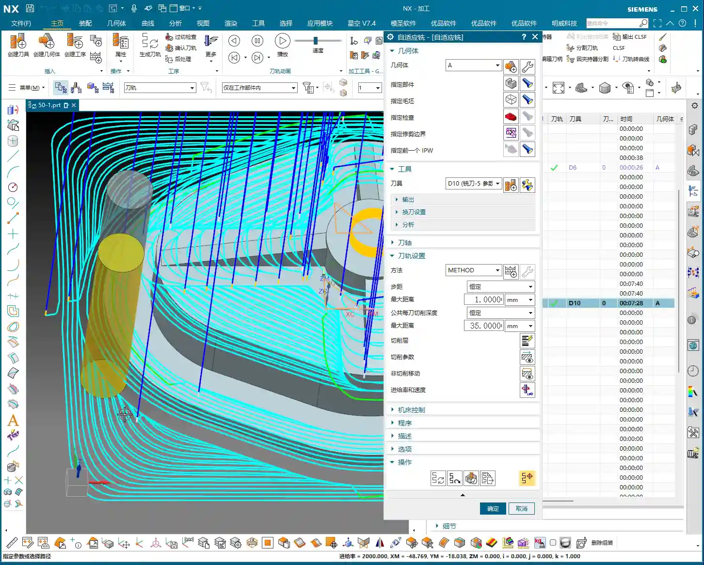
Master Wang: “Take a look at this diagram, especially when performing Corner Cleanup or machining deep cavities. If we stick to the default helical milling strategy, it spirals outwards layer by layer. It looks like it’s clearing the material, but the problem arises at the very end, especially when you reach the center, where it can leave behind a ‘fragile central remnant.’ This thing is like an isolated island, with no support. If the tool sweeps across it, at best it’ll get knocked off, spraying chips everywhere. At worst, it’ll cause tool breakage or even damage the workpiece. This is serious business, understand? Core Pain Point: Default helical milling often leaves a thin-wall ‘fragile central remnant’ in the center area, which can easily shatter, damaging the tool and the part.“

“Hole-Milling Style” Center Material Removal
Master Wang: “So, when you encounter this situation, we need to switch our approach. Just like we mill a hole, we need to ‘mill out’ the material in the center, spiraling from top to bottom. In Siemens NX, we can switch to this mode, and it won’t leave that ‘fragile central remnant’ in the middle. The tool will act like a drill, first plunging to the bottom, then spiraling upwards or downwards to lift and cleanly remove all the remaining material from the entire central area. This method is safe, stable, and good for both the tool and the workpiece. Solution: Employ a ‘hole-milling style’ center material removal strategy to ensure residual material is safely removed from the center outwards, avoiding thin-wall remnants.“

Practical Siemens NX Parameter Optimization Techniques
Cutting Direction and Toolpath Generation
Master Wang: “Next, let’s talk about toolpath direction. In Siemens NX dynamic milling, there’s a ‘Transform Direction’ option. By default, it’s usually climb milling, where the tool’s cutting direction is the same as the feed direction, ensuring stable cutting and good chip evacuation. But if you set this percentage to 50%, it will switch between climb milling and conventional milling. The toolpath might look ‘prettier’ and run ‘smoother,’ reducing the number of retracts. But old Master Wang here has to warn you, this is not recommended for all materials. For some materials, like titanium alloys and superalloys, conventional milling can lead to work hardening, increased tool wear, and even chipping. So, unless you have absolute confidence in the material properties and tool performance, it’s generally advisable to maintain a single climb milling direction to ensure machining stability. This is a lesson from experience that textbooks might not emphasize.”
NX Parameter Path: Connect -> Tool Path -> Transform Direction (Step %)

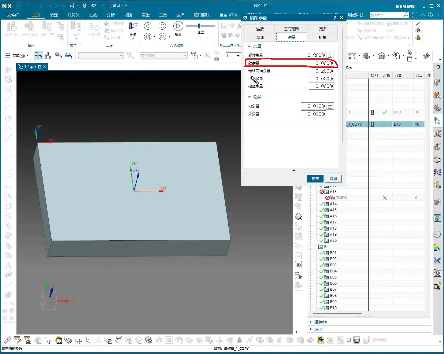
Non-Cutting Moves: Refined Control of Retract Height
Master Wang: “Next up are non-cutting moves, which we often call ‘retracts’ or ‘lifts.’ In 2D dynamic milling, I’ve talked about ‘Retract Distance’ and ‘Large Distance.’ In 3D, these two parameters are integrated. Specifically, this ‘Rapid Transfer‘ parameter controls the tool’s retract height when moving between adjacent cutting regions. The default value might be set very high, say 100mm. Think about it, if you retract that high for every transfer, your air cutting time becomes excessive, completely wasting efficiency! Unless the raw stock is unusually tall or there are obstacles, I generally recommend setting it to 3mm or 5mm, or even 1mm is often enough. Go as low as possible; that’s how you squeeze out efficiency.”
NX Parameter Path: Non-Cutting Moves -> Rapid Transfer -> Retract Height


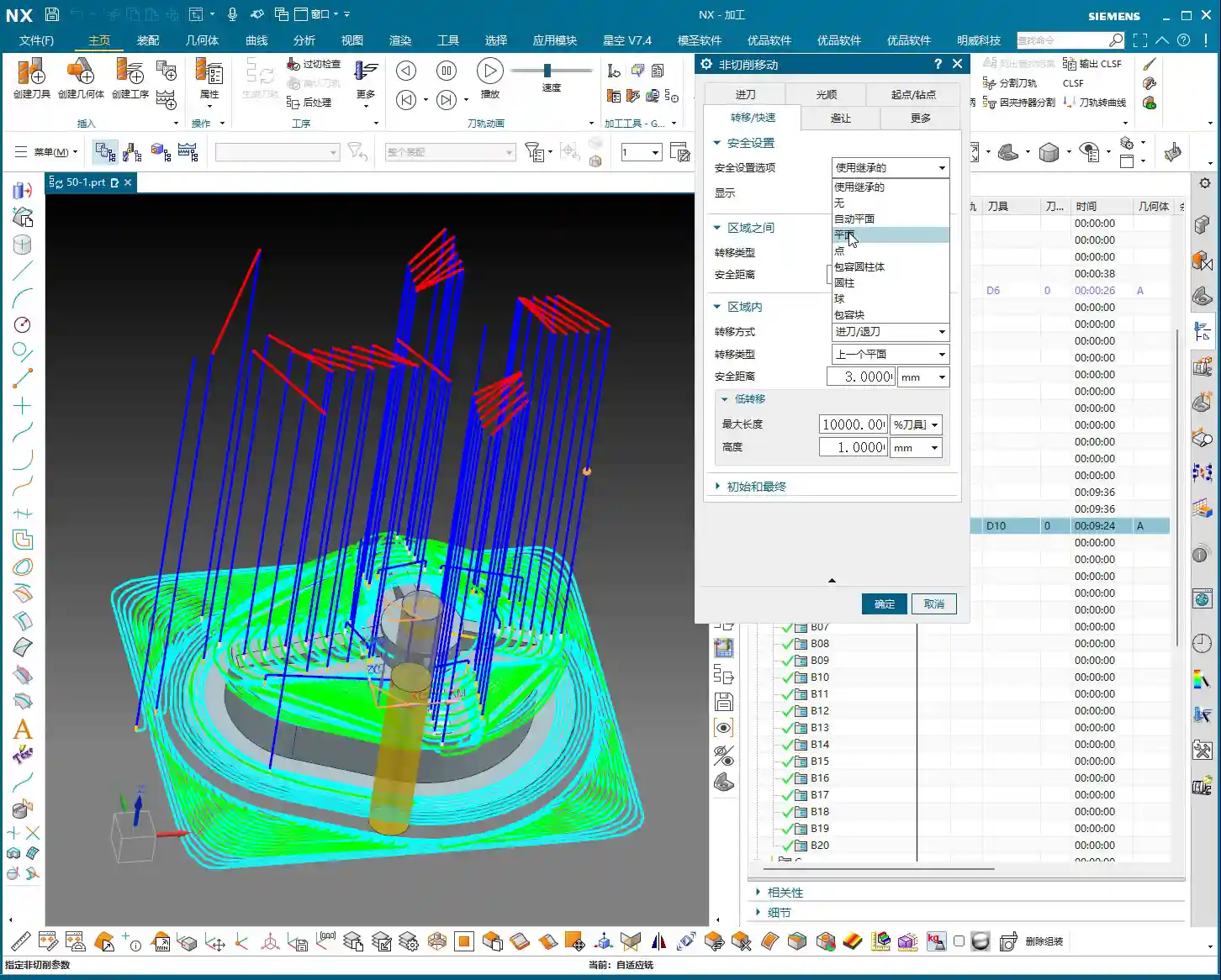
Safe Initial/Final Retracts and Efficient Intermediate Transfers
Master Wang: “But there’s a pitfall here, listen closely! If you set the ‘Rapid Transfer’ too low across the board, then the retracts for the very first cut and the very last cut will also be low. If the safety clearance isn’t sufficient for the first cut onto the workpiece, you’re looking at a collision. The same goes for the last cut: if the program finishes with the tool at a low position, an operator might accidentally bump it. So, we need to balance safety and efficiency. The solution is this: In ‘Non-Cutting Moves,’ find the ‘Initial‘ and ‘Final‘ retract settings. Change their type from ‘Relative to Plane’ to ‘Absolute,’ and then set both to 100mm (or a higher safe value). This way, at the start and end of the program, the tool will safely retract to a high position, while intermediate rapid transfers will use our defined low retract (e.g., 3mm), ensuring efficiency. Now that’s experienced operating!”
NX Parameter Path: Non-Cutting Moves -> Initial/Final -> Type changed to “Absolute” -> Distance set to 100
Advanced Application: Creating In-Process Workpiece (IPW)
Understanding the Function and Significance of “Create Workpiece”
Master Wang: “After the program runs, you might need to machine the next operation, or perhaps flip the part for machining. Siemens NX has a very practical function here called ‘Create Workpiece.’ After a simulation, you can click ‘Create,’ and it will generate an independent geometric body representing the remaining material after the current program is finished. What’s the use of this, you ask? It’s simple: it becomes the ‘stock’ for your next operation! For example, after milling one side, you generate this workpiece. Then, you flip the part and directly set this generated workpiece as the initial stock for the second side. This avoids repetitive measurements and ensures more accurate data. For multi-sided machining and fine-finishing complex surfaces, this is an absolute game-changer, greatly improving programming efficiency and subsequent machining accuracy!”
NX Function Path: After Simulation -> Create (Create Workpiece)
Summary: Pitfall Avoidance Guide
- Beware of the “Fragile Central Remnant”: When dynamic milling deep cavities or performing Corner Cleanup, pay close attention to whether the toolpath might leave a “fragile central remnant” of material in the center area. This residual material is extremely unstable and can easily be knocked off by high-speed tool cutting, leading to tool breakage, workpiece damage, or even safety hazards. Always switch to a “hole-milling style” or similar strategy to ensure safe removal of central residual material.
- Don’t Blindly Set Retract Height: Never allow the tool to retract too high during intermediate rapid transfers; otherwise, excessive air-cutting time will severely reduce efficiency. Based on actual conditions, set the ‘Rapid Transfer‘ to a low value of 3-5mm, or even 1mm, to minimize air time and boost overall efficiency.
- Initial and Final Safety Are Non-Negotiable: When setting intermediate transfer retracts, remember to separately configure the ‘Initial‘ and ‘Final‘ retracts to a safe height (e.g., 100mm). This ensures the tool starts from a safe high position at the beginning of the program and safely retracts from the workpiece at the end, preventing collision risks due to low-position entry or low-position program completion.
- Cleverly Utilize Workpiece Linking: For multi-operation or multi-sided machining, you must use the ‘Create Workpiece‘ function after simulation. Generating the remaining material from the current operation as the initial stock for the next operation will significantly improve the accuracy and efficiency of subsequent programming. This is an essential skill for complex part machining.
- Cutting Direction is Not Trivial: Switching between climb milling and conventional milling should not be done casually. While mixing both directions might make the toolpath appear “prettier,” conventional milling can lead to work hardening and rapid tool wear when machining special materials. Until thoroughly validated, maintaining a single climb milling direction is often more stable and safer.
👤 About the Author:
The author is a veteran CNC machining professional with 15 years of industry experience, specializing in UG NX programming. This article is an original work representing personal practical insights.

⚠️ Copyright Notice: Unauthorized reproduction or distribution without prior communication is strictly prohibited.