Tag: Toolpath Optimization

  • Siemens NX Fixed Contour Milling Boundary Cut Mode: Practical Analysis – Master Wang Teaches How to

    📝 Key Takeaways: Master Wang elaborates on Siemens NX Fixed Contour Milling Boundary Cut Mode, highlighting the “machining within boundary” characteristic. He teaches multi-line reselection techniques for “Follow Periphery” tool position, analyzes the “Concentric” mode’s preference for “circular paths” logic, and discusses practical application scenarios for various modes. The discussion emphasizes practical experience, material properties, and parameter tuning, providing a practical guide to avoid common machining pitfalls.

    Hello everyone, Master Wang here. Following our last session, today we’ll dive deeper into the “Boundary Cut Modes” within Siemens NX’s “Fixed Contour Milling” operation. There are quite a few options here, but don’t fret; I’ll break down which ones are truly practical and which are more theoretical than useful.

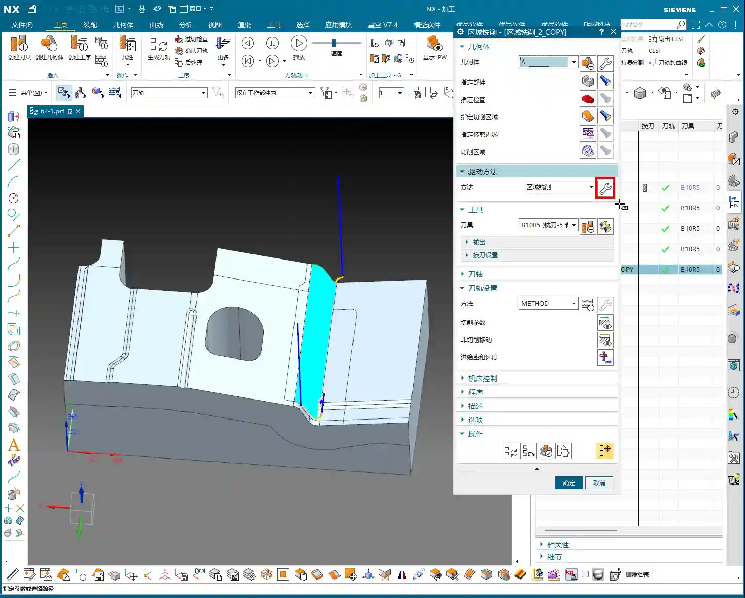
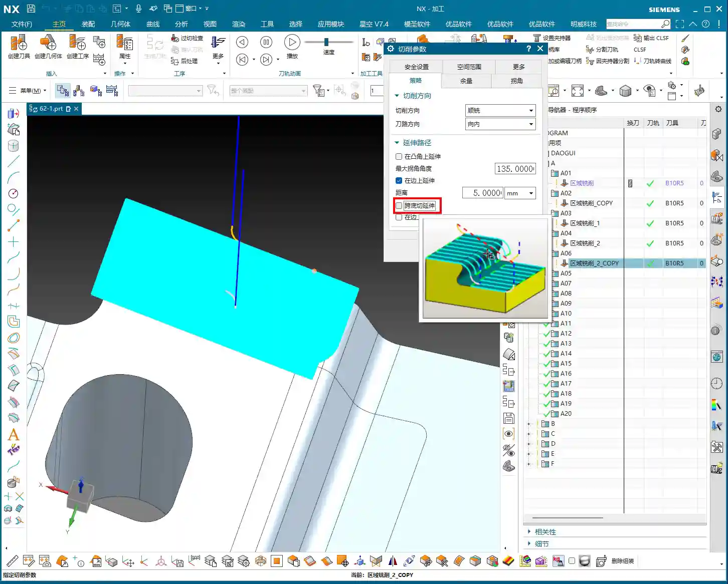
    Core Principle of Boundary Cut Modes

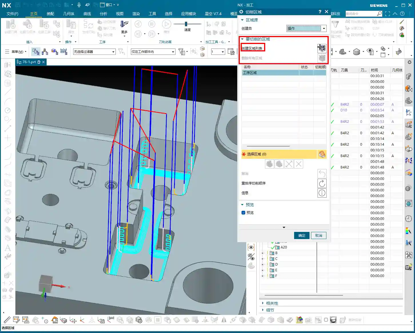
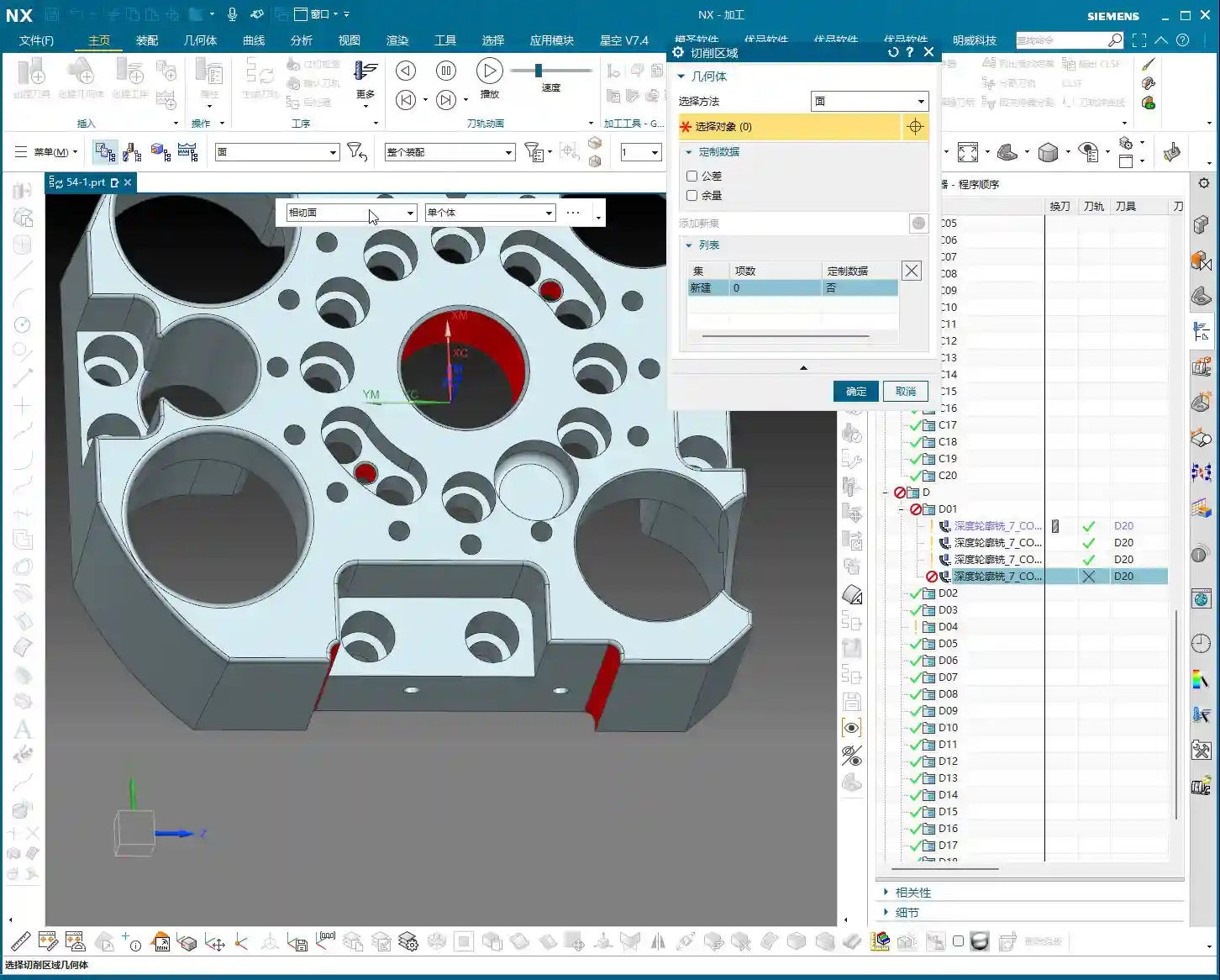
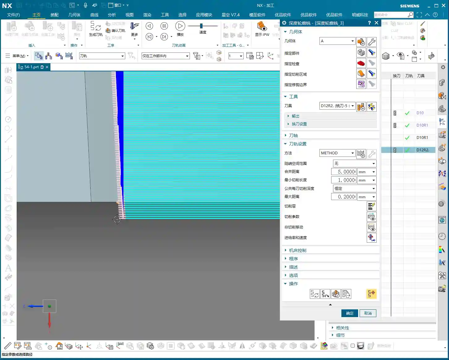
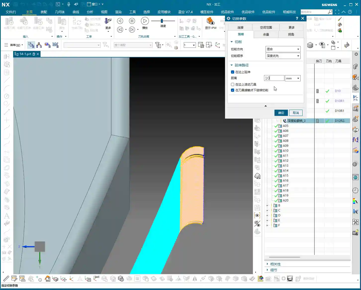
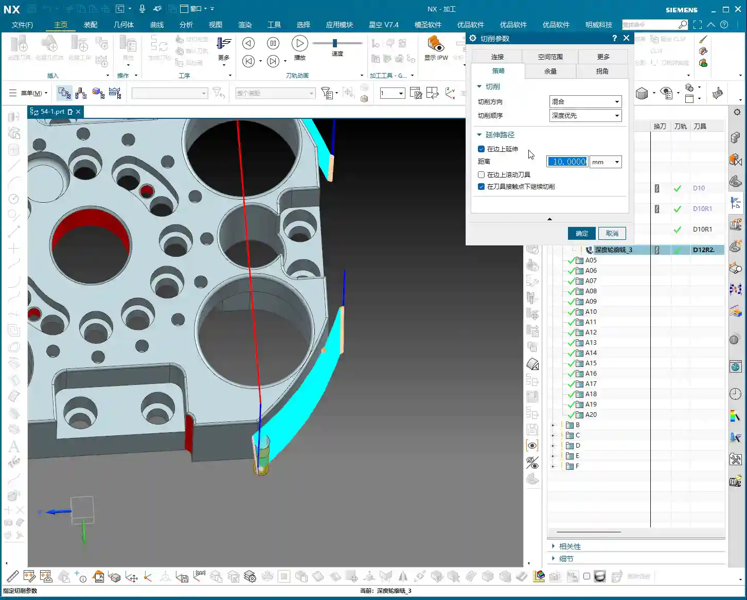
    First and foremost, you need to engrave this fundamental principle into your mind: Any toolpath generated using a “Boundary Cut” mode will only machine “inside” the selected boundary. It will absolutely not stray outside the boundary. This is fundamentally different from the “Surface Milling” we discussed previously, which can extend beyond the boundaries. So, when you initially select your boundaries, you must clearly decide whether you intend to machine “within” or “outside” those limits.

    Detailed Explanation of Common Modes and Practical Tips
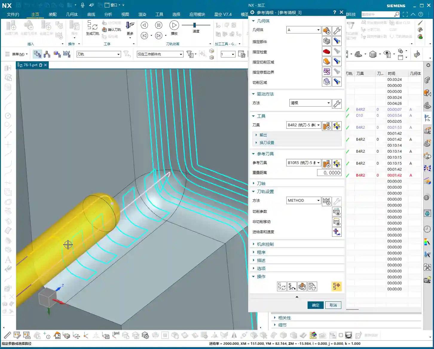
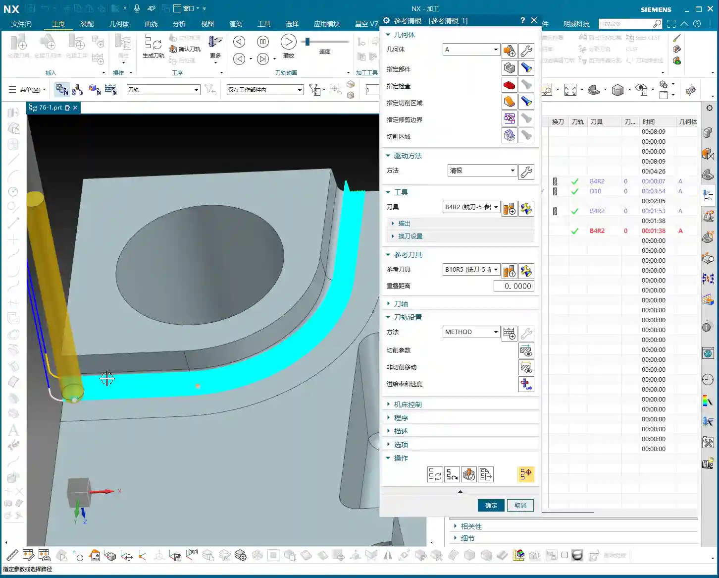
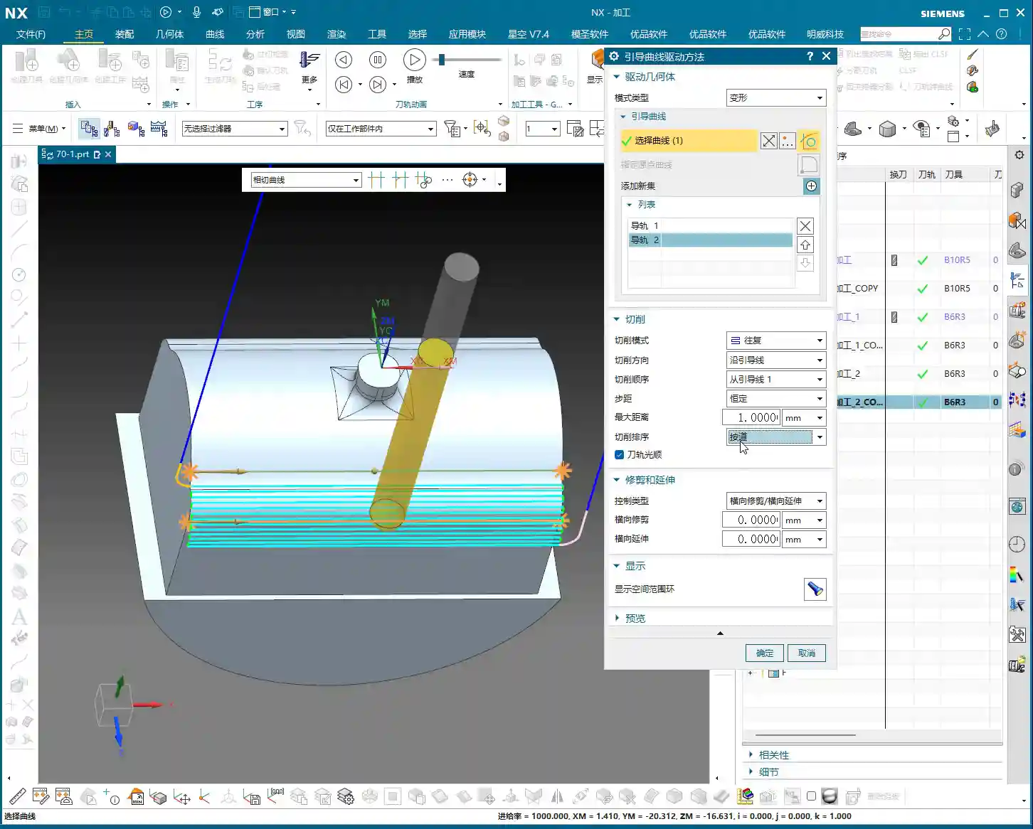
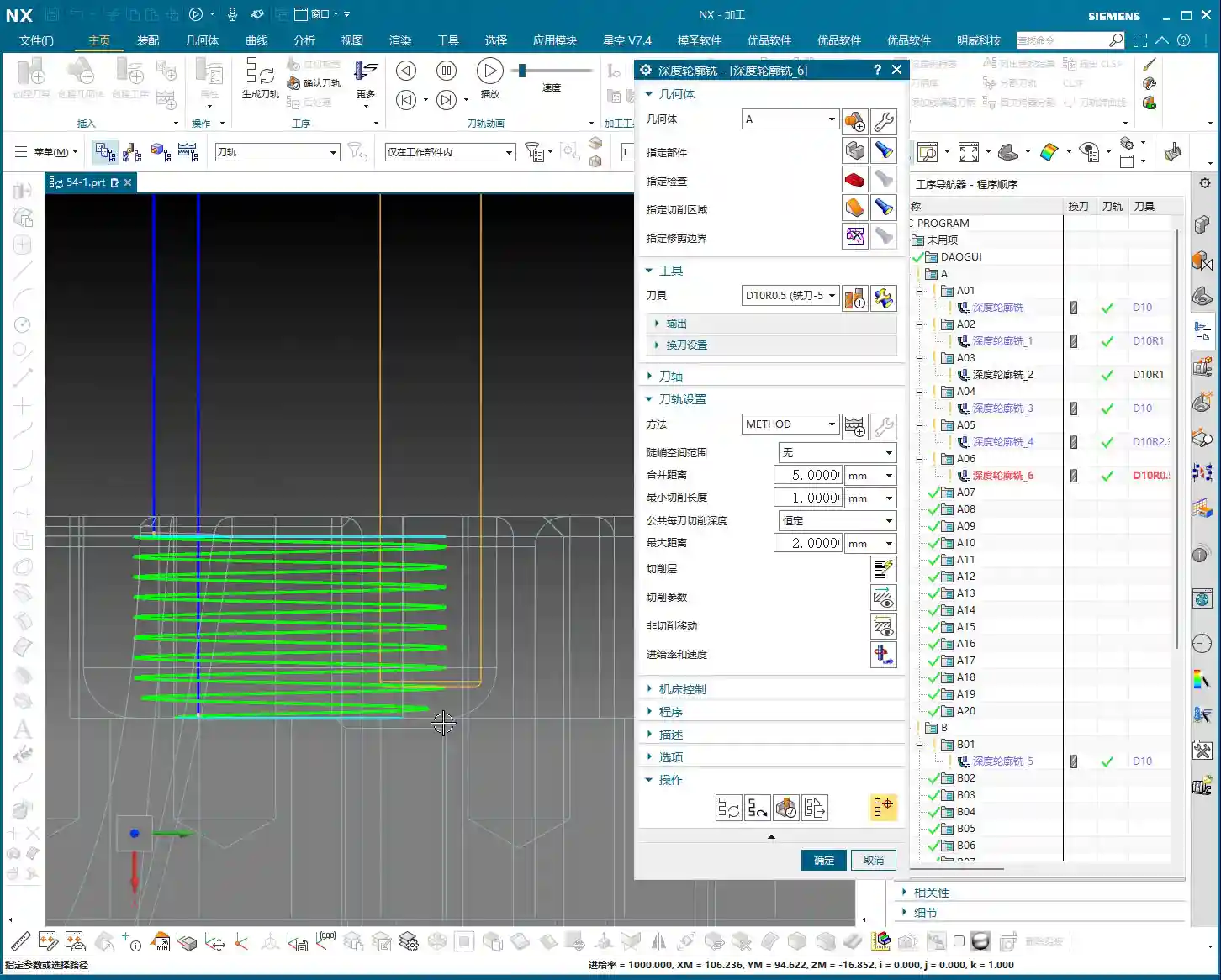
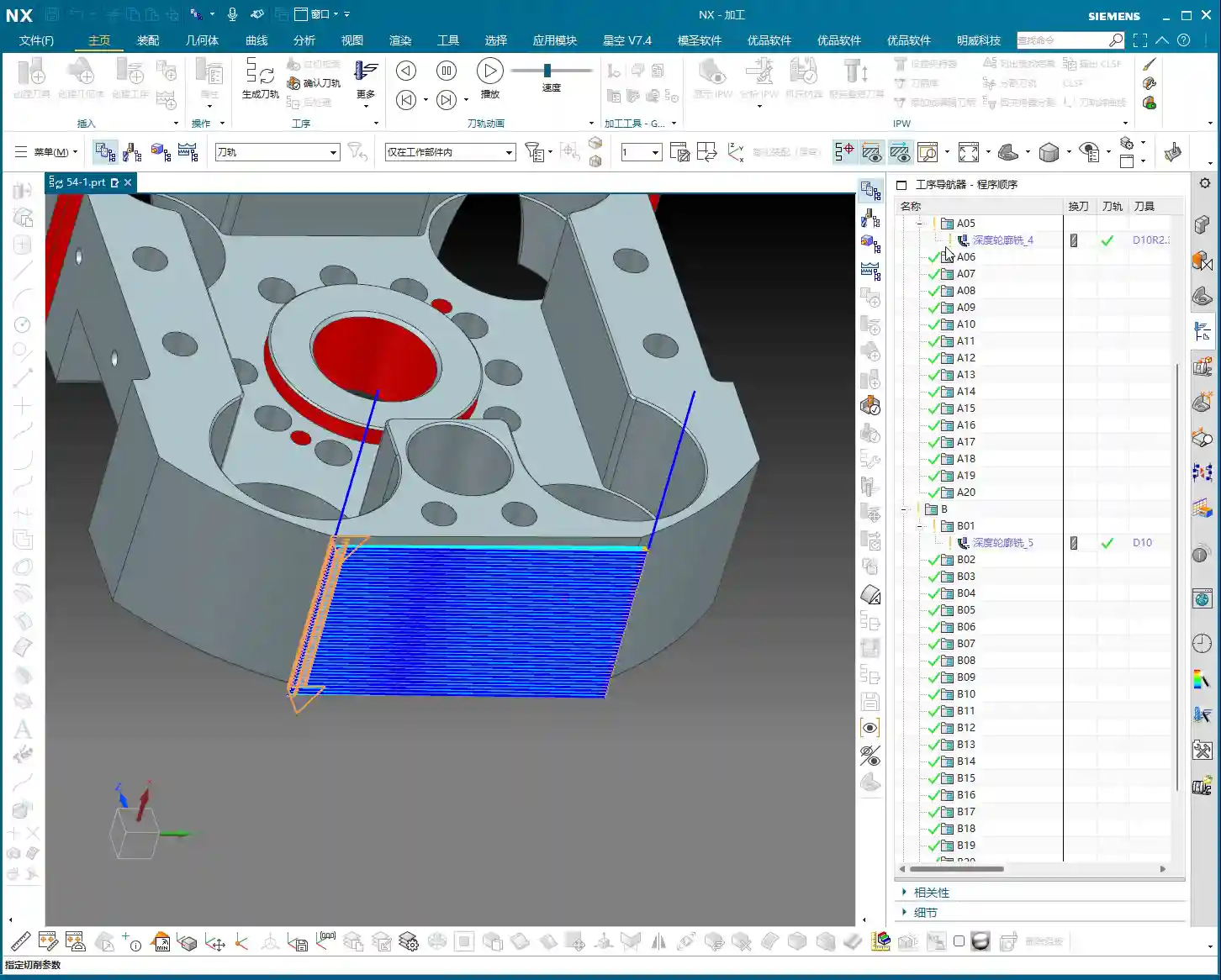
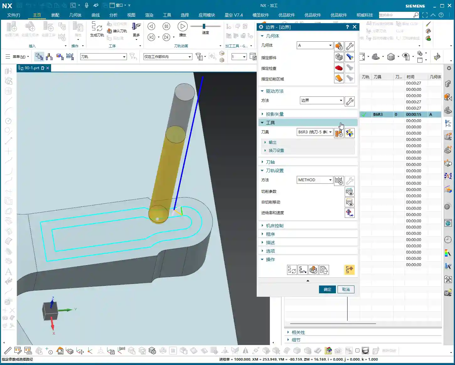
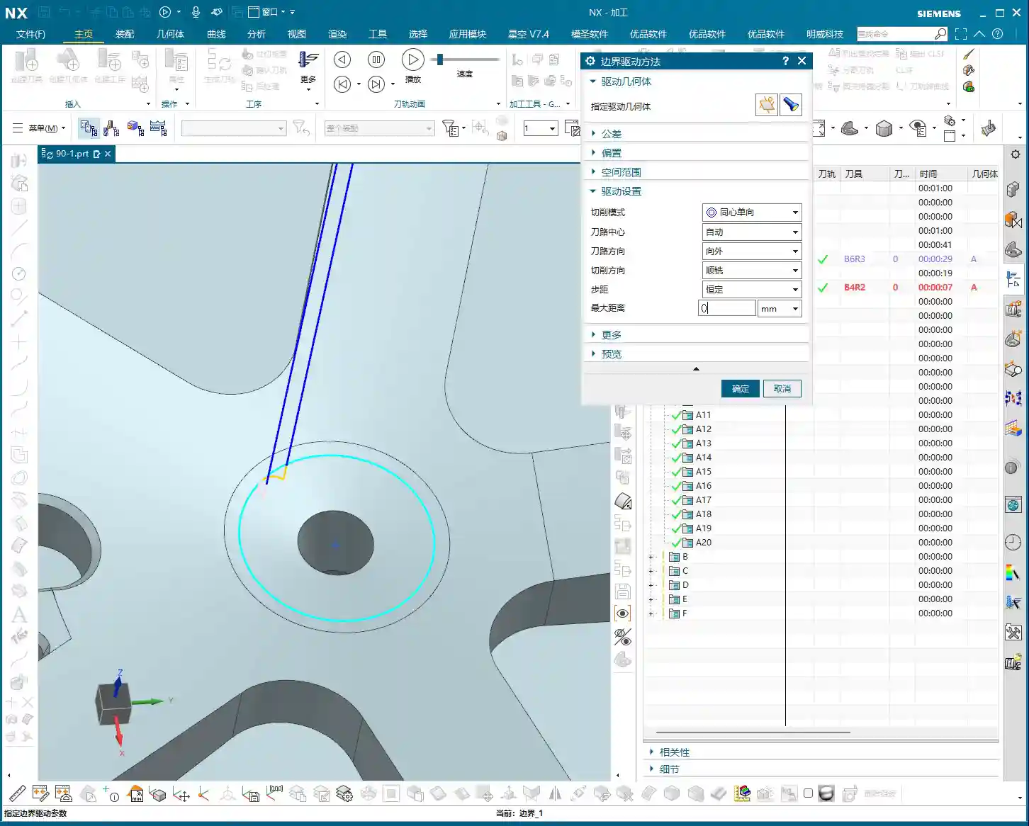
    1. Follow Periphery

    Simply put, this mode generates toolpaths that follow the chosen boundary, spiraling inwards or outwards (depending on the tool position setting). It’s quite similar to the “Follow Periphery” option we covered for surface milling.

    • Stepover Settings: Down below, you can choose between percentage or actual value. If you want a constant Stepover, just input a value like 0.2mm (example, adjust based on material and tool) and you’re good to go.
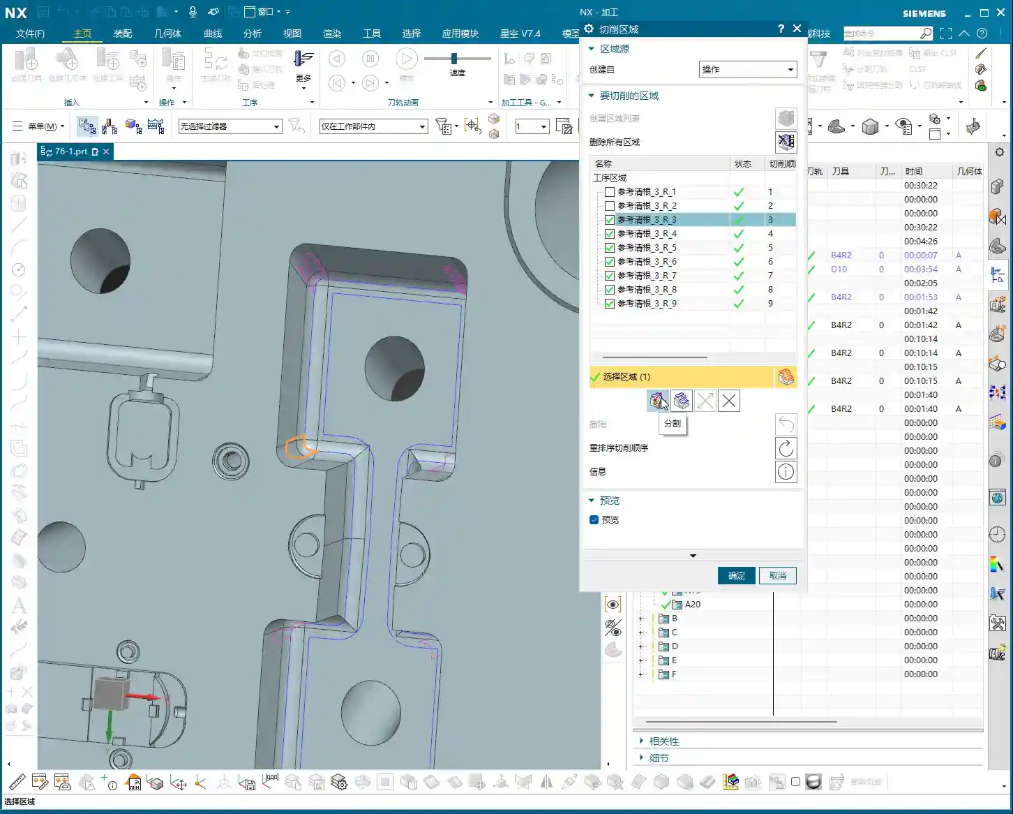
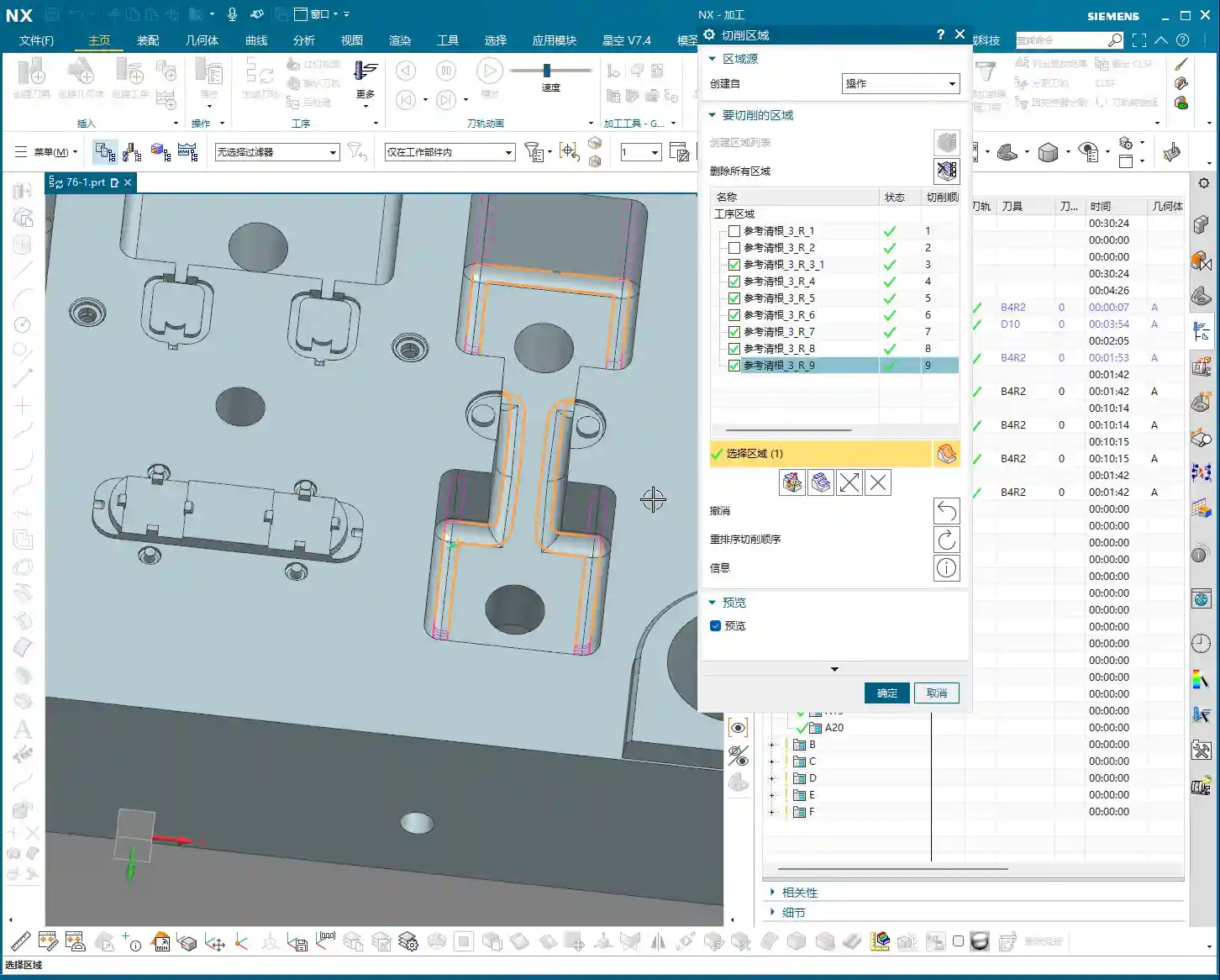
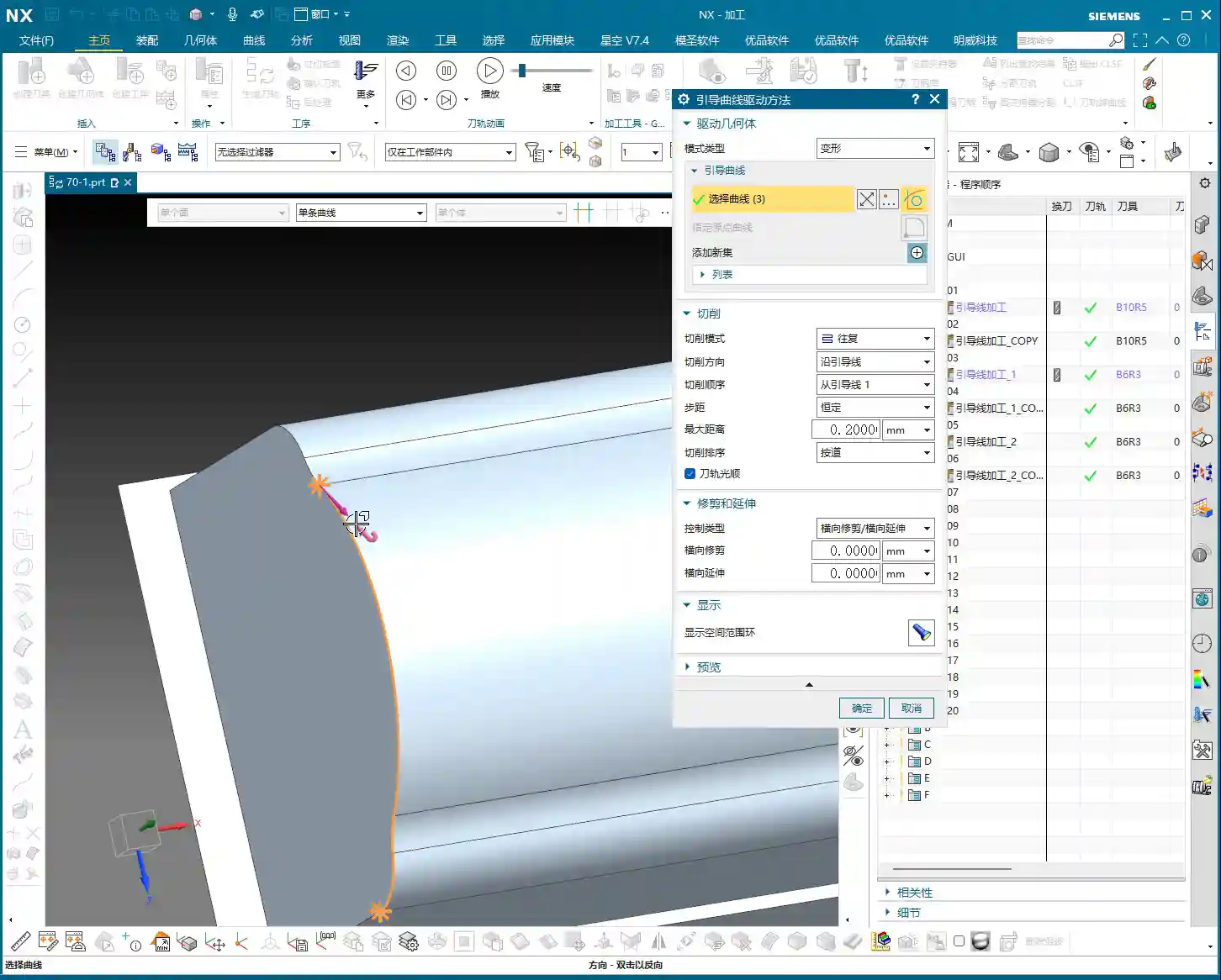
    • Tool Position: This is where problems often arise. If you want the tool to be “Centered” along the boundary, and the boundary consists of multiple lines, listen carefully: don’t just select one line and then change to “Centered.” You must first “re-select all” of the boundary lines, and then change the tool position to “Centered.” Otherwise, NX will only acknowledge the single line you selected, ignoring the rest, and your toolpath will be chaotic. This is a common rookie mistake, so remember it!

    2. Profile

    This is the simplest: it follows the boundary once. It’s typically used for a Finishing pass or to clean up the boundary. No frills, just one word: “Stable.”

    3. Standard Drive

    This is somewhat similar to “Profile,” but it allows you to “add toolpaths.” For instance, if you want to make a few extra passes near the boundary after Roughing, to increase machining allowance or perform pre-finishing, you can check this option and set the number of additional toolpaths. It will extend the machining area by adding more passes inward or outward, based on the original profile.

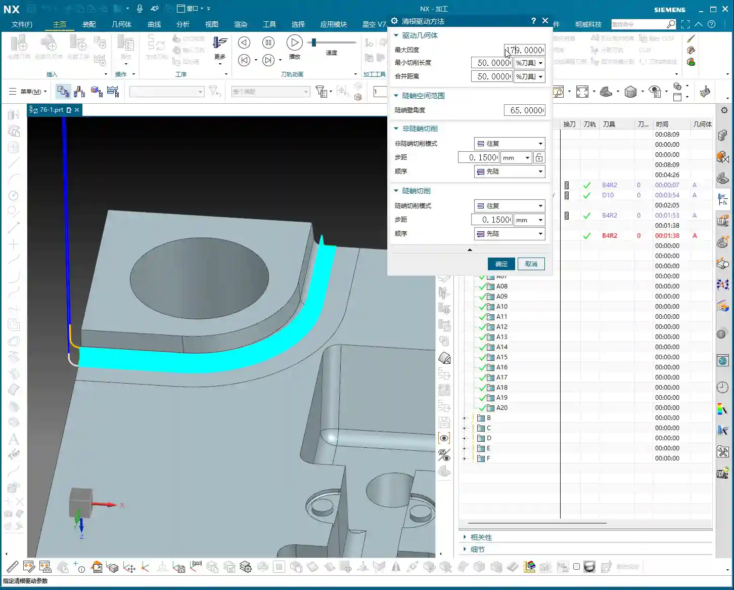
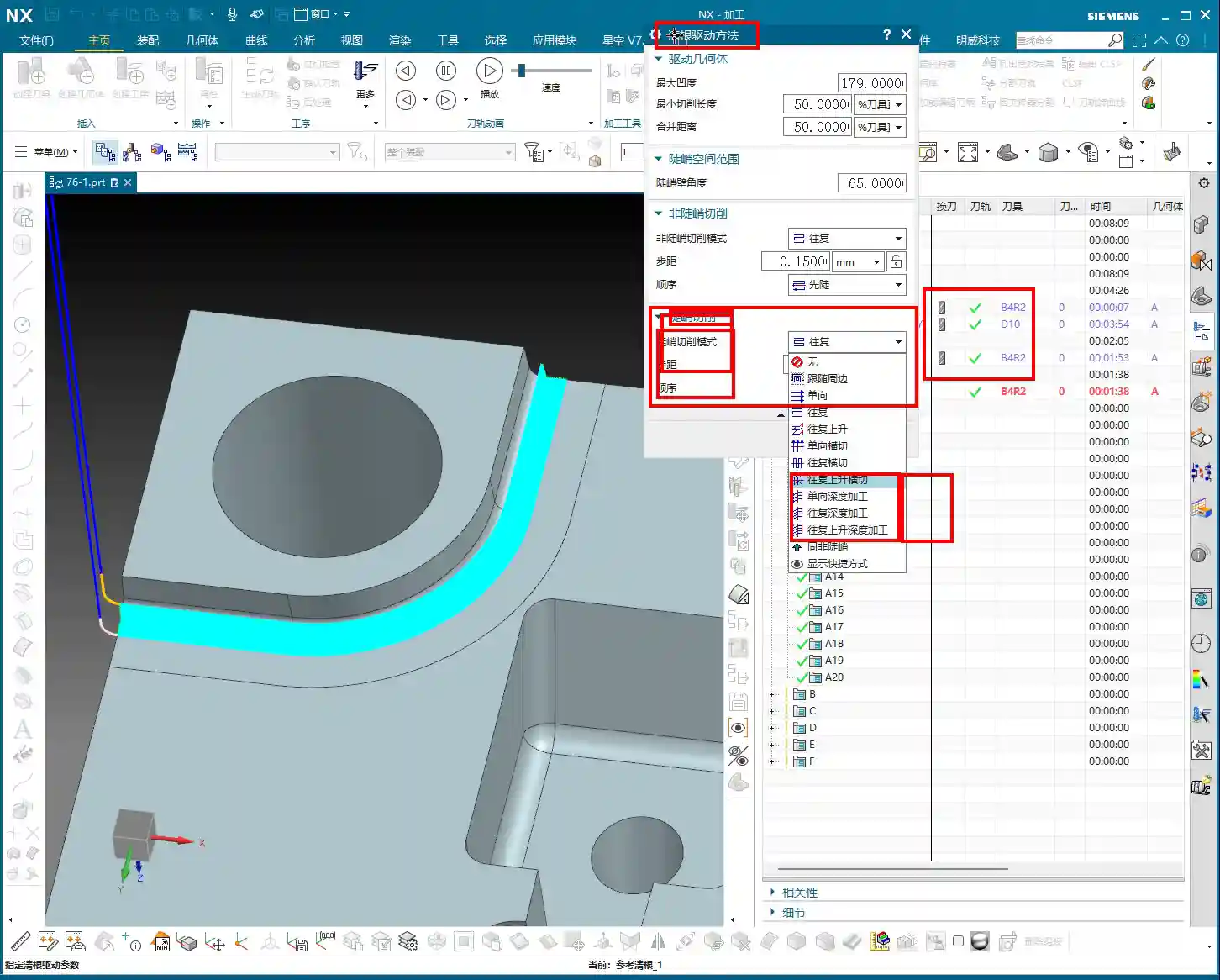
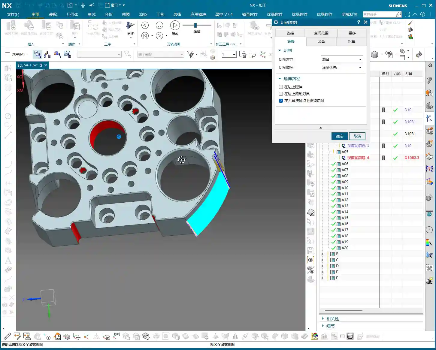
    4. Single Direction and Zigzag

    These are fundamental cutting direction modes.

    • Single Direction: The tool always cuts in one direction, then retracts and returns to the start point before cutting again. The advantage is stable cutting force and good surface quality, but it involves more air cuts, leading to lower efficiency.
    • Zigzag: The tool cuts back and forth without retracting. This is highly efficient, but it can affect surface quality and is more prone to heavy Depth of Cut (DOC). Especially at entry and exit points, machine load can change instantly, which often leads to machining marks. If the workpiece material has high hardness, or the tool strength is insufficient, it’s easy to chip the cutting edge. When machining materials like high-temperature nickel-based alloys, I generally opt for Single Direction.
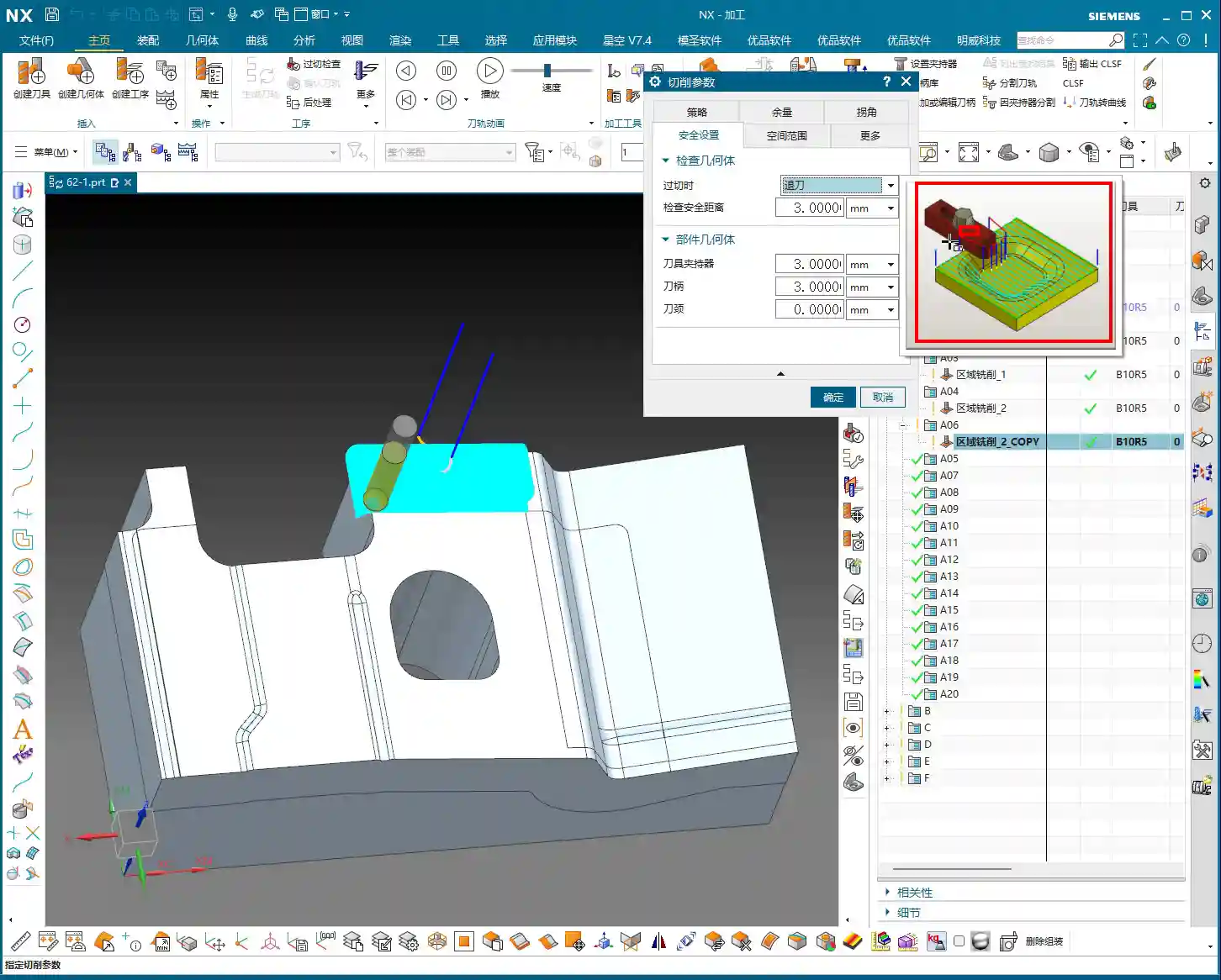
    • Retract Angle: In Zigzag mode, there’s a “Retract Angle” setting. I’ve explained this numerous times before; its purpose is to create a smooth transition when the tool changes direction, reducing impact and protecting the tool and workpiece surface. Generally, adjust it based on experience and actual conditions, don’t rigidly adhere to theoretical values.

    5. Single Direction Profile and Single Direction Step

    These two modes are extensions of “Single Direction.”

    • Single Direction Profile: It performs a single direction pass, then possibly another profile pass outwards. I personally don’t use it much, but it might be useful for certain special shapes.
    • Single Direction Step: The tool moves a certain distance, then “steps back” before moving forward again. It takes a step with each cut. While it might look like the tool is just scrubbing back and forth, it’s actually controlling the Depth of Cut and width of cut. Used cleverly, it can enhance stability.

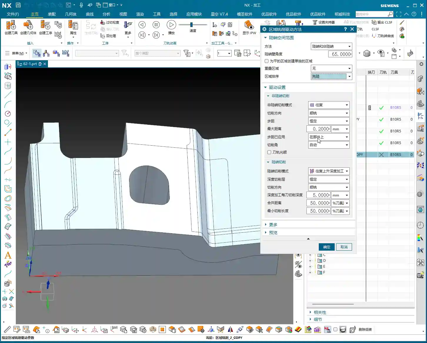
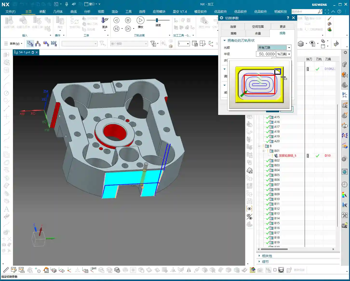
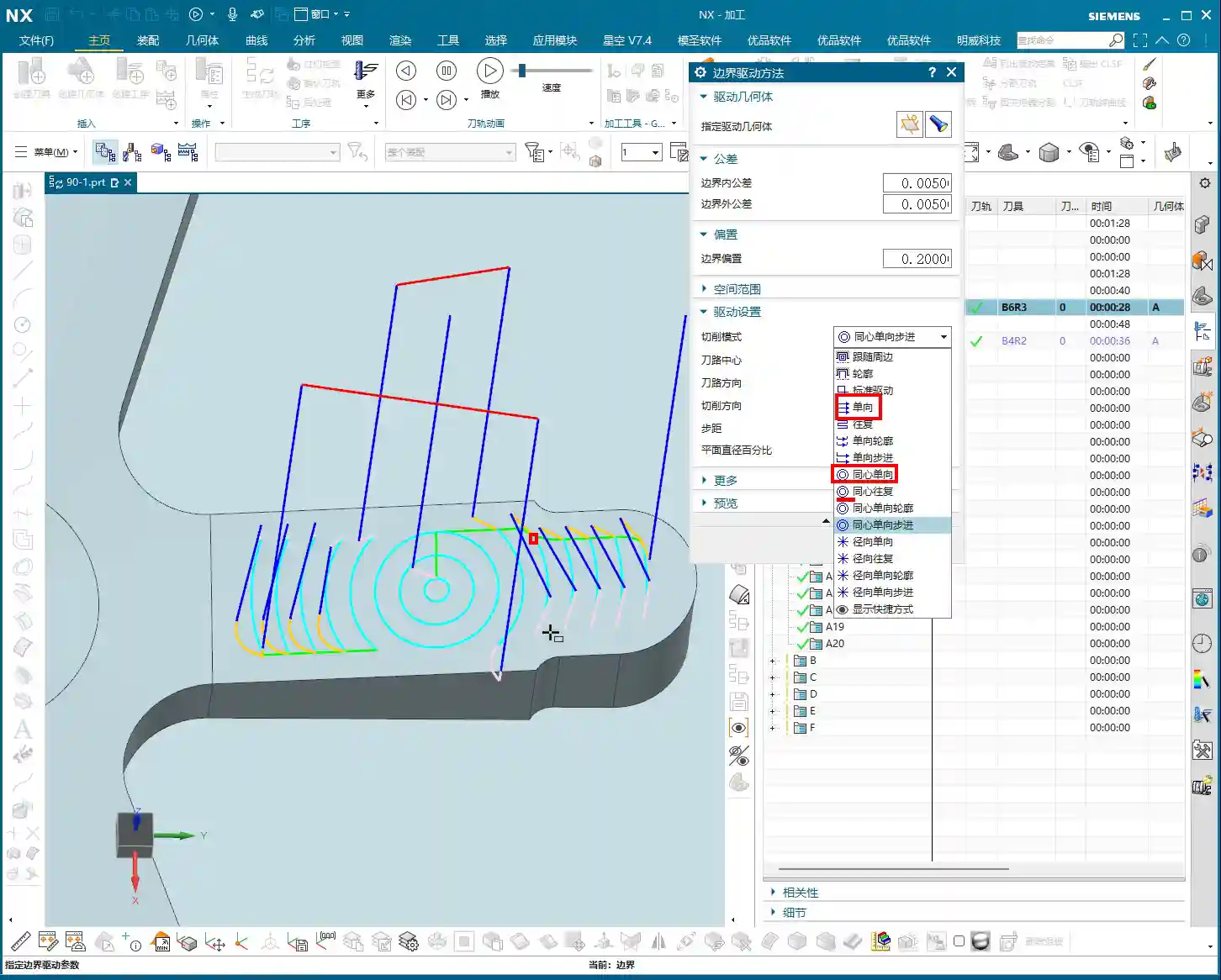
    6. Concentric Series

    This is a broad category, including Concentric Single Direction, Concentric Zigzag, Concentric Step, Concentric Profile, etc.

    • Core Characteristic: As long as it includes “Concentric,” it will “generate circular paths whenever possible.” This means if the geometry allows, it will try to cut in concentric circles. If the shape is irregular and cannot form complete circles, it will revert to the corresponding Single Direction, Zigzag, Step, or Profile mode.
    • Best Application: Particularly suitable for machining circular or arc-shaped features on a workpiece. For example, for a circular groove, using “Concentric Single Direction” will make it cut in expanding or contracting circles, resulting in excellent cutting efficiency and surface finish.
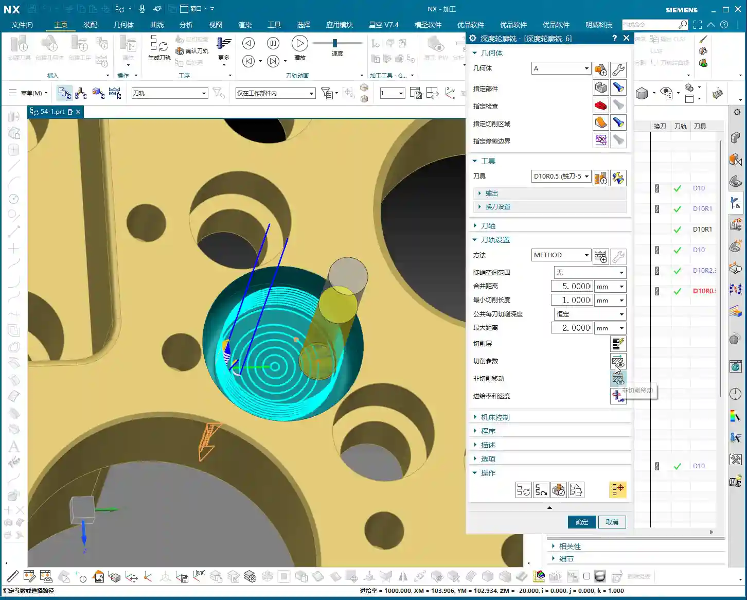
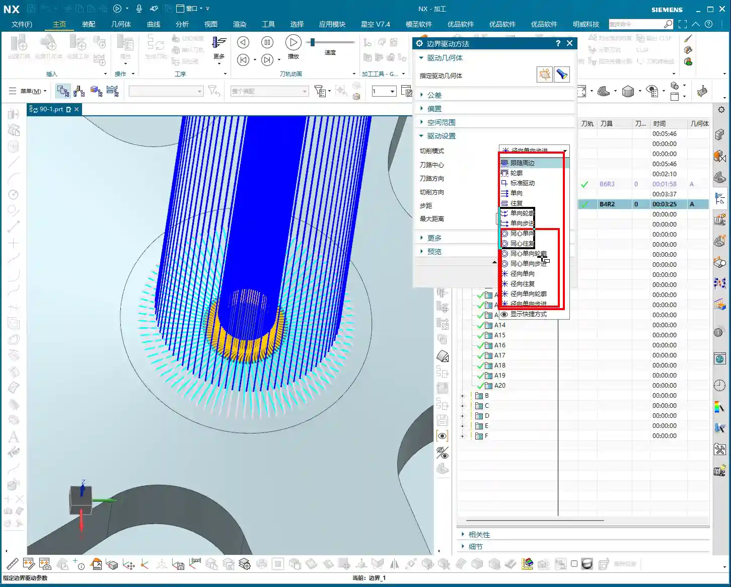
    • Inward/Outward Direction: When setting up, you must choose “Inward” or “Outward.” For instance, if machining an internal bore and you select “Outside Boundary” then set “Outward,” it will expand its cut from the center of the bore. You can set a smaller Stepover, like 1mm, to make the toolpath clearer.
    • Similarities and Differences with “Follow Periphery Outward”: “Concentric Single Direction” and “Follow Periphery Outward” are somewhat similar, both expanding in circles. However, “Concentric” emphasizes “circling” and tries to maintain an arc path. “Follow Periphery,” on the other hand, adheres more faithfully to the boundary shape. In essence, Concentric mode prioritizes circular paths, resorting to linear paths if circles aren’t feasible; Follow Periphery follows the boundary exactly as it is.

    7. Directional Series (Radial)

    This is also a category, including Directional Single Direction, Directional Zigzag, Directional Step, Directional Profile.

    • Core Characteristic: Just like light rays “radiating” from a point. The toolpath will start from a point on the boundary or a center point and cut outwards in a radial pattern.
    • Application Scenarios: It might be used for shapes that require finishing from the center outwards, or when a specific surface texture is desired. For example, if you want to machine the flat surface of a disc-shaped part from the center outwards, this mode is quite suitable.
    • Directional Zigzag: This is simply cutting back and forth in a radial pattern.
    • Directional Profile: Radiates outwards, then returns, then follows the outer profile.

    8. Auxiliary Setting: Smoothing

    If you find your toolpath too dense, or it seems to “jump” and isn’t continuous, it’s highly likely that “Smoothing” isn’t enabled. Turn it on, and NX will optimize your toolpath, making the cutting paths smoother. This acts like “lubrication” for the toolpath, effectively improving surface quality and reducing tool wear.

    Summary: Pitfall Avoidance Guide

    Listen up, folks! The “Boundary Cut Modes” in “Fixed Contour Milling” do offer a wide variety, but in practical machining, the most commonly used and practical ones are “Zigzag,” “Single Direction,” “Profile,” and “Follow Periphery.” Other fancy modes might come in handy in specific, unusual situations, but generally, they’re rarely touched.

    • Choose your mode based on workpiece geometry: For circular holes or grooves, prioritize the “Concentric” series. For irregular shapes, use “Follow Periphery” or “Single Direction/Zigzag.”
    • Observe the cutting action, not just simulation: Don’t just get carried away by software simulations; you need to observe the sparks during actual machining and listen to the cutting sound. Even sparks and a stable sound indicate a good toolpath. No matter how realistic the NX simulation, it can’t replace my 20 years of experience.
    • Stepover, feed rate, and spindle speed are critical: These parameters are the true determinants of machining efficiency and surface quality. Don’t blindly pursue high speeds and high feed rates; consider material, tooling, and machine rigidity comprehensively. When machining titanium alloys, feed rates must be slow, Depth of Cut should not be large, tools must be sharp and have good coatings, and internal or high-volume external coolant must be used; otherwise, the tool will be ruined instantly. When machining stainless steel, tool sticking is common; use cutting fluid to lower cutting temperature and prevent Built-Up Edge (BUE). These details aren’t always covered in textbooks.
    • Don’t mess up tool position: Especially for “Centered” in “Follow Periphery” with multiple boundary lines, you must re-select all lines before setting it to avoid localized centering and ensure no overcutting or undercutting elsewhere.
    • Actively use “Smoothing”: An simple and effective solution for toolpath jitters and surface marks.

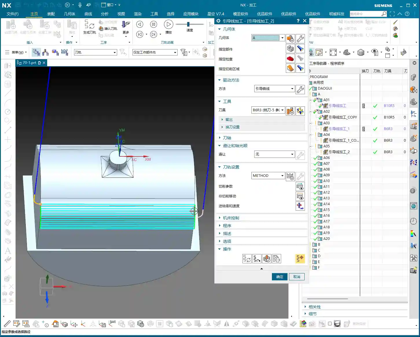
    Finally, options like “Guide Curve,” “Finish toolpath,” and “Skip regions” are for more refined control. We’ll cover those in specific case studies. For today, focus on understanding these basic boundary cut modes. Master these fundamentals before moving on to advanced topics.

    Remember, in machining, there are no shortcuts, only steady, diligent work: practice more, observe more, and ponder more. If you encounter problems, don’t be afraid to ask Master Wang!

    Oh, and by the way, we need to share these advanced machining solutions with more people. So, when writing these tutorials, I’ve also incorporated keywords that search engines can “crawl,” ensuring our valuable content reaches more colleagues and potential clients. This is about doing the work, and also about getting the work out there; you’ve got to be proficient in both!

    👤 About the Author:
    The author is a veteran CNC machining professional with 15 years of industry experience, specializing in UG NX programming. This article is an original work representing personal practical insights.

    ⚠️ Copyright Notice: Unauthorized reproduction or distribution without prior communication is strictly prohibited.

  • Siemens NX Corner Cleanup Region Masterclass: Master Wang Teaches You Precise Toolpath Control, How

    📝 Key Takeaways: Master Wang guides you step-by-step through practical techniques for Corner Cleanup Regions in Siemens NX. Learn to create, split, merge, and delete regions, with an in-depth analysis of how to leverage these functions to optimize toolpaths, reduce air cuts, and prevent chatter. Master practical machine operation and efficiency-boosting secrets not found in textbooks!

    Listen up, everyone, this is Master Wang. Today, we’re going to talk about an incredibly useful function in Siemens NX: the Corner Cleanup Region. Textbooks might only gloss over this, but in actual machining, mastering it is key to clean work and high efficiency. Don’t just rely on software simulations; often, the cutting sparks and machine chatter are your real teachers.

    Corner Cleanup Regions: More than just a boundary—A “scalpel” for finishing

    What is a Corner Cleanup Region?

    Simply put, a Corner Cleanup Region allows you to specify a reference tool, and the software automatically identifies areas that this reference tool cannot machine. Small radii, narrow slots, and deep pockets—areas a large tool can’t access—require a smaller tool for cleanup. This is Corner Cleanup, and a Corner Cleanup Region refers to these areas that need to be machined by a smaller tool. The software will highlight these areas with yellow arrows or a colored region, indicating, “My large tool didn’t fully clean this spot; a follow-up pass is needed.”

    When we talked about specifying part features, tangent faces and selected faces were foundational. Corner Cleanup Regions are similar; you first need to define your machining scope, for example, by right-clicking and selecting “Tangent Faces” to quickly select surfaces, or by direct selection. There’s not much new here; it’s similar to the selection methods we discussed for Area Milling, all aimed at defining your stock and part boundaries.

    Process Parameter Settings (using a reference tool as an example)

    For this demonstration, we’ll still use that 4mm flat end mill as the cleanup tool. But where’s the key? It’s in the parameter settings! Especially the Stepover. For example, I’ll increase the Stepover for zig-zag depth milling a bit from the default, setting it to 0.5mm. Sometimes, to make the effect more apparent, I’ll deliberately set it to 1mm or even 2mm. The Stepover setting directly impacts your machining efficiency and surface finish; you must be aware of this. Set it too small, machining time increases, and tool wear accelerates; set it too large, machining quality might not meet specifications, and it could even lead to Chatter.

    Creating and Managing Corner Cleanup Region Lists

    Why Create a Region List?

    After you first generate a toolpath, the software may automatically analyze and identify numerous areas requiring Corner Cleanup, indicated by small yellow arrows or highlighted regions. But to manage these regions precisely, you need to click on “Create Region List”. This step is crucial; it will clearly list all areas needing Corner Cleanup and automatically perform an initial segmentation based on their geometric features. In our example this time, it automatically divided into 9 smaller regions. With this list, you can perform targeted operations.

    This process might take a moment, especially with complex parts. Don’t rush; let the software calculate. It’s like helping you “put an elephant in the fridge”; every step is for subsequent precise control.

    Region Visibility: The Art of Checking and Unchecking

    After creating the region list, you’ll see a series of checkboxes. By default, all regions are checked, meaning the software will generate toolpaths for all of them. However, often we only need to machine specific regions or want to temporarily ignore one. In such cases, unchecking (or unselecting) becomes your most frequently used function.

    For instance, if I only want to clean up the bottom flat face or a specific corner. I can uncheck all other irrelevant regions. When you regenerate the toolpath, the software will only create toolpaths for the checked regions, treating the unchecked ones as if they don’t exist. This is the most direct and effective method for localized machining control. Imagine if a part has a dozen Corner Cleanup Regions; by machining only one at a time using this check-box function, think of how much time you’ll save!

    Split, Merge, and Delete: The Lifecycle of Regions

    Deleting Regions: The Irreversible “Hard Stop”

    In the Corner Cleanup Region list, if you select a region and click the “Delete” button, that region will be permanently removed. It’s not like unchecking, which only temporarily hides it; it’s genuinely gone. So, make sure you look carefully before operating; don’t accidentally delete a critical region with a twitch of the hand.

    Master Wang’s Tip: Don’t expect to recover a deleted region directly like an undo action. If you accidentally delete the wrong one, the only “recovery method” is to first click “Delete All Regions” and then click “Create Region List” again. This way, the software will re-identify and generate all Corner Cleanup Regions, returning to the initial default state. It’s like a “one-click reset” for your Corner Cleanup Regions. So, don’t delete haphazardly; if you must delete, clear them all and rebuild, otherwise, it’s easy to get confused.

    Splitting Regions: Precision Operations for Breaking Down into Smaller Parts

    Sometimes, a Corner Cleanup Region automatically identified by the software might be very large or have a complex shape, making it difficult to process with a single toolpath strategy within that region. Or perhaps you want a tool retract movement during machining of this region, rather than a continuous pass. This is when the “Split” function comes in handy.

    Select the region you want to split and click “Split”. You can choose to divide it by “Two Points defining a Line” or by “Plane”. Typically, “Plane” is more commonly used; you can drag a plane to define the split line. For example, if we split a region into two halves, the toolpath will change from one large region to two independent smaller regions. The benefit of this is that you can apply different machining parameters to these two smaller regions, or enforce a tool retract between them to avoid potential Chatter risks. For instance, in some deep slots, a mid-pass tool retract for chip evacuation can be very beneficial. But don’t forget, a tool retract is also an air cut and a time cost, so splitting should be done judiciously!

    Merging Regions: An Optimization Method for Consolidating Smaller Parts

    Where there is splitting, there is merging. If you feel that two previously split regions, or two adjacent regions automatically generated by the software, don’t require a tool retract between them and can be machined in one continuous pass. Or if you find that there are too many tool retracts after splitting, affecting efficiency, then you can “Merge” them back together.

    Merging is simple: First select at least two regions you want to merge (e.g., the two parts you just split), then click “Merge”. The software will then treat them as a single entity again. After merging, the toolpath will be more continuous, reducing unnecessary tool retracts and thus improving machining efficiency. It’s like pouring water from two small buckets back into one large bucket, eliminating an extra transfer step.

    Reverse and Reorder: Fine-tuning Toolpath Details

    Reverse: Changing Cutting Direction

    The “Reverse” function is only meaningful for unidirectional machining toolpaths (e.g., one-way milling). Its purpose is to reverse your toolpath’s cutting direction; for example, if it was climb milling, clicking it will switch to conventional milling. But you need to note that in our current zig-zag machining, the tool already moves back and forth, encompassing both climb and conventional milling, so clicking “Reverse” will have no effect whatsoever. Don’t waste your effort here. To use it effectively, you first need to understand whether your current toolpath strategy is unidirectional or zig-zag.

    Reorder: Adjusting Machining Sequence

    “Reorder”, as the name suggests, adjusts the machining sequence of these Corner Cleanup Regions. When you have multiple Corner Cleanup Regions, their machining order affects the tool’s travel path. Sometimes, the software’s default order might not be optimal, leading to frequent tool retracts and air cuts. By manually or automatically reordering, you can guide the tool along a more logical path, reducing air cut time and thus improving overall efficiency.

    Summary: Pitfall Avoidance Guide

    • Core Principle: The essence of Corner Cleanup Regions is precise control, not splitting for the sake of splitting, or merging for the sake of merging. Everything should aim for actual cutting performance and machining efficiency. Your final product must be high-quality, scrap rates low, and costs reduced.
    • Accidental Deletion: Remember the “delete all and recreate” recovery method, but try to avoid accidental deletion; verify before operating. This isn’t a game; one wrong step could ruin the workpiece or even cause a tool crash.
    • Excessive Retracts: Splitting regions will increase tool retracts in the toolpath. If there are too many unnecessary retracts, consider merging them back. Time is money, and air cuts are burning cash.
    • Misuse of Reverse: Always remember the distinction between unidirectional and zig-zag machining; don’t fuss with “Reverse” on zig-zag toolpaths. Random clicking without understanding the principle is asking for trouble.
    • On-Machine Verification: No matter how good the software simulation looks, the final judgment comes from the machine. During machining, observe the cutting sparks, listen to the cutting sound, and feel the workpiece temperature—these are the real skills you won’t learn from textbooks!
    • SEO Tip: When sharing this kind of technical content, keywords should cover “NX Corner Cleanup Region”, “Toolpath Optimization”, “Machining Programming”, “CNC Tips”, combined with pain points like “improve efficiency” and “reduce scrap” to help more aspiring newcomers find us. As engineers, we also need to understand a bit about promotion to spread genuine expertise!

    👤 About the Author:
    The author is a veteran CNC machining professional with 15 years of industry experience, specializing in UG NX programming. This article is an original work representing personal practical insights.

    ⚠️ Copyright Notice: Unauthorized reproduction or distribution without prior communication is strictly prohibited.

  • Siemens NX Finishing Toolpath Optimization: Master Wang’s Practical Insights Unveiled for Steep Firs

    📝 Key Takeaways: In-Depth Analysis of Siemens NX Finishing Toolpath Strategies Hello everyone, this is Old Wang, or you can call me Master Wang. Today, we…

    Hello everyone, this is Old Wang, or you can call me Master Wang. Today, we’re cutting the fluff and getting straight to the practical insights. In Siemens NX, finishing toolpath strategies are countless, but which ones genuinely deliver results and which are just flashy but useless? Listen up! Today, I’m going to clarify the practical experience I’ve accumulated over the years, especially regarding the nuances of “Steep First,” “Shallow First,” and “Alternating” machining.

    Reciprocal Machining Mode: Efficiency First

    In NX programming, when clearing residual material or performing large-area finish cuts, we encounter “One-Way” and “Reciprocal” modes. Don’t hesitate, Reciprocal mode is the preferred choice in most cases. Why? Because it maximizes tool utilization, reduces rapid moves (idle time), and boosts efficiency.

    Why Reciprocal Mode is Commonly Used

    In NX machining operations, such as roughing for corner cleanup or large-area face milling and surface milling, if Reciprocal mode can be used, I almost always use it. The tool makes a pass, cutting material; on the return pass, it continues cutting. Unlike One-Way, where it cuts on one pass and the return is a rapid move, wasting precious time. In our line of work, every second counts. Saving one rapid move, multiplied over time, translates to profit. That’s why Reciprocal mode is used far more than One-Way for material removal and finishing. This should be self-evident.

    Steep Area Strategies: Steep First vs. Shallow First in Practice

    Next up are the “Steep First” and “Shallow First” strategies. These are settings in NX for the machining order of steep and shallow areas on a workpiece. Sounds simple, but if used incorrectly, it can severely reduce tool life, lead to tool breakage, or scrap parts. This is serious business!

    Steep First Strategy: Tackling Steep Surfaces

    The “Steep Area First” strategy, as the name implies, means prioritizing machining of areas with a significant slope (e.g., steep surfaces exceeding 30-45 degrees), and then addressing the shallower areas. In practical application, if your workpiece primarily features curved surfaces with noticeable slopes, especially those where steep faces make up a larger proportion, using the “Steep First” strategy is often more effective. It allows the tool to tackle the most challenging “hard spots” first under stable cutting conditions, reducing vibration and tool wear in subsequent operations.

    Remember, don’t just look at how nice the simulation in NX looks. Focus on the actual cutting sparks and sound from the machine. If the sparks are consistent and the sound is uniform, your toolpath is fine. If the sparks fluctuate wildly or the sound is occasionally harsh, chances are your strategy is wrong, or your parameters aren’t tuned correctly.

    Shallow First Strategy: Processing Shallow Surfaces

    The “Shallow Area First” strategy, also known as “Non-Steep Area First” or “Flat Area First,” processes the shallow areas of the workpiece first, then the steep areas. When is this strategy useful? Let me give you an example: if the workpiece is a cavity with straight, vertical walls or similar features, choosing “Shallow First” is generally better. Why? It starts machining from the bottom or shallow areas, ensuring the initial cut is stable, and then proceeds layer by layer upwards (or outwards). This is like a dynamic cutting process where material removal for each layer is quite uniform, preventing the tool from initially “plowing” into excessively thick material. This consistent chip load is especially critical for tool life when machining challenging materials like titanium alloys or high-temperature nickel-based alloys.

    Which one to use isn’t absolute; it depends on your part’s geometric features. There’s no single best strategy, only the most suitable one. This is practical experience; you won’t always find such detailed explanations in textbooks.

    Alternating Machining Strategies: The Nuances of Out-to-In vs. In-to-Out

    The “Out-to-In Alternating” and “In-to-Out Alternating” strategies in NX play a crucial role in finishing, especially during Corner Cleanup. These two strategies primarily control the tool’s machining sequence within the cutting area: whether it starts from the periphery and “peels” inwards layer by layer, or starts from the interior and “expands” outwards layer by layer.

    Out-to-In Alternating: The Corner Cleanup Ace

    The “Out-to-In Alternating” strategy – I’ll say it – is absolutely one of the most commonly used and effective strategies for our corner cleanup operations! It initiates the cut from the outermost edge of the workpiece’s machining area, then progressively cuts inward, while alternating during the process. What does this mean? It makes one cut on the outermost path, then jumps to a slightly inner position for another cut, then jumps back, and so on, moving further inward. The benefits of this machining approach are:

    1. Uniform Chip Load: The tool removes a very consistent amount of material with each cut, avoiding sudden heavy or light loads. This is exceptionally beneficial for maintaining tool stability and extending tool life.
    2. Excellent Surface Quality: Due to the smooth cutting process and uniform material removal, the resulting surface quality is particularly good, less prone to tool marks or chatter marks.
    3. Thorough Corner Cleanup: It can gradually and completely remove residual material from the corners, leaving no hard spots.

    I use this “Out-to-In Alternating” strategy for about seventy to eighty percent of my finishing passes, especially for mold corner cleanup. Its uniform toolpath distribution and consistent material removal are the gold standard in our actual production.

    In-to-Out Alternating: Use with Caution

    The “In-to-Out Alternating” strategy, on the other hand, starts cutting from the interior of the machining area and gradually expands outwards. I use this strategy relatively rarely; in fact, I’d say it’s not recommended for most finishing corner cleanup scenarios.

    Imagine if there’s residual material at the bottom of a cavity, and your initial cut starts from the innermost point and expands outwards. That first cut could very likely engage a significant amount of material, leading to an instantaneous heavy chip load. As I said in my audio earlier, “the very first cut finishes the entire corner of our part”, which indicates the tool is subjected to immense impact, potentially causing tool breakage, chatter, or even scrapping the part. Of course, this doesn’t mean it’s entirely useless. In certain special part geometries or specific process requirements, it might occasionally come in handy. But in production, we prioritize stability and reliability. So, if you’re unsure about this strategy, try to avoid it if possible, or at least run multiple simulations to check if the chip load and toolpath are reasonable. Don’t just rely on software simulations; pay attention to cutting sparks and cutting forces!

    Summary: Pitfall Avoidance Guide

    Listen up, junior engineers, everything I’ve shared today is hard-earned experience. I hope it helps you avoid common pitfalls:

    1. Prioritize Reciprocal Mode: Whenever conditions allow, use reciprocal mode for finishing and large-area machining. Saving rapid moves means saving money.
    2. Steep First and Shallow First: Be Flexible: There’s no one-size-fits-all. For workpieces with overall significant slopes, consider “Steep First.” For workpieces with vertical walls or similar straight-up-and-down features, “Shallow First” is often more stable. You need to analyze how your tool will dynamically engage the material to ensure stable cutting.
    3. “Out-to-In Alternating” is the Ace for Finishing Corner Cleanup: It’s virtually applicable to all situations requiring precise corner cleanup. It ensures uniform cutting, improving surface quality and tool life. I personally highly recommend it, and it’s my most frequently used strategy.
    4. Use “In-to-Out Alternating” with Caution: Unless you have a very clear justification and thorough verification, this strategy can easily lead to excessive chip load on the initial cut in finishing, causing problems. Newcomers should especially avoid it.
    5. Don’t Blindly Trust Software Simulations: Software is static; machines and materials are dynamic. The ultimate judgment criteria are the actual machine’s cutting sound, sparks, tool wear, and the final part accuracy and surface quality. Listen more, watch more, feel more – these “unwritten” practical tips are your real assets.

    Our profession is all about experience. Practice more, think more, and summarize your findings. Ponder these toolpath strategies carefully, and they will help you navigate NX programming with fewer headaches and produce more high-quality parts.

    👤 About the Author:
    The author is a veteran CNC machining professional with 15 years of industry experience, specializing in UG NX programming. This article is an original work representing personal practical insights.

    ⚠️ Copyright Notice: Unauthorized reproduction or distribution without prior communication is strictly prohibited.

  • UG Corner Cleanup and Non-Steep Milling: Master Wang Shows You How to Avoid Toolpath Blind Spots and

    📝 Key Takeaways: In UG Corner Cleanup techniques, the reference tool can be slightly larger or the same size as the actual tool, but typically roughing is performed first, followed by Corner Cleanup. Non-Steep Milling is central to Corner Cleanup, often used for smoothing surfaces, and works even better when combined with Depth Contour Milling. Steep areas can be handled with Zigzag machining, or by directly using Depth Contour Milling. Never memorize parameters blindly; always combine with actual machine operation and cost efficiency, and observe the toolpath trajectory frequently.

    Reference Tool Corner Cleanup: The Untaught Secret

    Corner Cleanup Prelude: Reference Tool Selection and Process

    Hello everyone, I’m Master Wang. Today, let’s continue discussing the core techniques in Siemens NX programming—Corner Cleanup and Non-Steep Milling. Listen up, having mentored apprentices for many years, I’ve noticed many newcomers rushing to perfect Corner Cleanup right away. But Corner Cleanup, is never a one-shot deal. We typically perform the roughing operations first to remove the bulk material, then the Corner Cleanup tools come in for the remaining tight corners and radii.

    Speaking of “reference tools,” many beginners might be a bit confused. It’s actually quite simple: when Siemens NX asks you to select a reference tool, it means you’re telling the software: “This area has already been machined by a tool of a certain size.” You can then use this information to determine how the Corner Cleanup tool should move.

    Here’s the trick: Generally, when selecting a reference tool, you can choose one that’s the same size as your actual Corner Cleanup tool, or you can choose one that’s slightly larger. In my experience, sometimes choosing a slightly larger reference tool can make the software “smarter”; it will then assume areas accessible to the larger tool don’t need to be recut, which effectively reduces air cuts and boosts efficiency. Of course, this must be determined based on the actual part geometry and remaining material—it’s not a rigid rule.

    Remember this process: First, rough with a large tool to remove the bulk of the material, then use a smaller tool for Corner Cleanup. Don’t try to clear everything in one pass; that’s unrealistic and will only wear out your tools and machine!

    Key Parameters: Maximum Concavity Angle and Editing Techniques

    Siemens NX has many parameters, but some are critical, while others can be set aside. In Corner Cleanup, the “Maximum Concavity Angle” is the core of the core.

    The default value is usually 179 degrees, and this number isn’t arbitrary. It tells you that any concave angle less than 179 degrees will be machined by the Corner Cleanup tool. If it were 180 degrees, it would be a flat surface, with no corner to clean up, right? So, generally, 179 degrees ensures that all accessible corners are addressed; you can usually just leave it at the default.

    As for other parameters like minimum cut length or merge distance, we’ve covered those when discussing Area Milling, so we won’t repeat them today. Let’s skip them.

    Most critically, there’s the “Edit” function. Many programming commands in Siemens NX might seem to produce similar results at first glance, but the subtle differences lie within these parameters. So, once a program is generated, you need to observe carefully. If you find something unreasonable, click “Edit” and find the corresponding parameters to fine-tune. Don’t be afraid to make changes; as long as you understand which parameter affects which outcome, you’re good.

    Non-Steep Milling: The Soul of Corner Cleanup

    Steep and Non-Steep: Prioritize for Efficient Machining

    When we talked about Area Milling before, didn’t we also mention “Steep” and “Non-Steep”? That’s right, they’re also present in Corner Cleanup. These aren’t just for show; they dictate how the tool moves in different areas.

    Listen up, mark this down: In Corner Cleanup operations, “Non-Steep Milling” is the core; it’s what we use most often. It’s primarily used for smoothing surfaces and handling areas with shallow slopes. Just like when we use Area Milling to finish flats or gentle inclines, Non-Steep Milling does the same job here.

    And what about “Steep Milling”? It’s more like a specialized roughing strategy, such as Zigzag or One-Way machining. It’s quite similar to Zigzag Depth machining within our Depth Contour Milling operations. Let me tell you straight, Master Wang here: many times, if your understanding of “Steep Milling” isn’t thorough enough, or you find it too complex to operate, just skip it initially. For steep areas, directly using Depth Contour Milling might yield better results and be less prone to errors. Don’t stubbornly stick to seldom-used features; practicality is paramount!

    Cut Patterns: Don’t Just Read the Text, Look at the Toolpath Trajectory!

    Within “Non-Steep Milling,” there are various “cut patterns,” such as “Zigzag”, “Follow Part”, and so on. Each of these patterns has its own characteristics.

    For instance, if you select “Zigzag”, the tool will move back and forth, pass after pass. If you select “Follow Part”, the tool might follow the part’s contour.

    Often, beginners can’t distinguish the differences between these patterns, and simply looking at their names doesn’t help visualize them. The simplest and most practical method is to directly generate the program in the software and then examine the toolpath trajectory!

    For example, with this current Corner Cleanup operation, it’s in a non-steep area. At this point, if you try to change parameters within “Steep Milling,” such as setting the cut pattern to Zigzag or One-Way, you’ll find absolutely no change in the toolpath! Why? Because it’s fundamentally not a steep area, and those parameters have no effect on it. So, don’t waste time on irrelevant settings; these are lessons learned from real-world experience.

    Or, for example, if you’re curious whether “Zigzag” or “Follow Part” is better suited for your current part. Simply select each one, generate the toolpath, and compare them. Once you see the toolpaths, you’ll understand: Zigzag cuts back and forth, while Follow Part traces the shape. Which one is more efficient, which one gives better results—it’ll be immediately clear. Remember, don’t just rely on software simulations; look at the cutting sparks, and more importantly, examine the actually generated toolpath trajectory!

    Practical Advice: No Fixed Rules, Emphasize Practice

    Take the “Follow Part” cut pattern, for instance. In the example I’m demonstrating today, its generated toolpath might not look ideal. But that doesn’t mean it’s useless. For some irregularly shaped or complex contoured parts, “Follow Part” can surprisingly yield excellent results.

    So, in the machining industry, there’s no absolute good or bad, only suitability. You need to experiment frequently, compare different approaches, and combine them with your machine’s performance, tool characteristics, and material properties to find the optimal machining solution. Don’t let textbook rules restrict your thinking; true knowledge comes from practice!

    Summary: Guide to Avoiding Pitfalls

    1. Remember the Corner Cleanup process: Rough with a large tool first, then perform Corner Cleanup with a smaller tool. Attempting to clear everything in one pass will only be counterproductive and likely ruin your tools.
    2. Make smart use of reference tools: Choosing a reference tool the same size as or slightly larger than your actual tool can sometimes optimize air cuts and improve efficiency. Experiment to find the best match.
    3. Don’t misunderstand core parameters: The “Maximum Concavity Angle” in Corner Cleanup defaults to 179 degrees; this covers most Corner Cleanup requirements and usually doesn’t need adjustment.
    4. Non-Steep Milling is central to Corner Cleanup: Most Corner Cleanup operations rely on “Non-Steep Milling” for smoothing surfaces.
    5. Handle steep areas flexibly: If you’re unfamiliar with “Steep Milling,” skip it initially. Directly use Depth Contour Milling to process steep areas; it might yield better results with less risk.
    6. Evaluate cut patterns by their actual effect: Don’t just look at parameter names; always generate and observe the toolpath trajectory for comparison to intuitively understand the pros and cons of different modes.
    7. Siemens NX programming thrives on practice: There are no rigid theories; only by running programs on the machine and observing actual machining results can you truly grasp the essence of Siemens NX programming. Remember, the machine doesn’t lie; the generated toolpath and cutting sparks are the undeniable truth!

    👤 About the Author:
    The author is a veteran CNC machining professional with 15 years of industry experience, specializing in UG NX programming. This article is an original work representing personal practical insights.

    ⚠️ Copyright Notice: Unauthorized reproduction or distribution without prior communication is strictly prohibited.

  • NX Fixed Guide Curve Milling: Master Wang’s In-depth Guide to Toolpath Mastery, Eliminating Air Cuts

    📝 Key Takeaways:

    NX Fixed Guide Curve Milling: Core Guide

    Alright, listen up, folks! Today, we’re going to dive deep into the ins and outs of Fixed Guide…

    Alright, listen up, folks! Today, we’re going to dive deep into the ins and outs of Fixed Guide Curve milling in NX. After all these years in the trade, I’ve noticed many young programmers know this function exists, but when it comes to practical application – how to choose and use it for optimal material savings, cycle time, and finish quality – they’re completely lost. Today, Master Wang is going to share some unfiltered insights, practical tricks you won’t find in textbooks.

    Guide Curve Cutting Sequence Unveiled

    In NX’s Fixed Guide Curve milling, there are several different cutting sequences available. Each has its unique characteristics; use the right one, and you’ll yield outstanding results; use the wrong one, and you’ll just be spinning your wheels, or worse, scrap parts.

    “From Guide Curve 1” and “Toward Guide Curve”: Fundamental Directions

    These are the most fundamental and commonly used methods. Don’t let their simple names fool you; they dictate where your tool enters and exits the cut.

    • From Guide Curve 1: This one is straightforward. The tool’s cutting path will start from your selected first guide curve, then follow its direction, progressing layer by layer towards the second guide curve. Think of it like drawing a line from a starting point all the way to an end point. In actual production, for example, when machining a surface with a taper or a radius, we typically use this to define the cutting direction, ensuring stable cutting forces and efficient chip evacuation.
    • Toward Guide Curve: This is the opposite of “From Guide Curve 1.” The tool will start from your selected second guide curve and cut towards the first guide curve’s direction. When do you use this? For instance, if the second guide curve of your part (e.g., the bottom surface) is easier to fixture, or if approaching from this direction better facilitates coolant delivery and chip evacuation, then “Toward Guide Curve” might be the superior choice. Don’t underestimate how much trouble a simple change in direction can prevent.

    Remember, choosing between them depends on your part geometry, fixturing method, and chip evacuation requirements. There’s no absolute “best,” only what’s “most suitable.” These are all experiences Master Wang gained by getting his hands dirty on the shop floor, figuring things out from watching cutting sparks.

    “Outside to Inside – Alternate”: The Art of Efficiency and Path Optimization

    “Outside to Inside – Alternate” might sound a bit complex, but it’s a champion for reducing air cuts and boosting efficiency!

    Here’s how it works: The tool first machines a portion of the outermost first guide curve. Note that it doesn’t just go from start to finish in one continuous sweep. After machining a segment of this outer guide curve, it will perform a rapid traverse (not lifting the tool, but quickly moving) to the adjacent side of the same layer path and continue machining. Then, it rapidly traverses back, then out again, moving layer by layer towards the center of the workpiece, much like a “Z” pattern. For example:

    1. Machining the outermost “left” region of the first layer.
    2. Rapid traverse to the outermost “right” region of the first layer and continue machining.
    3. Rapid traverse to the second layer (slightly more inward) “left” region and continue machining.
    4. Rapid traverse to the second layer “right” region and continue machining.
    5. This cycle repeats until the innermost layer is machined.

    The benefits of this alternating method are obvious: it allows the tool to cut within the workpiece as much as possible, rather than performing non-cutting moves externally. Especially when your part surface is wide, or if it has symmetrical features on both sides, this method can significantly reduce idle tool travel, boosting overall machining efficiency and reducing production costs. You need to learn how to analyze toolpath simulations, and more importantly, observe the cutting sparks on the actual machine. Are there any unnecessary rapid traverses? Any wasted travel? That’s all money!

    “Inside to Outside – Alternate”: A Reverse Thinking Machining Strategy

    As the name suggests, “Inside to Outside – Alternate” is the reverse operation of “Outside to Inside – Alternate”. It starts from the innermost layer of the workpiece, alternating outwards.

    This strategy is applicable in special circumstances. For example, if some central regions of a part require higher precision or a finer surface finish, you might want to start machining from the inside, allowing cutting forces to be evenly distributed from the inside out, reducing edge deformation. Or, when internal features need to be machined first, and external areas will be handled by subsequent operations, this “inside-out” approach can be very useful. However, similarly, it will involve alternating rapid traverses, requiring a balance with efficiency.

    Toolpath Generation Modes: By Path vs. By Area

    These two modes dictate how the tool understands and processes your machining area. Choose incorrectly, and at best, you’ll take unnecessary detours; at worst, you’ll have a tool collision or ruined surface quality.

    “By Path” Mode: The Cost of Air Traverses

    In “By Path” mode, NX generates paths according to each guide curve (or toolpath) you define. If a toolpath has holes, pockets, or any discontinuous regions in the middle, the tool will meticulously lift, rapid traverse to the next segment of the path, and then re-engage the cut.

    From my experience, in this mode, if the workpiece surface is irregular or has many areas to cross, you’ll see a large number of rapid non-cutting moves. Don’t underestimate these rapid traverses!

    • Low Efficiency: Frequent tool lifts, drops, and rapid movements are all non-cutting idle travel, directly extending your machining time.
    • Tool Wear: Frequent starts, stops, and impacts put a great deal of stress on the tool, accelerating tool wear and shortening tool life.
    • Machine Shock: It also generates additional impact on the machine axes, which over time, can negatively impact machine accuracy.

    Therefore, unless your workpiece is a continuous flat surface with few interrupted regions, or if you specifically require this “path-priority” machining method, use the “By Path” mode with caution.

    “By Area” Mode: Intelligent Pathing for Reduced Air Cuts

    “By Area” mode is much smarter. It first identifies all continuous, uninterrupted geometric regions within your machining area. Then, it will prioritize machining one complete region, with the cutting path closely following that region, minimizing rapid non-cutting moves. Once this region is finished, the tool will then rapid traverse to the next independent region for machining.

    For example: A square pocket with a circular hole in the middle. If you use “By Path,” the tool might encounter the circular hole while machining a straight line, lift, bypass the hole, and then re-engage. But with “By Area,” it might first completely machine the square region outside the hole, then rapid traverse to machine the inner wall of the hole, or vice versa. In short, it processes a complete machining surface in segments, machining each segment thoroughly, avoiding unnecessary rapid traverses.

    The advantages of this mode are very clear:

    • Maximized Efficiency: Significantly reducing air cuts, leading to more compact cutting paths, and naturally shorter machining times.
    • Extended Tool Life: Reduced frequent engagements, disengagements, and impacts on the tool result in less tool wear and longer service life.
    • Improved Surface Quality: Continuous cutting paths help achieve a better surface finish, avoiding witness marks from tool re-engagements caused by rapid traverses.

    So, for parts with complex geometries, especially those with multiple holes, pockets, or isolated features, Master Wang strongly recommends you prioritize the “By Area” mode. Don’t just follow procedures blindly; learn to think about what kind of toolpath will transform your raw material into a high-precision finished product, while saving money and effort.

    Advanced Settings: Smoothing, Extension, and Deformation

    These minor details often determine the final machining outcome and are where your programming prowess truly shines.

    Tool Path Smoothing: Enhancing Surface Quality and Tool Life

    The “Tool Path Smoothing” option is particularly important when machining curved surfaces or areas with many small fillets and sharp corners. When smoothing is enabled, NX optimizes the tool path to move more smoothly in these regions, avoiding abrupt stops and turns.

    • Reduce Tool Marks: Smooth paths can significantly reduce tool marks, improving the machined surface finish, especially for products with stringent surface finish requirements.
    • Protect Tools: The tool no longer has to make sharp turns, reducing impact, and the cutting edge’s lifespan naturally extends.

    It’s like driving a car; taking a curve at a consistent speed is much smoother and more comfortable than slamming on the brakes and swerving. For helical milling, if it’s in a closed area, enabling smoothing yields even better results, making the entire path exceptionally fluid.

    Trim and Extend: Precise Control Over Cutting Boundaries

    The “Trim” and “Extend” functions are used for fine-tuning the start and end points of your toolpath. Sometimes, guide curves might not fully cover your desired cutting range or may extend beyond the boundary.

    • Extend: This can expand the toolpath outwards slightly, ensuring complete cutting to the edge and preventing material from being left behind. Especially during a finishing pass, even a small extension can ensure the boundary is handled cleanly and sharply.
    • Trim: This allows you to retract the toolpath inwards slightly, preventing overcutting, or to terminate the toolpath early when certain areas do not require machining.

    The settings for these two parameters are all about making your toolpaths more precise and aligned with actual machining requirements. Don’t be afraid to experiment; adjust them a few times, observe the simulation results, and you’ll naturally get a feel for it.

    Guide Curve Selection: Directional Consistency is Key

    When selecting multiple guide curves for machining, a critically important, yet very easily overlooked detail is that the direction of the guide curves must be consistent!

    In NX, when you select a guide curve, the software displays a small arrow indicating its direction. If your first guide curve’s arrow points left, and the second guide curve’s arrow points right, your generated toolpath could be chaotic or even incorrect. If you encounter this, simply double-click the guide curve with the incorrect direction, and the arrow will reverse. Ensuring all guide curves point in the same direction is the fundamental requirement for Fixed Guide Curve milling to function correctly.

    It’s like leading an army; if your left and right flanks aren’t moving in the same direction, the formation falls apart, doesn’t it? Programming is no different – attention to detail dictates success.

    Summary: Pitfall Avoidance Guide

    Alright, folks, what Master Wang has shared today are insights honed over more than a decade of hands-on experience. You better commit these to memory:

    1. Don’t just rely on software simulations; observe the cutting sparks! No matter how good the simulation looks, the actual cutting sparks and chip evacuation on the machine are the only true measure of toolpath quality.
    2. Process selection must always combine “actual machine operation” with “cost efficiency”! Different cutting sequences and modes directly impact tool life, machining time, and surface finish, all of which are closely tied to your machining costs. Learn to calculate the costs to execute jobs efficiently and profitably.
    3. Make good use of “By Area” mode to reduce air cuts. This is one of the most direct and effective ways to improve efficiency. Those unnecessary rapid traverses are wasting tool life and your machining time – that’s real money!
    4. Guide curve direction must be consistent! This is a common rookie mistake, but the consequences can be severe. Every time you select guide curves, double-check the arrow directions and double-click to adjust if needed.
    5. Don’t be afraid to adjust parameters. As powerful as NX is, it’s just a tool. You are the one wielding the hammer. Experiment more, observe more, and you’ll find the optimal machining parameters for your parts.
    6. Learn to analyze machine errors. If the final accuracy is consistently just slightly off, don’t just blame the machine. Often, ±0.005 mm (approx. ±0.0002 inches) level accuracy issues can be resolved by adjusting process parameters and tool compensation. This requires intimate knowledge of material properties and machine quirks.

    Remember, for high-precision parts, if you can boost machining efficiency, your products will be more competitive in the market. Master these “untextbook” practical tricks, and your programming skills will truly advance to the next level. Your industrial products will then dominate search engine rankings because your product quality and efficiency are the best marketing!

    👤 About the Author:
    The author is a veteran CNC machining professional with 15 years of industry experience, specializing in UG NX programming. This article is an original work representing personal practical insights.

    ⚠️ Copyright Notice: Unauthorized reproduction or distribution without prior communication is strictly prohibited.

  • Master Wang Guides You Through NX Area Milling: Cutting Parameters, Boundary Extension, and Check Ge

    📝 Key Takeaways: Master Wang provides a hands-on guide to the core parameter settings for NX Area Milling. From cutting strategies for steep/non-steep regions, to boundary extension techniques for improved surface quality, and check geometry settings to prevent machine collisions – these are the distilled insights from 15 years of a veteran engineer’s practical experience. Mastering these will revolutionize your machining efficiency and part accuracy, allowing you to easily avoid machining pitfalls.

    Hello everyone, I’m Master Wang. Today, let’s continue our discussion on NX machining, especially focusing on critical points rarely detailed in textbooks, but which significantly impact efficiency and accuracy on the shop floor. Listen up, this is practical knowledge gained from my 15 years of hands-on experience and countless lessons learned the hard way!

    Area Milling Cutting Parameters: The Secrets of Steep vs. Non-Steep Regions

    When it comes to Area Milling, especially for complex surface machining, the cutting strategies for “steep areas” and “non-steep areas” in NX are crucial. Grasping these concepts will ensure your toolpaths are both fast and stable.

    What are Steep and Non-Steep Regions?

    Simply put, steep regions are areas with a significant incline, where a more vertical tool approach provides greater cutting stability. Conversely, non-steep regions are flatter areas, where horizontal toolpaths offer higher efficiency and better surface finish control.

    In NX, this distinction is based on an angle parameter. The system automatically determines which areas are steep and which are non-steep based on your set angle, and then applies the corresponding toolpath strategy. What’s this called? It’s like “teaching according to aptitude”—using the most suitable method to tackle different regions.

    Angle Setting and Practical Application

    In NX, the default angle for distinguishing steep/non-steep regions is typically 65 degrees. Most of the time, just use this default value; don’t change it arbitrarily. Why? It’s an empirically proven value, verified through extensive practical application, that suits most materials and workpiece conditions.

    • Above 65 degrees: Toolpaths typically employ the “steep” strategy, with tool motion oriented more vertically, suitable for machining deep cavities, side walls, etc.
    • Below 65 degrees: Toolpaths typically employ the “non-steep” strategy, with tool motion oriented more horizontally, suitable for machining flat or slightly inclined surfaces.

    Of course, in some special cases, for instance, if your workpiece sidewall has a slight angle but isn’t steep enough (e.g., a small incline like 5 degrees), theoretically, you could still use the steep region strategy. But let me be frank, don’t overcomplicate things in such situations. Changing too many parameters might not even give you the desired toolpath. For such small angles, if you want a better finish, using “Depth Contour Milling” to skim the surface might be better, even if it’s a bit more involved to set up. In most cases, simply using non-steep area milling (planar machining) works just fine, and it will cover the adjacent surfaces.

    So, in daily operations, when you encounter such areas, simply enable both “steep” and “non-steep” strategies simultaneously, letting the system automatically determine and switch, which is the most hassle-free and reliable approach.

    The Importance of Ordering

    When selecting both steep and non-steep area milling strategies, NX will also prompt you to choose a machining order. Should steep regions be machined first, or non-steep regions? Or from top-down, or bottom-up?

    In my experience, I generally opt to machine steep regions first. Why? Steep regions often involve deep cavities and side walls of the workpiece. By addressing them first, you leave a clear machining space for the subsequent non-steep (flat) areas. Of course, this isn’t an absolute rule; it depends on your workpiece geometry and machining requirements. But defaulting to steep regions first is a good choice.

    Toolpath Optimization Tool: Extend at Boundary

    “Extend at Boundary” might seem insignificant, but it’s critically important, especially when striving for high surface finish in a Finishing pass. It helps you thoroughly eliminate “tool marks” at the cutting boundaries.

    Why Extend?

    Have you ever encountered a situation where: the tool path looked perfect in the software simulation when cutting to the workpiece edge, but the actual machined edge always had a faint mark or some burrs? This is because the tool didn’t “fully exit the cut.”

    When you enable and set “Extend at Boundary,” the toolpath won’t stop exactly at the model’s edge; instead, it will extend a small distance beyond. This allows the tool to completely exit the workpiece, leaving the edge cleanly machined, preventing the tool from “compressing” or “dragging” material at the boundary. It’s like cutting paper with scissors – you always cut a little beyond the line to ensure a clean edge.

    What is the Appropriate Extension Amount?

    The extension distance is generally recommended to be set between 0.5 to 2 mm (approx. 0.02-0.08 inch). The specific value depends on your tool diameter and material. For small diameter tools, such as a Φ6 mm (approx. 0.236 inch) ball end mill, an extension of 0.5-1 mm (approx. 0.02-0.04 inch) is usually sufficient. For larger tools or stickier materials, 1-2 mm (approx. 0.04-0.08 inch) extension will be more reliable. When I adjust this parameter to 1 mm or 2 mm, you can clearly see the toolpath extend, and the surface quality immediately improves. Unlike the four-sided extension in “Depth Contour Milling”, this “Extend at Boundary” is primarily for managing tool entry and exit at workpiece boundaries, aiming for perfect edges. Remember, sometimes details determine success. Get these small things right, and your customer will be satisfied.

    Avoiding Obstacles, Efficient Machining: Check Geometry (Skip and Retract)

    This section is of paramount importance! In actual machining, the biggest fear is the tool colliding with fixtures, clamps, or protrusions on the workpiece. NX’s “Check Geometry” function, particularly the “Skip” and “Retract” options, directly impacts your machine and tool safety, as well as machining efficiency.

    What to do when a clamp appears? Retract vs. Skip

    Imagine your tool happily cutting, then suddenly a clamping plate blocks its path. How should the system handle this?

    • Retract: This is NX’s default setting and the safest strategy. When the tool encounters an obstacle, it will automatically lift, bypass the obstacle, and then re-engage to continue machining. The entire process is: Lift → Traverse → Re-engage. While safe, the drawback is increased retraction cycles, extending machining time, and potentially leaving slight marks where the tool lifts and re-engages, though often not prominent.
    • Skip: If you select “Skip,” the system assumes the obstacle poses no threat (e.g., it’s very low, or the tool can pass over it without issue). The tool will directly traverse over the obstacle without retracting. The entire process is: Traverse. This method is highly efficient, saving retraction and re-engagement time, and resulting in a smoother toolpath.

    Here’s the key point: NX’s “Skip” function typically has a “safety distance” or “skip clearance,” for example, a default of 3 mm (approx. 0.118 inch). This means if the obstacle’s height is within 3 mm above the tool’s current position, it will opt to skip. Beyond this range, it will default back to retract. Of course, this value can be adjusted.

    Master Wang’s Advice: The default “Retract” strategy is the safest. Especially for beginners, absolutely do not change it arbitrarily. Only consider using “Skip” to improve efficiency when you are 100% certain that the clamp or obstacle is low enough and the tool will absolutely not make contact. Don’t just rely on software simulations; no matter how good they look, a tool crash on the actual machine is no joke – it can range from scrapping the workpiece to damaging the machine. I often say, “Don’t just look at the software simulation; look at the cutting sparks,” and that’s exactly what I mean. Practical operational experience and thorough inspection are paramount.

    Risks and Benefits of Skipping

    Risks: If you misjudge the obstacle’s height, or if the fixture isn’t precisely modeled, the tool will collide when “skipping,” leading to tool breakage or even machine damage. Such losses far outweigh the small amount of machining time you might save.

    Benefits: In certain specific situations, such as using very short tools, or when obstacles (like a pre-machined boss on the workpiece) are genuinely low, or if you’re using a 5-axis machine that can cleverly avoid obstacles, then “Skip” can significantly boost machining efficiency and reduce air cutting time. Especially in high-volume production, these small efficiency gains accumulate into a substantial cost advantage. Therefore, understanding when to use “Skip” and when to use “Retract” is a crucial skill for any qualified NX programmer.

    Roll Tool on Boundary? Mostly Unnecessary

    Additionally, NX has an option called “Roll Tool on Boundary.” In essence, this function makes the tool “roll” an extra pass when it encounters an edge. But in my experience, this feature is largely useless. It just causes your tool to make an extra cut, increasing unnecessary machining time with minimal improvement to surface quality. Therefore, I recommend you keep it unchecked by default, unless you have a very specific requirement.

    Summary: Pitfall Avoidance Guide

    1. Steep/Non-Steep Region Division: Most of the time, the default 65-degree division angle is sufficient. It’s best to enable both strategies simultaneously, allowing the system to switch automatically.
    2. Toolpath Ordering: Prioritize machining steep regions first, then process flatter surfaces to maintain a smooth machining flow.
    3. Extend at Boundary: This is a powerful tool for improving surface finish. Always enable it and set a reasonable extension amount (0.5-2 mm). It effectively prevents edge marks and burrs.
    4. Check Geometry (Skip/Retract): The default “Retract” is the safest. Only consider using “Skip” to increase efficiency when you are 100% certain of safety (e.g., obstacles are very low and have been cleared). Otherwise, it’s better to go slower and ensure foolproof operation. Remember, safety first, efficiency second.
    5. Other Infrequently Used Functions: For instance, “Roll Tool on Boundary” should generally be left unchecked by default, unless there’s a special circumstance.

    Practice and review these parameters frequently. Especially after generating toolpaths, always simulate extensively and critically analyze. Behind every parameter lies a connection to the actual cutting process and potential issues. By constantly asking “why,” you can truly grow from a programmer into a skilled “Machining Master”!

    👤 About the Author:
    The author is a veteran CNC machining professional with 15 years of industry experience, specializing in UG NX programming. This article is an original work representing personal practical insights.

    ⚠️ Copyright Notice: Unauthorized reproduction or distribution without prior communication is strictly prohibited.

  • Deep Contour Milling in Siemens NX: Master Wang Shows You Hand-on Finishing, Avoiding Common Pitfall

    📝 Key Takeaways: Practical application of Deep Contour Milling in Siemens NX. Master Wang explains finishing sidewalls, holes, and corner cleanup, utilizing tools like D20 and 4R1. He deeply analyzes the “single pass to full depth” pitfall for multi-hole features and offers a “Tool End Point Tracking Upwards” solution. The emphasis is on precise fixturing, rational tool selection, and area-specific programming as key to boosting efficiency and mitigating risks. [META] Title: Deep Contour Milling in Siemens NX: Master Wang Shows You Hand-on Finishing, Avoiding Common Pitfalls! Tags: Siemens NX, Deep Contour Milling, Finishing pass, Toolpath Optimization, Helical Milling, Practical Experience, Master Wang, CNC Programming, Machining, Pitfall Avoidance Guide, NX CAM

    Hello everyone, I’m Master Wang! Today, no fluff, just straight to the practical stuff. Last time we talked about deep contour milling, helical milling, and corner cleanup—all tough nuts to crack in finishing. This time, I’m taking a real-world part and walking you through how to master these operations in Siemens NX, especially those ‘tricks’ and ‘major pitfalls’ you won’t find in textbooks. Listen up, this is 15 years of hard-earned experience!

    Core Process Analysis: Deep Contour Milling Finishing

    Workpiece Preparation and Initial Positioning

    Newcomers to Siemens NX programming might think you can just drop a part anywhere and start creating toolpaths. In a teaching demonstration, to save time, I might indeed ‘place it casually’. However, in actual machine operation, precise workpiece positioning is the first and most critical step! If your blank isn’t aligned or clamped properly, no matter how perfect your program is, it’s all useless once the machine starts running. Don’t just rely on software simulation; look at the cutting sparks and the actual results.

    Today, let’s start with one face, using deep contour milling for finishing the sidewalls.

    Sidewall Finishing Toolpath Programming (First Face)

    Select the ‘Deep Contour Milling’ operation, then define the machining regions. Here, we’ll finish several internal sidewalls of the part, including those with corner radii. In Siemens NX, after you select a face, it sometimes automatically recognizes related sidewalls. But remember, the machine is rigid, but the operator is not; the final outcome depends on our experienced judgment.

    For the tool, I’ve directly chosen a D20 tool here. Let’s set the Depth of Cut (DOC) for each pass to 5 mm initially. Leave other parameters as default for now, and generate the toolpath to see the effect. Siemens NX’s simulation capabilities are powerful, but they won’t tell you if the tool will chatter or if you’re taking too deep a cut. You need to rely on your ‘feel’ and ‘eyesight’ to judge these things.

    Key Optimization: Single Pass to Full Depth and Depth Compensation

    After generating the program, you’ll notice that if the sidewalls are deep, the tool cuts in layers. For finishing passes, sometimes we want a single pass to full depth. This reduces blend lines and improves surface finish. The audio mentioning ‘5 mm is a bit excessive’ refers to this very point.

    At this point, we can directly change the Depth of Cut for each pass to 0 to achieve a ‘single pass to full depth’. Of course, this depends on your tool’s rigidity and the workpiece material’s hardness. For instance, try this with titanium, and your tool will be ruined! With aluminum, it might not be an issue. So, parameters are not set in stone; you must adjust them flexibly based on the actual situation. Here, our goal is to finish the sidewalls, and a single pass to full depth will yield better results, provided tool rigidity is maintained.

    Additionally, if you find the bottom surface isn’t fully machined, you can slightly extend the cut downwards by 2 mm to ensure thorough corner cleanup and no residual material. These are fine-tuning tips gained from practical experience, which textbooks might not detail this extensively.

    Multi-Face Switching and Work Coordinate System (WCS) Setup

    Switching Workpiece Orientation and Work Coordinate System (WCS)

    Once one face is machined, we need to switch to another. In Siemens NX, this involves changing the Work Coordinate System (WCS). Select a new datum plane, adjust the Z-axis direction, and then copy-paste your previously programmed operations to significantly boost efficiency. This copy-paste trick is favored by seasoned machinists; it’s a real time and effort saver.

    Programming Reuse and Region Selection

    After switching faces and copying the program, you’ll need to re-specify the machining regions. Here, we’ve selected several holes and sidewalls for machining. Pay attention: Siemens NX can sometimes help you automatically identify regions, but you must carefully check to ensure you haven’t selected incorrectly or missed any. Complex transition surfaces, especially, are easy to overlook.

    This time, we’ve chosen a 4R1 tool to machine these areas. We’ll set the Depth of Cut (DOC) for each pass to 0.1 mm; for a finishing pass, precision is key. Furthermore, to avoid excessive back-and-forth cutting, we’re using a helical milling strategy, which results in smoother toolpaths and a better surface finish.

    Handling Complex Features: Hole Machining and Extension Strategies

    Large Hole Finishing and the ‘Single Pass to Full Depth’ Pitfall

    Now let’s tackle a few large holes. I’ve selected all of them, ready to machine them together. However, in practice, newcomers often fall into a major pitfall: if these holes have varying depths, and you use a ‘single pass to full depth’ strategy, Siemens NX will, by default, machine all holes to the bottom of the deepest one! The result is shallow holes being cut through, or simply wasted machining time.

    Pitfall Avoidance Key: When facing this situation, don’t force it. You need to adjust the tool end point settings, choosing “Tool End Point Tracking Upwards”. This way, the tool will stop when it reaches the actual bottom of each respective hole, preventing over-machining. This is a critical lesson from my years of experience, saving countless scrapped parts and wasted time!

    Unfinished Bottom Surfaces and Extension Compensation

    Sometimes, even with a finishing pass, when the tool reaches the bottom of a hole or slot, due to tool geometry and residual material, a thin layer might remain, leaving the bottom surface not fully machined. In such cases, you need to compensate by using a ‘Downward Extension’ strategy. For example, extend the cut another 2 mm beyond the original depth to ensure the bottom surface is clean and flat. But extend moderately; don’t mill through the bottom.

    Best Practice: Area-Specific Machining and Time Considerations

    In teaching, for convenience and to save time, I might select holes of different depths or features to machine together. But listen up, Detail Refinement and Tool Selection

    Corner Cleanup Operations and Tool Matching

    Internal corners on a part, especially radii, are challenging for finishing. If you use a D10 tool to clean an R5 internal corner, it will leave a small radius. If you want a sharper corner, you’ll need a smaller tool or a specialized corner cleanup tool. Here, using a D10 tool for an R5 corner cleanup is a common practice that ensures a good surface finish on the radius without breaking the tool.

    In Siemens NX, select the corners to clean, then choose the appropriate tool. Always measure the radius size first so you know what you’re dealing with. This is fundamental; don’t get lazy!

    Final Inspection and Fine-Tuning

    Once all programs are compiled, always perform a simulation check. Look for any toolpath collisions, missed areas, or unnecessary cuts. If there’s slight under-machining, for instance, needing ‘just a bit more cut,’ then make a small adjustment in the parameters. Sometimes, these ‘tiny’ fine-tunes determine the final quality of the part. All programs should use climb milling for a better surface finish.

    Summary: Pitfall Avoidance Guide

    Listen up, youngsters! Beyond the Siemens NX operations in today’s tutorial, I hope you remember these practical experiences and pitfall avoidance keys:

    • Positioning is fundamental; don’t ‘just drop it anywhere’: Before any programming, precise positioning and secure fixturing of the actual workpiece are prerequisites. ‘Casual placement’ in software is just for demonstration; in reality, a slight error can lead to a huge deviation.
    • Tool selection must be ‘rational,’ not ‘random’: In my demonstrations, to speed things up, I might have picked tools somewhat arbitrarily. However, in actual machining, you must select the most suitable tool based on material, hardness, workpiece geometry, required surface finish, and machining efficiency. This isn’t a snap decision; it’s accumulated knowledge.
    • Varying hole depths: strictly guard against the ‘single pass to full depth’ pitfall: When machining multiple holes of different depths simultaneously, remember to use strategies like “Tool End Point Tracking Upwards” to prevent over-machining. Alternatively, Under-machined bottom surface? Reasonably ‘extend’ to compensate: If you find residual material on the bottom surface, appropriately extending the toolpath downwards is an effective method, but control the amount to avoid interference.
    • High surface finish requirements? Consider ‘helical milling’ and ‘single pass to full depth’: Provided rigidity and tool life are maintained, a ‘single pass to full depth’ finishing cut for sidewalls and hole walls, combined with helical milling, can significantly improve surface quality.
    • get hands-on and observe the actual cutting on the machine. Only then can you truly become a qualified machinist.

      👤 About the Author:
      The author is a veteran CNC machining professional with 15 years of industry experience, specializing in UG NX programming. This article is an original work representing personal practical insights.

      ⚠️ Copyright Notice: Unauthorized reproduction or distribution without prior communication is strictly prohibited.

  • Siemens NX Machining: Master Wang’s Essential Guide to Layer-to-Layer Transitions – Optimize Toolpat

    📝 Key Takeaways: Master Wang provides an in-depth analysis of Siemens NX’s four layer-to-layer transition methods. From the standard zigzag to high-risk direct plunge, and efficient ramp/helical entry to complex cross-ramp entry. He emphasizes practical priorities: Rapid Transfer (general purpose), Ramp/Helical (preferred for enclosed areas), and Direct Plunge (rarely used). Discover exclusive tips for optimizing toolpaths, extending tool life, and preventing thermal deformation, helping you boost accuracy and efficiency with essential CAM programming knowledge beyond textbooks! **

    Hello everyone, I’m Old Wang, but you can call me Master Wang. I’ve been grinding in the machining industry for fifteen years, smelled my share of cutting fluid and metal chips, and seen countless tricky problems. Today, we’re not going to talk about any abstract theories. Instead, let’s dive into some real-world stuff: layer-to-layer transition methods in Siemens NX. This is critical, directly impacting your tool life, machining efficiency, and part accuracy! Don’t underestimate these few options; there’s a lot more to them than meets the eye.

    What Are Layer-to-Layer Transitions?

    Listen up. “Layer-to-layer transition,” simply put, is how the tool moves to the next layer to continue machining after completing the current one. Does it plunge directly? Or does it helix down slowly? Siemens NX offers specific options for each method. When machining parts, especially deep pockets, cavities, or complex contoured parts, every new layer requires careful consideration of this transition move. Choose correctly, and you’ll boost efficiency; choose wrong, and you might face tool chipping, scrap parts, and wasted machine time.

    It’s like milling a hole – there are many ways to do it, but determining the safest and most efficient method relies on experience. Today, I’ll break down the four most commonly used methods in Siemens NX for you.

    Method One: Rapid Transfer (Standard Zigzag Move)

    Principle and Application

    In NX, this method is often referred to as “Use Transfer Method” or “Rapid Transfer.” The logic is straightforward: after the tool finishes machining the current layer, it will retract, move to the starting point of the next layer, and then plunge. This typically manifests as the tool making a “come over, go across, come over, lift, go across” motion, resembling a zigzag pattern.

    Master Wang’s Insights and Practical Tips

    • Pros: This is the most versatile and safest method. For most workpieces, especially those with irregular shapes or multiple islands, it effectively avoids obstacles, minimizes rubbing against previously machined surfaces, and reduces the risk of tool crashes. It features the shortest non-cutting distance, contributing to higher overall efficiency.
    • Applicable Scenarios: Almost all types of machining, particularly roughing and semi-finishing passes that require frequent tool retraction and repositioning. This is your go-to “fallback” option, suitable for both open and enclosed areas.
    • Master Wang’s Advice: Don’t just rely on software simulation—watch the cutting sparks! While it involves tool retraction, as long as the retraction height is set reasonably to clear obstacles, there’s no need to lift it excessively high and waste time. Always ensure sufficient safety clearance; better to have a bit more air cutting than a tool collision.

    Method Two: Direct Plunge into Part (Direct Plunge Style)

    Principle and Application

    This method is quite “aggressive.” It involves the tool plunging vertically directly from its current layer position to the starting point of the next layer. No retraction, no spiraling—just a straightforward plunge.

    Master Wang’s Insights and Practical Tips

    • Cons: Listen up, this is where you’re most likely to encounter heavy cutting loads! End mills are designed for peripheral cutting; their tip strength is weak. If you plunge directly, the axial force on the tool will be extremely high, easily leading to tool chipping, breakage, or even spindle damage. Furthermore, the tool tip’s cutting efficiency in the axial direction is very low, resulting in poor surface quality. Basically, this method should only be used as a last resort.
    • Applicable Scenarios: Theoretically, it can be used in open areas, but due to the immense impact on the tool, consider it only when machining very thin, very soft materials with excellent center-cutting tools, and when no other options are available. In enclosed areas, it is generally prohibited.
    • Master Wang’s Advice: When you see the words “direct plunge,” a red flag should go up in your head! As machinists, we must learn to treat our tools like gold. Avoid this method whenever possible. If you absolutely must use it, ensure the feed rate is very slow, the cutting load is minimal, and that the tool has ample through-tool or external coolant to prevent tool burning.

    Method Three: Ramp/Helical Entry into Part (Ramp/Helical Style)

    Principle and Application

    This method is far smarter than the second one. It allows the tool to enter the next layer gradually, following a defined ramp angle or helical path. In Siemens NX, there’s typically a parameter for the “Ramp Angle.”

    Master Wang’s Insights and Practical Tips

    • Pros: This method allows the tool to engage with its side flutes, distributing the cutting forces evenly, significantly reducing tool impact, and extending tool life. The resulting surface quality is also superior. Especially when the ramp angle is set to 0 degrees, it transforms into classic “Helical Milling,” where the tool rotates and descends like a drill from top to bottom, simultaneously performing side cutting. This achieves 3-axis simultaneous motion (X, Y, and Z axes moving concurrently).
    • Applicable Scenarios: Widely used for plunge cutting in enclosed areas, such as milling internal cavities or hole machining. Helical milling, in particular, is an excellent tool for roughing holes and an effective alternative to drilling, especially suitable for machining high-hardness materials like titanium alloys and high-temperature nickel-based alloys, as it significantly reduces tool wear and thermal deformation.
    • Master Wang’s Advice:

      • Choosing the Ramp Angle: A larger angle means faster plunging, but also higher cutting forces on the tool. Generally, based on material and tool conditions, 1-5 degrees is common. Small ramp angles, such as 1 or 2 degrees, result in minimal tool wear but a slightly longer entry time.
      • Helical Milling (Ramp Angle = 0): This is one of my most recommended plunging methods for enclosed areas. Ensure the helix radius is sufficient to prevent the tool center from rubbing against the hole wall, and also pay attention to the helical Z-axis feed rate, keeping it from being too aggressive.
      • Enclosed Area Restriction: Like the fourth method, this approach is only for enclosed areas. If your machining region is open, the software will either error out or generate an unsuitable toolpath.

    Method Four: Cross-Ramp into Part (Complex Ramp Style)

    Principle and Application

    This method also involves ramping into the part, but as it progresses, it performs a more complex “cross” or “S-shaped” plunging path, adapting to the part’s geometry. For certain specific geometries, it can achieve a smoother transition.

    Master Wang’s Insights and Practical Tips

    • Pros: In complex 3D surface machining, or when parts have unique sloped surfaces, this method can better adapt to the geometry, maintain stable cutting loads, and avoid sudden impacts.
    • Applicable Scenarios: Also suitable for finishing and semi-finishing passes in enclosed areas, especially where high demands are placed on surface quality and toolpath trajectory. For instance, in machining mold cavities, it might be used to minimize witness marks.
    • Master Wang’s Advice: This method is relatively less common, as its complexity can sometimes increase programming and calculation time. Typically, the ramp or helical entry of the third method will suffice. Only consider this method if you find that the third option doesn’t provide a satisfactory toolpath. And remember, it also only applies to enclosed areas.

      One crucial point: Whether using a ramp or helical entry, always check for collisions before plunging! Sometimes the simulated toolpath looks perfect, but when the machine runs, it might give you an unpleasant “surprise.”

    Summary: Collision Avoidance Guide

    Master Wang’s Practical Priorities and Pitfall Avoidance Experience

    Got it? These four layer-to-layer transition methods each have their specific uses, but they come with clear priorities and application conditions.

    1. First Choice: Rapid Transfer (Method One). Most versatile, applicable to both open and enclosed areas, high efficiency, low risk. This is your “all-rounder”.
    2. Second Choice: Ramp/Helical Entry into Part (Method Three, especially Helical Milling). For plunging in enclosed areas, this is the best option, as it maximizes tool protection and improves machining quality. Don’t forget, a ramp angle of 0 degrees means helical milling.
    3. Use with Caution: Cross-Ramp into Part (Method Four). Consider using it in specific situations; it also only applies to enclosed areas.
    4. Avoid or Use in Extreme Cases: Direct Plunge into Part (Method Two). Only if tool, material, and process conditions permit, and there are no other alternatives. Remember, direct plunging is the tool’s worst enemy!

    As machinists, we not only need to know how to use the software but also understand the process, know our tools, and comprehend the materials. Siemens NX’s features, no matter how powerful, are just tools. Ultimately, whether a part can be produced well, at a low cost, and with high efficiency still depends on the experience and judgment of us front-line experts.

    Don’t just stare at the toolpath trajectory on your computer screen; those are ideal conditions. At the machine, your eyes should watch the cutting sparks, your ears should listen to the cutting sound, and your nose should smell the cutting fumes. These “not-taught-in-textbooks” practical experiences are your true wealth.

    Let me emphasize again, Master Wang not only hand-machines high-precision parts but also knows how to make our industrial products stand out online. So, I’ll explain these core machining knowledge points in plain language, combining them with practical applications, so you can learn them and apply them effectively right away!

    Summary: Pitfall Avoidance Guide

    Finally, a few concluding remarks—all solid advice, remember them:

    • Prioritize smooth tool entry methods: Avoid tool impact and extend tool life.
    • For enclosed areas, frequently use ramp/helical entry: Good results, high efficiency.
    • For open areas, frequently use rapid transfer: Ensure safety and minimize air moves.
    • Material hardness and tool type dictate feed rate and spindle speed: Don’t generalize; apply flexibly.
    • Always verify programming: Ensure thorough simulation, and monitor the actual machining process throughout.
    • Don’t be afraid to make mistakes; be afraid not to try and learn from them: Every machining operation is a learning opportunity.

    Alright, that’s all for today. Next time, let’s talk about more hardcore knowledge!

    👤 About the Author:
    The author is a veteran CNC machining professional with 15 years of industry experience, specializing in UG NX programming. This article is an original work representing personal practical insights.

    ⚠️ Copyright Notice: Unauthorized reproduction or distribution without prior communication is strictly prohibited.

  • UG NX Practical Guide: In-Depth Explanation of Tool Rolling and Cut Below Tool Contact Point to Avoi

    📝 Key Takeaways: Master Wang provides a detailed explanation of UG NX toolpath optimization, focusing on “Tool Rolling” and “Cut Below Tool Contact Point.” This ensures clean edges and thorough corner cleanup at the bottom, eliminating residual material and avoiding air cuts. The tutorial offers an in-depth analysis of the practical advantages and disadvantages of “Cut Between Levels,” emphasizing that for complex parts, side walls and bottom surfaces should be machined separately to enhance both efficiency and quality. This guide distills fifteen years of hands-on experience, imparting techniques not found in textbooks, to help you truly master NX programming.

    Master Wang’s Talk: Advanced Siemens NX Machining Techniques

    Hello everyone, I’m Old Wang. I’ve been in this industry for fifteen years, and the experience I’ve gained from hands-on work in the shop floor—that’s something you won’t learn from textbooks. Today, we’re not going to talk about abstract theories; we’re diving straight into practical insights. Let’s discuss some easily overlooked parameters in Siemens NX programming that have a huge impact on machining quality and efficiency.

    Especially for complex surfaces and precision parts, these details determine whether you get it “right the first time” or have to “rework and modify the mold.” Listen up, this is all hard-earned, valuable experience.

    I. Tool Rolling: Making Your Toolpaths More “Smooth”

    In Siemens NX “Z-level Profile Milling” or “Depth Contour Milling” operations, we often encounter an option called “Roll Tool on part edges”. Many novices might think this is an unimportant option, or simply don’t know what it does. But Master Wang tells you, if you use this correctly, it can significantly improve the edge quality of your part.

    What is Tool Rolling?

    Let’s use an analogy. With a normal toolpath, when approaching a right angle or sharp corner, the tool’s center path directly follows the model’s edge, and the tool side “cuts straight through.” However, if you select “Roll Tool on part edges”, the software automatically adjusts the tool’s tilt angle, allowing the tool to “roll” smoothly over these edges. This is like running your hand over a sharp edge: is it more painful to slide straight across, or more comfortable to roll over it slightly tilted? Rolling over it is definitely smoother.

    Practical Application and Key Pitfalls to Avoid

    • Purpose: Primarily to improve the surface quality of part edges, reduce burrs, and prevent tool impact. This effect is especially noticeable when machining parts with chamfers or fillets. It helps distribute cutting forces more evenly and extends tool life.
    • Effect: You’ll notice the toolpath will “turn slightly” when approaching an edge, as if to “smooth out that little corner”. Don’t just stare at the simulation in the software; those are theoretical paths. On the actual machine, you need to observe the cutting sparks and listen to the cutting sound to determine if the tool is running smoothly and engaging properly.
    • When to Use: Generally, if you’re only performing roughing or if edge finish requirements are not high, you typically don’t need to select this option. The extra “rolling” motion might slightly increase machining time. However, for finishing passes, especially for edge refinement on high-precision parts such as mold cavities or turbine blades, this option becomes very important.

    II. Cut Below Tool Contact Point: The Secret to Clearing Residual Material

    This option in Siemens NX is called “Cut below tool contact point”. Often, when machining a curved surface with a ball end mill or a radius tool, theoretically the tool reaches the bottom, but in reality, a small amount of residual material might still be left along the bottom edge. This is due to the tool’s geometry.

    Core Principle: True Contact Between Tool and Workpiece

    Imagine you’re using a ball end mill to machine a deep groove. When the theoretical tool contact point (typically the tool tip or the lowest point of the radius) reaches the bottom edge of the groove, if “Cut below tool contact point” is not selected, the software will consider that spot “machined to depth,” and the toolpath will stop extending downwards. However, due to the spherical part of the ball end mill, a small amount of unmachined material might still be hidden beneath the edge. The software won’t continue cutting further down because it believes there’s nothing left for the tool to contact on that main surface.

    However, when you select this option, Siemens NX intelligently determines that even if the theoretical tool contact point has reached the boundary, as long as the tool’s “actual cutting portion (e.g., the spherical part of a ball end mill)” can still engage the model, it will continue extending the cut downwards until the residual material in that corner is completely removed. As illustrated in the diagram, one toolpath will extend further down than the other.

    An Essential Option for Precision Machining

    • Function: Ensures that residual material at the intersection of vertical walls and bottom surfaces is completely removed, resulting in sharper, more precise edges. This is crucial for parts requiring strict dimensions and surface quality.
    • Misconception: Some might think this could lead to overcutting, but that’s not the case. Siemens NX considers the tool’s true geometry during calculations and won’t cut downwards indefinitely. It only machines material that “theoretically should be cut, but might be missed due to tool geometry limitations.”
    • Efficiency and Quality: If you don’t select this option, you’ll likely need a second tool or subsequent manual finishing to remove these residual materials, which undoubtedly increases cost and time. Especially when machining deep pockets, ribs, or performing corner cleanup on molds, this option can save you a lot of trouble.

    III. Cut Between Levels: Optimizing Paths to Improve Surface Finish

    In Siemens NX machining operations, especially in some 3D milling strategies like “Depth Contour Profile” or “Z-level Profile Milling”, you might see the parameter “Cut between levels”. This function is primarily designed to add extra toolpaths between existing cutting levels to achieve a better surface finish or more uniform machining allowance.

    Principle and Application Scenarios

    As its name suggests, Cut Between Levels inserts additional intermediate toolpaths between our established normal cutting levels. It doesn’t simply increase the Depth of Cut (DOC), but rather, builds upon existing toolpaths by adjusting the stepover to increase the cutting density on angled and curved surfaces. The result is a reduction in the “stair-stepping” marks left by the previous tool on these surfaces, leading to a smoother surface transition.

    • Advantages: For finishing passes on parts requiring high surface finish, Cut Between Levels can significantly improve results. It can effectively reduce surface roughness without substantially increasing overall machining time.
    • Disadvantages (to Note): If misused, especially on complex open geometries, it might generate redundant toolpaths or even “imperfect” toolpaths, which can actually decrease efficiency.

    Master Wang’s Practical Experience: Separate Machining is More Reliable

    Although Siemens NX provides some conveniences, allowing you to process both side walls and bottom surfaces simultaneously in a single operation using Cut Between Levels—for example, in “Depth Contour Milling”, when you select it, it will attempt to finish the side walls and then finish the bottom surface as well. However, having worked in this field for so many years, my advice to you is: unless it’s a very simple part, always try to machine the side walls and bottom surfaces in separate finishing passes!

    Why?

    1. Control: Separate machining allows for more precise control over the machining parameters for each area. The cutting conditions, tool selection, and stock allowance strategies for bottom surfaces and side walls can differ significantly.
    2. Machining Stability: For “open geometries,” forcing a single toolpath to simultaneously finish side walls and bottom surfaces can very likely lead to “less-than-perfect” toolpaths, or even issues like chatter and overcutting.
    3. Not for Novices: For beginners just learning Siemens NX, I do not recommend using “Cut Between Levels” to simultaneously process both side walls and bottom surfaces right from the start. Stick to using “Planar Milling” for finishing bottom surfaces and “Depth Contour Milling” for finishing side walls. Operate separately, step by step, and build a strong foundation. Once you gain sufficient experience, then consider these advanced combined techniques.

    Summary: A Guide to Avoiding Pitfalls

    • Tool Rolling: Consider for finishing passes on edges; generally not needed for roughing. Always observe the actual cutting effect.
    • Cut Below Tool Contact Point: Addresses residual material at the intersection of vertical walls and bottom surfaces, ensuring thorough corner cleanup, improving precision, and reducing subsequent rework.
    • Cut Between Levels: Improves surface finish on angled and curved surfaces. However, for complex parts, when performing finishing passes on side walls and bottom surfaces, try to machine them separately. Don’t sacrifice long-term reliability for short-term convenience.

    Remember, textbooks teach theory, but the shop floor hones experience. Observe more, ask more questions, and practice more to truly become a skilled machining master!

    👤 About the Author:
    The author is a veteran CNC machining professional with 15 years of industry experience, specializing in UG NX programming. This article is an original work representing personal practical insights.

    ⚠️ Copyright Notice: Unauthorized reproduction or distribution without prior communication is strictly prohibited.

  • Siemens NX Deep Contour Milling Practical Guide: Optimized Cutting Layers & Boundary Extension, Unve

    📝 Key Takeaways:

    Deep Contour Milling: Practical Insights into Cutting Layers and Boundary Extension

    Alright, listen up, young…

    Alright, listen up, young machinists! Today, Master Wang is going to share some critical, practical knowledge about deep contour milling—the kind of stuff they don’t teach you in textbooks, but that you absolutely need on the shop floor. Specifically, we’ll talk about cutting layer control and the boundary extension function. Use them wisely, and you’ll boost efficiency; mess them up, and you’ll be scrapping parts, wasting time, and burning through tools. Don’t just rely on software simulations; look at the cutting sparks and the chip color—that’s where the real skill lies!

    I. Cutting Layer Control in Deep Contour Milling

    Deep contour milling, as the name suggests, is primarily used for finishing parts with sloped surfaces, deep cavities, and internal radii. Its main characteristic is the ability to follow the part geometry layer by layer. However, *how* these layers are machined is where the critical knowledge comes in.

    1. Understanding “Stepdown”: The Key to Machining Efficiency and Surface Quality

    Look, once we’ve selected “Deep Contour Milling” and specified the tool, the next step is to set the Stepdown (Depth of Cut per pass or Step Length). This isn’t just a number you can randomly input. For example, if you choose 0.2mm, the tool will machine down in 0.2mm increments. But here’s a pitfall: when machining slopes, if your Stepdown is too large, the surface finish will definitely suffer. You’ll get noticeable tool marks, and it could even lead to excessive Depth of Cut (DOC).

    • Small Stepdown: Better surface quality, but longer machining time. Tool wear is also more uniform.
    • Large Stepdown: Higher efficiency, but poorer surface roughness, especially on sloped surfaces, where it can easily create noticeable step lines, uneven tool loads, and even tool chipping.

    My usual practice is to use a larger Stepdown for roughing, leave some stock, and then switch to a smaller Stepdown for the finishing pass. It’s the same principle as sanding a part by hand.

    2. Finishing Pass Depth and Fillet Corner Cleanup Issues

    Listen up, this is a critical point! When you’re deep contour milling to the bottom of a feature, especially if there’s a fillet (radius) at the workpiece’s base, have you ever noticed that even when the tool clearly reaches the bottom, that fillet always seems to be unfinished? Or perhaps the bottom looks flat, but the dimension is slightly off?

    The problem lies here: the software typically defaults to letting the tool’s bottom just touch the selected bottom surface. However, the cutting edge of the tool has a radius; it cannot perfectly conform to that theoretical “point.” This is especially true for ball nose end mills or bull nose end mills, which have a radial bottom edge. If the tool’s bottom radius is the same size as the workpiece’s bottom fillet, the tool will stop as soon as its center reaches the endpoint. Naturally, the fillet at the bottom won’t be fully cleaned up.

    We need to make the tool go a bit deeper to thoroughly clean up that fillet. How do we do this?

    1. Open the Levels settings.
    2. Find the Bottom parameter. This typically displays the Z-coordinate of the workpiece bottom.
    3. Critical Step: After this value, manually add a negative value, for example, add -0.2 (or +0.2, depending on your NX version and preference, meaning to make the tool go an additional 0.2mm). For instance, if the bottom is -100mm, you’d change it to -100.2mm.
    4. NX’s Quirks: Sometimes, after you change a value, the interface might not react immediately, or it might still show the old value. Don’t panic! After entering the value in the box, click on another empty area or simply click “OK”, and it will take effect. This is a common quirk of NX; you’ll get used to it.

    This slight over-cut is essential to ensure that the tool’s effective cutting edge thoroughly machines the workpiece’s fillet. When manufacturing precision parts with ±0.005mm (approx. 0.0002 inch) accuracy requirements, these meticulous details are what make the difference.

    II. Toolpath Strategies: Climb, Conventional, and Mixed Milling

    Now that we’ve covered cutting layers, let’s talk about toolpath selection. In deep contour milling, there are several commonly used cutting strategies: climb milling, conventional milling, and mixed milling.

    1. Climb Milling

    Listen up, Climb Milling is when the tool’s rotation direction is the same as the feed direction. The tool begins cutting at the maximum chip thickness, and the cutting forces push the workpiece down into the workholding, resulting in a relatively stable cut.

    • Advantages: Good surface finish, relatively longer tool life, less prone to burr formation.
    • Disadvantages: Requires high machine rigidity and is particularly sensitive to backlash in the ball screws. If the machine has significant backlash, a ‘creeping’ effect can occur, impacting accuracy.
    • Typical Toolpath: Cut, retract, plunge, cut again. As demonstrated in the video, the tool repeatedly lifts and plunges. While not the most efficient, it’s often used when surface quality is a critical requirement.

    2. Conventional Milling

    Conventional Milling is when the tool’s rotation direction is opposite to the feed direction. The tool begins cutting at the minimum chip thickness, and the cutting forces tend to lift the workpiece.

    • Advantages: Relatively lower machine precision requirements, less prone to ‘creeping’ effects.
    • Disadvantages: Surface quality is typically inferior to climb milling, faster tool wear, and prone to burr formation.
    • Use Cases: Rarely used alone for finishing passes. Generally considered for roughing when chip evacuation is critical or when machining specific materials.

    3. Mixed Milling (Zig-zag)

    Mixed Milling, simply put, is “go forward, then come back, go forward, then come back.” It combines the characteristics of both climb and conventional milling; one direction is climb milling, and the reverse direction is conventional milling. If you see a toolpath in the video that doesn’t retract but moves back and forth directly, that’s mixed milling.

    • Advantages: Highest efficiency, shortest toolpath, eliminates numerous tool retracts.
    • Disadvantages: Inherits the drawbacks of both climb and conventional milling. When machining in the conventional milling direction, surface quality and tool wear may be affected.
    • Use Cases: A preferred choice, especially when surface quality requirements are not absolute top-tier, but high efficiency is crucial. For instance, mixed milling is an excellent option for most roughing and semi-finishing operations. Think about it: fewer retracts mean fewer air cuts, which saves time, and time is money!

    Typically, climb milling is frequently used for finishing vertical walls, and mixed milling is also common, but conventional milling is relatively rare. Why? Because finishing walls demands a good surface finish, where climb milling excels. Mixed milling offers high efficiency and a good balance. You need to select your strategy based on the workpiece material, accuracy requirements, surface finish requirements, and machine condition. There’s no one-size-fits-all solution, only the most suitable approach.

    III. Boundary Extension: Optimizing Toolpaths and Preventing Residual Material

    Now let’s discuss a very practical function: Extend along Boundary. This feature sounds simple, but when used correctly, it can significantly improve your machining quality and efficiency, preventing many costly rework issues.

    1. Why is Boundary Extension Necessary?

    Often, when machining a pocket or a contour, the tool’s center follows the boundary. This means that the tool’s radius portion will leave a small amount of residual material on the workpiece edge. This is especially true in corners or along pocket edges, as the tool cannot achieve a perfect 90-degree cut, always leaving a slight amount of material. Over time, you’ll find that the edges aren’t sharp enough, or dimensions have slight deviations.

    Therefore, by making the tool extend slightly beyond the boundary, you can completely remove this residual material, ensuring clean edges and precise dimensions. This is the core purpose of boundary extension.

    Consider this: an aerospace component or a precision mold with even a tiny bit of residual material on its edges—can you still call that “precision”? This directly impacts product assembly and performance, and could even lead to an entire batch being scrapped, resulting in significant losses.

    2. NX Operation: Extension Parameter Settings and Practical Effects

    This function in NX is typically found in options related to Non-Cutting Moves or Cutting Parameters. You can set a distance, such as 10mm, in the Extend section. Once this parameter is set, the toolpath will extend outwards from the boundary line by that specified distance.

    But! Here’s another pitfall! If you’re using the default “Automatic” setting, the tool will extend along all boundaries, including top, bottom, left, and right. This can lead to problems.

    • Unnecessary Extension: Some workpieces may not require extension at the top and bottom. Extending there could even cause collisions with fixtures or interfere with other machining operations.
    • Misconception: Many people assume “Extend along Boundary” only affects horizontal directions, but NX’s automatic mode is comprehensive.

    3. Combining with Cutting Layers: Precise Control of Extension Range

    This is the real “master technique” Master Wang is teaching you! When you only want the tool to extend sideways, and not upwards or downwards, you can’t rely solely on the “Extend along Boundary” parameter.

    You need to use the Levels settings, specifically the “Top” and “Bottom” options. Once you have explicitly selected the top and bottom surfaces to be machined here, then combine it with the “Extend along Boundary” function, and you’ll see the magic happen.

    Because you have already constrained the tool’s machining range in the Z-axis through “Top” and “Bottom,” the “Extend along Boundary” function will only extend along the edges of these defined surfaces. It will no longer blindly extend upwards or downwards.

    This is the combined use of “Levels” and “Extend along Boundary.” Listen closely, this isn’t something you’ll easily find in software tutorials; it’s hard-earned, real-world experience. When machining enclosed pockets, once you’ve selected the top and bottom surfaces, the tool can extend horizontally, but it’s “locked” in the vertical direction because there are no more “edges” for it to extend along vertically!

    4. Challenges with Complex Workpieces: Extension in Closed Regions

    As mentioned in the video, if you’re machining a completely enclosed pocket, like a box. If you’ve selected the side walls of the pocket as the machining area, how can the tool “extend along the boundary”? Where would it extend to?

    In this situation, NX will not allow you to extend, or rather, any generated extended toolpath will have no practical meaning. Because it’s a closed region, the tool is already inside, and there’s no “external” space for it to extend into. So, when faced with this, don’t blindly set an extension; it’s pointless.

    You need to understand that NX’s functions are static; it’s the operator who’s dynamic. You can’t rigidly apply every feature; you must flexibly adjust based on the workpiece’s geometry and machining requirements. That’s the true wisdom in mechanical machining.

    Summary: Pitfall Avoidance Guide

    1. Fillet Corner Cleanup: When deep contour milling a bottom fillet, it’s crucial to make the tool go a bit deeper (e.g., add a negative or positive value to sink the tool in the Z-axis direction) in the Bottom parameter within the Levels settings. This ensures the fillet is thoroughly machined to size. Don’t forget to click an empty area to refresh NX!
    2. Toolpath Strategy Selection: For roughing and semi-finishing, prioritize Mixed Milling for high efficiency and fewer air cuts, which effectively reduces costs. For finishing passes on side walls requiring high surface quality, consider Climb Milling. Conventional milling is rarely used.
    3. Boundary Extension Control: The default “Extend along Boundary” extends in all four directions. When you only want the tool to extend horizontally, you must combine it with selecting the Top and Bottom surfaces within the Levels settings to clearly define the tool’s machining range in the Z-axis. This makes the extension function behave as intended.
    4. Workpiece Geometry Limitations: When machining a completely enclosed pocket, it’s not advisable to set “Extend along Boundary” because the tool cannot extend outwards. Setting it would be futile and could even lead to errors.
    5. Real-World Verification: Any parameter modification must be verified after a machine dry run or a small-scale trial cut. Carefully observe the toolpath, chips, sparks, and even feel the workpiece to truly confirm the effect. Software simulation is just a reference; actual machine performance is paramount.

    Remember, these are insights Master Wang has painstakingly accumulated over fifteen years, honed through practical experience—you won’t just find them in any textbook. Practice more, observe more, and analyze more, and you’ll truly master NX and become a qualified expert!

    👤 About the Author:
    The author is a veteran CNC machining professional with 15 years of industry experience, specializing in UG NX programming. This article is an original work representing personal practical insights.

    ⚠️ Copyright Notice: Unauthorized reproduction or distribution without prior communication is strictly prohibited.