📝 Key Takeaways:
NX Machining: Practical Corner Handling
Hello everyone, I’m Master Wang. Today, we’re skipping the theoretical fluff and getting straight…
Hello everyone, I’m Master Wang. Today, we’re skipping the theoretical fluff and getting straight to the hardcore stuff—in NX, this **corner handling** is a huge topic and often where problems arise. Don’t be fooled by a few checkboxes in the software; there’s a lot more to it, directly impacting your part’s accuracy, surface quality, and your hard-earned machining efficiency!
I. Extend and Trim
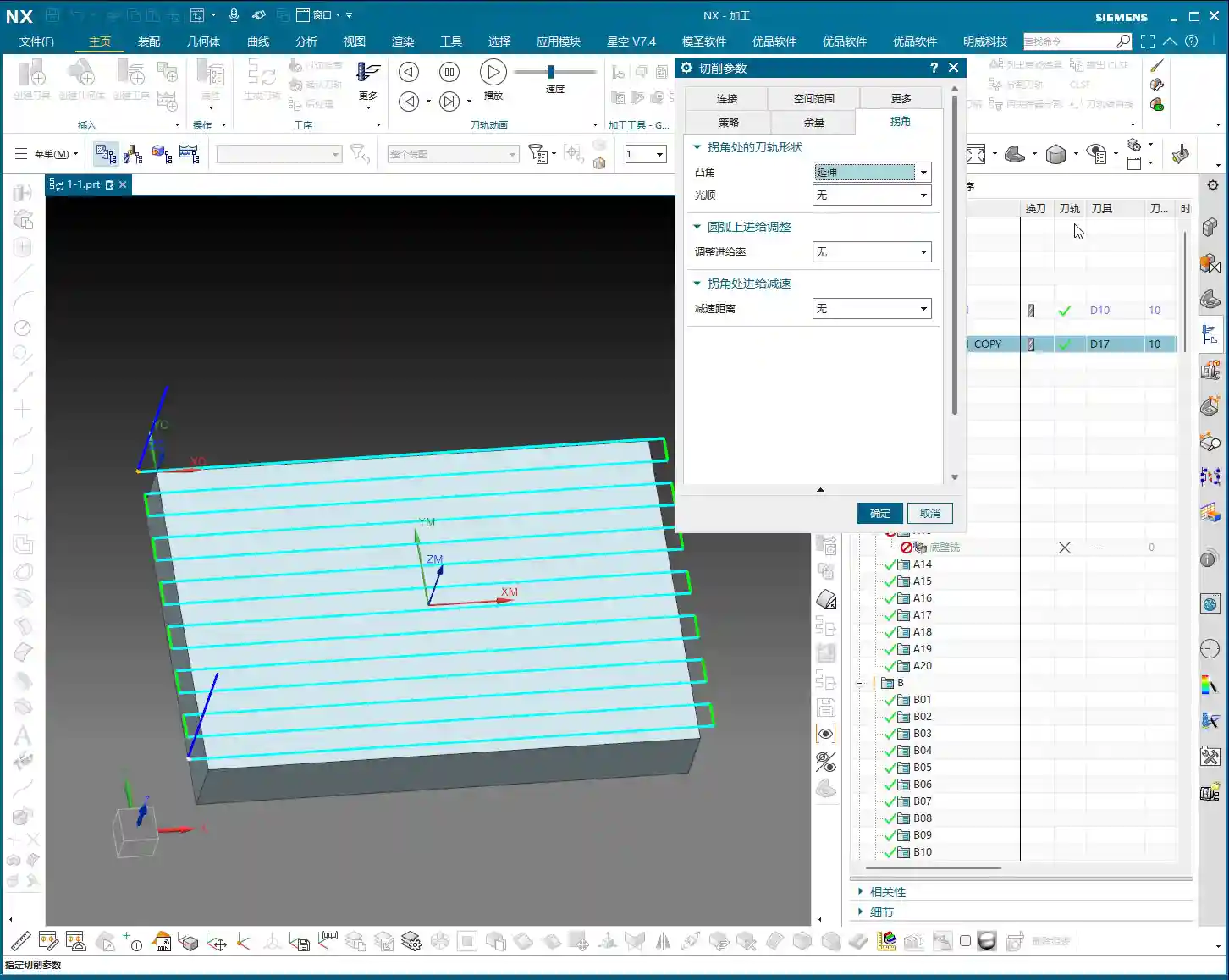
Listen up, “Extend and Trim” is a pretty common option in NX. What does it mean? Just look at this small icon, and you’ll get it.
Principle Explained
When our tool reaches an external corner of a contour, for example, a right angle, how does it move? It doesn’t just foolishly stop at that point and abruptly turn; that would lead to the tool being overloaded and chatter. NX will let the tool’s center point **extend slightly beyond**, which is what we call “extend”, and then come back to “trim” off the excess. The goal is to ensure the tool fully cuts into the corner, machining that sharp angle completely.

Practical Tips
- This option is mainly used for **external sharp corners**. It ensures that the defined contour boundary is machined cleanly and completely, without leaving any rounded corners.
- When using it, pay special attention to **tool radius compensation**. If compensation is incorrect, the tool extending too little or too much can lead to overcutting or undercutting.
- I generally use this when machining parts that require strictly maintained sharp external contours, such as square frames or right-angle steps. Remember, this is to ensure **geometrical accuracy**.

II. Roll Over
“Roll Over” is quite interesting. The difference from “Extend and Trim” becomes clear if you carefully observe the software simulation.
Principle Explained
“Roll Over” means that when the tool reaches a corner, whether external or internal, it will **automatically transition with an arc**. The tool doesn’t just go in a straight line to the sharp point but rather “rolls” over, using a fillet to complete the turn. This is like driving around a bend; no one drives straight into a corner and then makes a sudden 90-degree turn – that would surely result in a crash!

Practical Tips
- This option is used relatively little in actual machining because its behavior can be somewhat “random”, especially at **sharp corners, where it might generate an unnecessary arc**. If it creates a small arc where there should be a right angle, isn’t that just ruining the part?
- My personal experience is that if the drawing requires sharp corners, **use this option with caution**; it can easily round off intended sharp corners, especially internal corners, leading to a risk of **residual material** or **overcutting**.
- Unless you specifically require the tool to transition with an arc at all corners, I recommend using other options first, or carefully inspecting the toolpath.

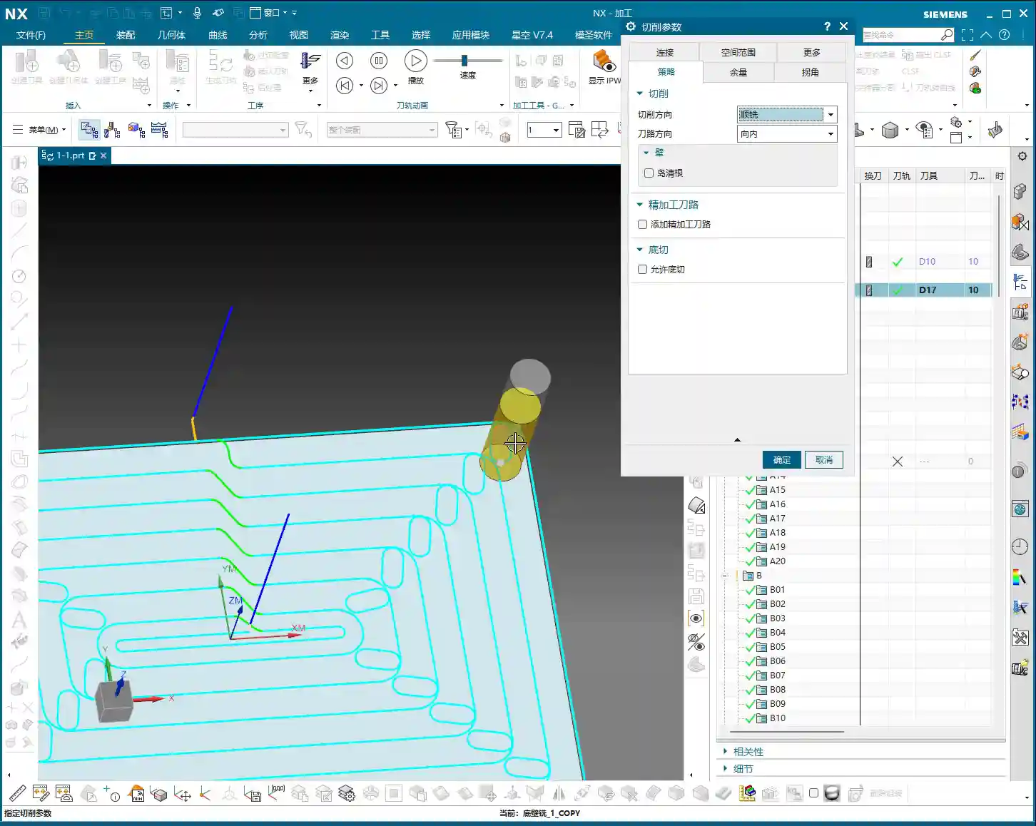
III. Smooth
This “Smooth” function is really useful! Its purpose is to soften the toolpath at corners, avoiding sudden stops and abrupt turns, which benefits both the part’s surface finish and the machine’s lifespan.

Principle Explained
The core of the “Smooth” function is to **insert an arc transition at corners**. When the tool follows the contour to a corner, it generates a small arc there instead of making a sharp 90-degree turn. This arc transition effectively prevents impacts and vibrations caused by sudden changes in the tool’s cutting direction.
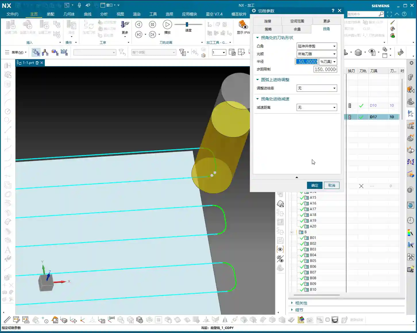
Setting the Smooth Radius
The most crucial setting here is the **Smooth Radius**. It determines the size of the corner arc.

- Percentage (%): The default is usually 5%. This percentage is relative to your current **tool diameter**. For example, if you use a D10 (10mm diameter) end mill and set it to 5%, it will generate an arc with a radius of 0.5mm at the corner. If you change it to 50%, that would be R5.
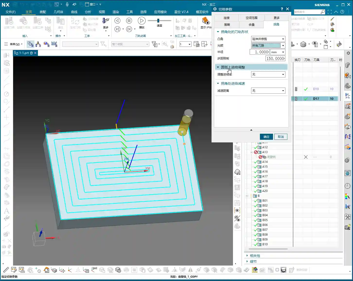
- Millimeters (mm): You can also directly input a fixed radius value, such as 1mm or 2mm. This is more straightforward; no matter what size tool you use, it will apply the fixed radius you set for the arc transition.

Differences in Internal and External Corner Handling
- Internal Corners: When the tool enters an internal corner (e.g., an internal corner of a square pocket), if “Smooth” is selected, it will generate an arc with the set radius for the transition. The advantage of this is that it **effectively reduces residual material in internal corners**, preventing the tool from “pausing” or being “overloaded” in the corner, allowing for smoother cutting, and avoiding tool chipping or part chatter marks. I typically set the smooth radius for internal corners between 0.2mm and 1.0mm, depending on part requirements and tool size.
- External Corners: Interestingly, for external corners, such as a 90-degree angle on an external contour, even if you set “Smooth”, it will usually **still follow a sharp angle**. This is because the tool follows the contour, and by going directly through the external corner, it already achieves the “sharp corner” effect. However, if you apply a large smooth radius, such as R5 or even R10, it can still be used to **optimize toolpath smoothness**, and although it doesn’t significantly affect the final part geometry, it can make the machine run more smoothly, reduce impact, and extend machine life.
Step Limit and Residual Material Cleanup
When discussing “Smooth”, the concept of “Step Limit” often comes up. Although it was a bit vague in the audio, essentially, it is closely related to **clearing residual material in corners**.
- You need to understand that if internal corners are not handled properly, the tool cannot completely remove the material in those corners, leaving **residual material**. It might look clean in the software simulation, but on the actual machine, there might be a lump of material waiting for you.
- The “Step Limit” parameter, if set correctly (e.g., 100% or even 150%), can assist the “Smooth” function by giving the tool enough “room” to clear residual material in internal corners. It forces the tool to take an extra short pass in these corners, ensuring no material remains.
- Generally, using the default value of 150% is fine and can effectively prevent residual material in internal corners. However, in special cases, such as deep cavities, you might need to increase this value for thorough cleanup.
IV. Feed Rate Adjustment on Arc and Corner Slowdown

Feed Rate Adjustment on Arc
- This option is used relatively infrequently. It means that you can independently adjust the feed rate when the tool is following an arc path.
- In actual machining, most of the time we rely on the machine’s **G61/G64 (Exact Stop/Continuous Machining)** commands or the automatically optimized feed rates from the CAM software, and rarely manually fine-tune arc feed rates. Unless there are special requirements, I generally leave it untouched.
Corner Slowdown
- This one, however, can be useful. As the name suggests, when the tool reaches a corner, it automatically reduces the feed rate.
- It is typically set as a **percentage**, for example, setting it to 50% means that at the corner, the feed rate will be reduced to 50% of the currently set feed rate.
- **Why slow down?** To reduce impact between the tool and workpiece, lower vibration, prevent premature tool wear, and improve machining quality, especially when machining hard materials or requiring a high surface finish.
- **My advice**: If you’re machining hard materials, or if the tool is prone to chipping, you might consider reducing the speed. However, generally, CAM software and the machine’s control system already do a good job, so I rarely explicitly set this parameter myself. After all, slowing down means **increased machining time and reduced efficiency**, so you need to weigh the pros and cons.
Summary: Guide to Avoiding Pitfalls
- Extend and Trim: Ensures sharp external contours are fully machined, preventing undercutting. Check toolpath for overcutting. Commonly used for external contour machining requiring precise sharp corners.
- Roll Over: Use with caution! It might generate arcs where they are not intended, leading to non-conforming parts or residual material. Avoid it unless specifically required.
- Smooth: This is a powerful tool for optimizing toolpaths and improving surface quality.
- Internal Corners: Essential! Effectively clears residual material, reduces tool impact, and improves surface finish. The radius value should be flexibly adjusted based on tool and part accuracy requirements; 0.2mm-1.0mm is commonly used.
- External Corners: Primarily used to improve machine motion smoothness; has little impact on part geometry. A larger radius can be applied.
- Step Limit: The default value of 150% is usually sufficient, working with “Smooth” to clear residual material in internal corners. If residual material remains, it can be increased.
- Corner Slowdown: Consider using for hard materials or high-precision requirements, but weigh it against efficiency. Unless necessary, the default is usually fine, or leave it to machine control.
- Core Principle: **Don’t just rely on software simulations; watch the cutting sparks!** The actual machining result is the only true test. Observe the machine’s running status, listen to the sounds, monitor cutting conditions, and flexibly adjust parameters based on experience – that’s the real key to success!
👤 About the Author:
The author is a veteran CNC machining professional with 15 years of industry experience, specializing in UG NX programming. This article is an original work representing personal practical insights.
⚠️ Copyright Notice: Unauthorized reproduction or distribution without prior communication is strictly prohibited.
Leave a Reply