📝 Key Takeaways:
Siemens NX Programming Best Practices: Connection Ribs
Hello everyone, I’m Old Wang, Master Wang. I’ve been in the machining industry for…
[VIDEO_HERE]
Hello everyone, I’m Old Wang, Master Wang. I’ve been in the machining industry for fifteen years, from the shop floor covered in swarf to sitting in front of the Siemens NX interface – I’ve seen it all. Today, let’s skip the theory and talk about the hard-earned, practical machining skills you won’t find in textbooks. Specifically, we’ll discuss creating manufacturing connection ribs for complex parts and how to program tool paths effectively to ensure your parts are produced quickly and accurately, while avoiding critical deformation.
Don’t just stare at all the fancy commands in Siemens NX. Remember, software is merely a tool; the core lies in your understanding of the part, the material, and the machine. Listen up: do this job right, and it’s craftsmanship; mess it up, and you’re just making scrap!
Step One: Part Geometry Analysis – Know Your Part, Know Your Process
When you get a part, don’t rush into modeling and programming. First, look, and look carefully! That’s the first rule from us old masters. Only by understanding your part inside and out can you master the machining process.

Identifying Surfaces and Planar Faces: Avoiding Pitfalls
I always tell my apprentices: when you get a drawing or import a model, the first thing you do is use Siemens NX’s analysis tools to thoroughly understand the part’s geometric features. Don’t just glance at it; examine every single face clearly:
- Which are planar faces? Planar face machining is simpler and more efficient, but you still need to pay attention to dimensional accuracy and surface roughness.
- Which are curved surfaces? Especially freeform surfaces—this is where your Siemens NX expertise is truly tested. Curved surface machining involves complex tool paths and is prone to high cutting forces, so you need to pay extra attention to tool selection and feed strategies. Just now, when I analyzed that part, I found one area that wasn’t purely flat; it was a curved surface. That immediately raised a red flag. A standard flat-end mill definitely won’t work there; you’ll either need to finish it with a ball end mill or figure out another way to avoid it.
Only by understanding these thoroughly will you know where the machining challenges lie and where problems are likely to occur. It’s like going into battle: you need to know where the enemy’s strongpoints are, not just blindly charge in.
Considering Radii and Slopes: Key Factors for Tool Selection
Small radii and slopes are critical information that determines which tool you use and how you machine.
- I just measured, and the part has many radii: R4, R2, and even R5.5. This tells us that we might use a larger tool for roughing, but for finishing side walls and Corner Cleanup, we’ll need to switch to smaller tools. For example, for an R4 fillet, you’ll need at least an R2 ball end mill or flat-end mill for Corner Cleanup; otherwise, you won’t clear the corner properly, and all your effort will be wasted.
- Next, consider the slopes. Some faces look flat but actually have a slight incline – that’s a slope. If the slope changes significantly and you use a flat-end mill, obvious step marks will appear, resulting in poor surface quality. In such cases, you need to consider using a ball end mill or bull nose end mill, or even engaging 5-axis simultaneous machining, to ensure a smooth finish.
All of this can be identified using Siemens NX’s “Analysis Tools.” Don’t be lazy; a few extra clicks of the mouse now will save you a lot of hassle compared to re-working a part after machine issues arise. That’s real money down the drain!
Step Two: Constructing Manufacturing Connection Ribs – Virtual Support, Real Stability

Some parts are thin, weak, and complex, especially thin-walled components for aerospace applications, which are highly susceptible to deformation and chatter during machining. This is where manufacturing connection ribs come in extremely handy. They are not part of the final component but serve as temporary support during the machining process, and are cut off once machining is complete.
“Enveloping Body” and Stock Allowance Setting: Ample Material, Sufficient Clearance
First, in Siemens NX, we need to create an “enveloping body” for the part, which is essentially our raw material blank or machining boundary. This enveloping body must not only enclose the part itself but also provide sufficient space for our connection ribs. I typically offset additional allowance (extra material) on all sides (top, bottom, left, right) of the enveloping body. For instance, I might start with 20mm and then adjust it to 15mm or even 14mm based on actual requirements. This allowance is crucial; it directly impacts the thickness of your connection ribs and the clearance needed when you eventually cut them off. You can’t make the ribs too thin, or they won’t provide adequate support, nor too thick, as that makes cutting them off a hassle.
Furthermore, if you want to leave some allowance when machining the connection ribs, for example, using a Ø25 tool for cutting them off, then our enveloping body at the connection rib locations must extend an additional 12.5mm (tool radius) outwards. This ensures there’s enough material to cut.
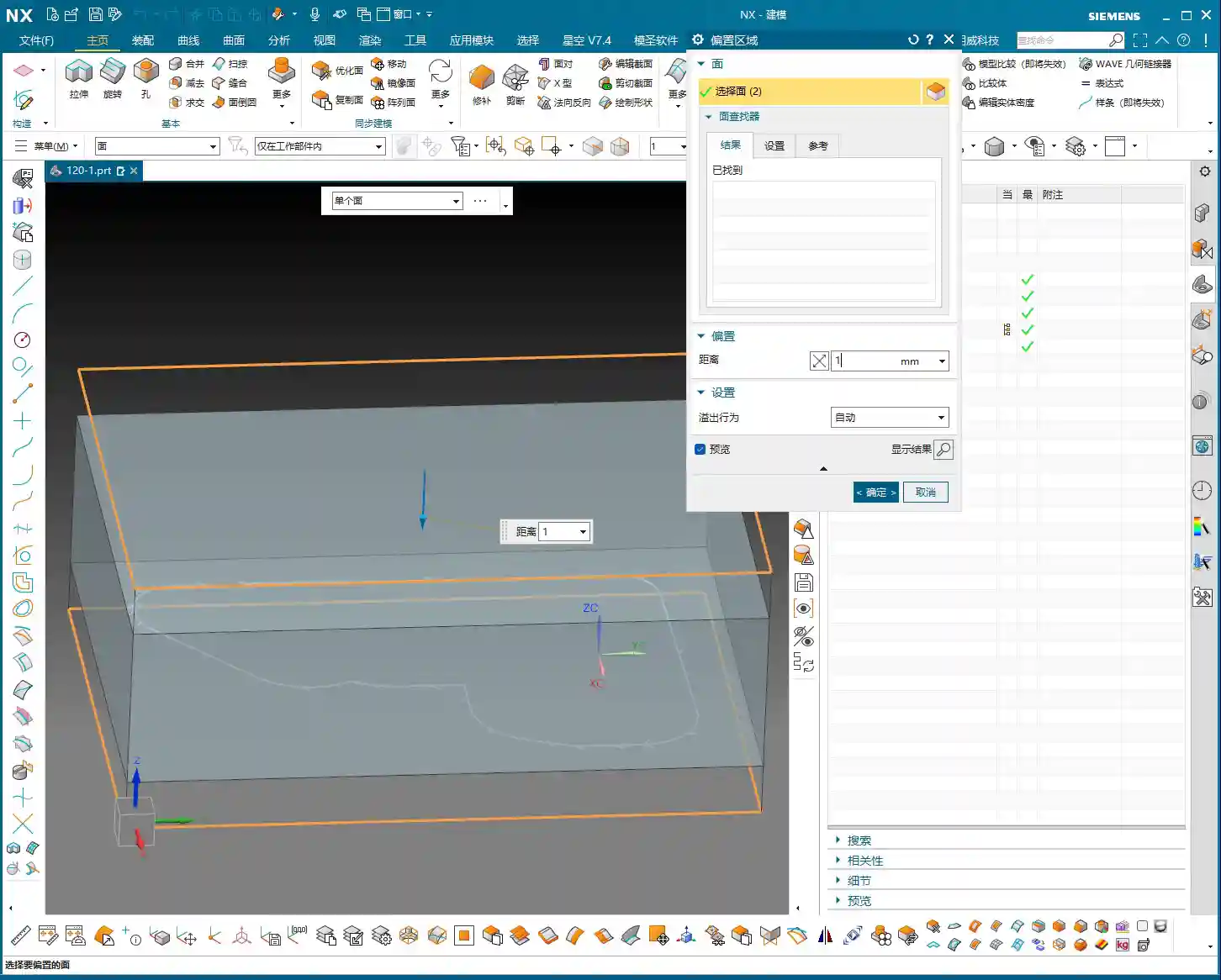
Extruding and Adjusting Critical Faces: Meticulous Geometric Refinement
Building connection ribs isn’t just about drawing a few lines. We need to precisely extrude and adjust the relevant faces of the part to provide a stable “foundation” for the connection ribs. For instance, I just noticed some faces were excessive or had small corners. To ensure the connection ribs connect and support better, I need to use the “Extrude” command to extrude these faces outwards by -1mm, or use “Replace Face” to replace irregular areas, thereby ensuring the integrity and smoothness of the geometric structure. This process is like sculpting, meticulously refining bit by bit. There can be no burrs or breaks, otherwise, the resulting connection ribs will be like a shoddy construction.

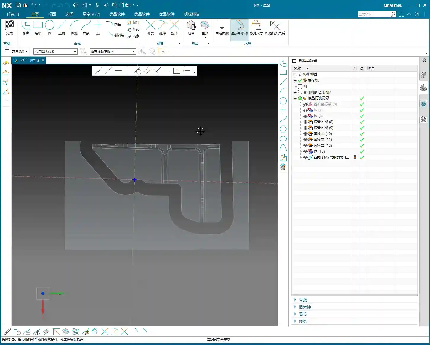
Sketching and Extruding Connection Ribs: The “Lifeline” for Stable Machining
Next comes the main event: drawing the connection ribs. This requires a strategic approach:
- Placement: Connection ribs should be positioned at the part’s weakest points, where deformation is most likely, and at load-bearing areas. Generally, this means along the edges and thin-walled regions of the part.
- Quantity and Density: Determine this based on the part’s rigidity and the magnitude of machining forces. Too few ribs won’t provide enough support; too many will increase subsequent cutting time and cost. You need to find a balance.
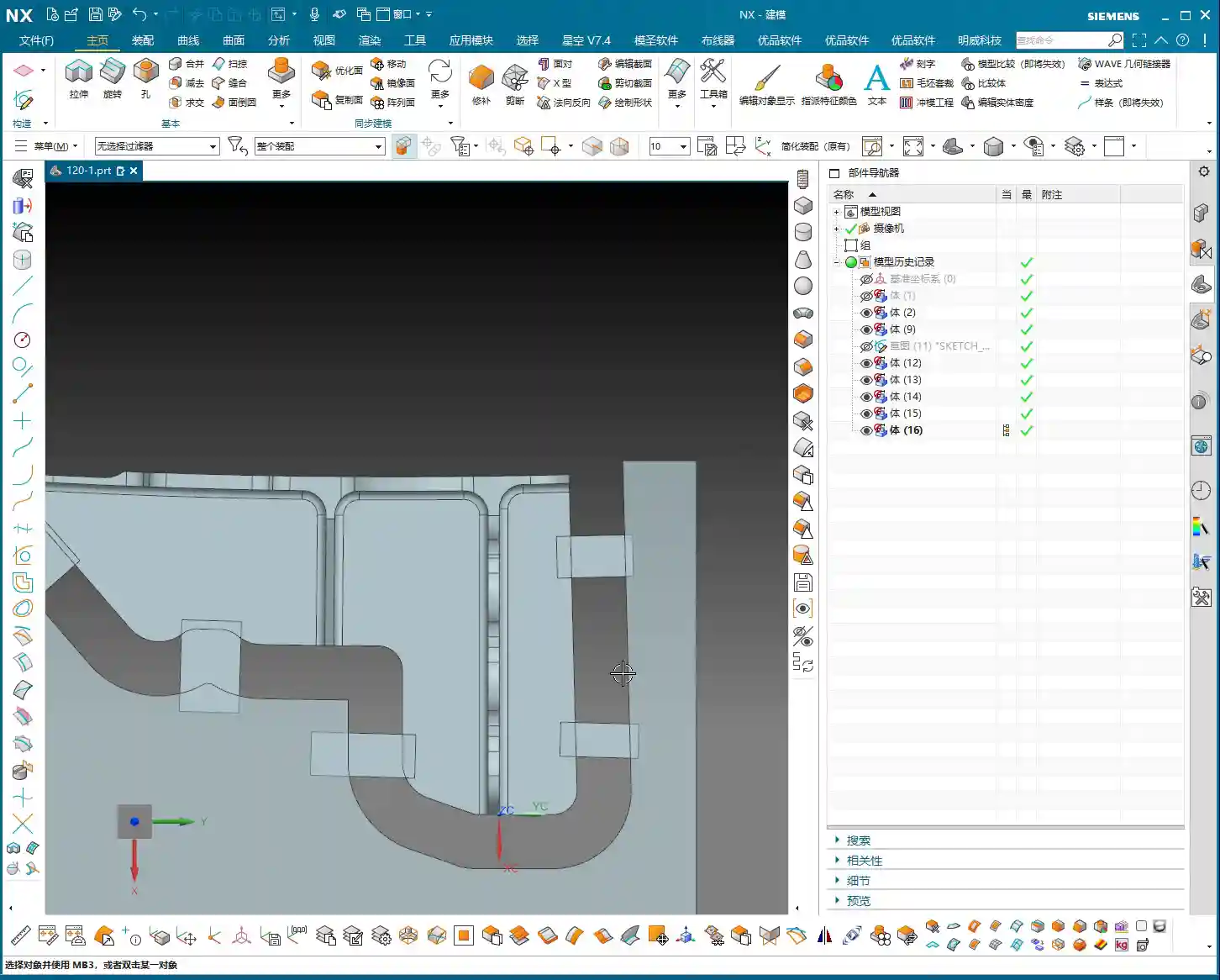
- Sketching: Draw the connection rib sketches on the relevant faces of the part. Lines, arcs, or splines are all acceptable, but they should be as simple as possible to facilitate subsequent machining and cutting off. Just now, I sketched a few auxiliary lines and then used the “Extrude” command directly to extrude these sketches into solid bodies. I usually set the thickness to 5mm initially, which can be adjusted later.
These connection ribs are the “lifeline” for the part during machining on the machine tool. They determine whether your part is machined stably and successfully, or ends up as scrap mid-process.
“Replace Face” for Uniform Height: Ensuring Support Stability
This is a highly practical “pitfall avoidance” technique! Because various faces on the main part might have different heights, if you simply extrude the connection ribs, they might not end up on the same plane, leading to unstable support or even gaps. I just noticed that many connection ribs had varying heights. In such cases, you need to use the “Replace Face” command to uniformly replace the top faces of all connection ribs to a single reference plane on the part (e.g., the highest point or a datum plane). This ensures that the tops of all connection ribs are at the same height, guaranteeing overall support stability and facilitating subsequent clamping with straps, thereby reducing chatter. Don’t underestimate this step; it’s critical for ensuring your part remains absolutely stable during machining!
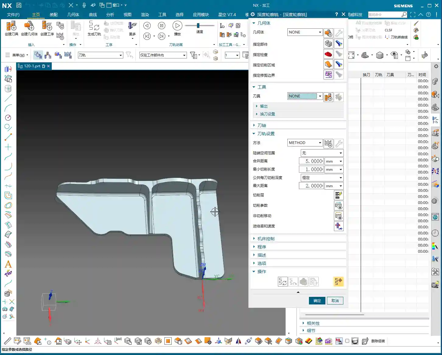
Step Three: Tool Selection and Tool Path Optimization – The Art of Balancing Efficiency and Precision

Once the connection ribs are built and the raw material blank is defined, it’s time for programming. This is my forte, and with Siemens NX, it’s all about “finesse.”
Deriving Tools from Radii: The Right Tool for Maximum Effectiveness
Selecting the wrong tool is simply burning money. The radii we just analyzed now come into play. Determine the tool type and size based on the smallest radius and machining requirements.
- For example, for side wall Corner Cleanup with a minimum radius of R2, you’ll need at least a Ø4 flat-end mill or an R2 ball nose end mill. I just decided to use a Ø10 or Ø12 flat-end mill to machine the side walls.
- For the final cutting off of connection ribs, to ensure efficiency and surface quality, a slightly larger tool is typically used. I selected a Ø24 or Ø25 flat-end mill, leaving 12mm or 12.5mm of cutting allowance. The principle for tool selection is: while meeting dimensional and surface finish requirements, opt for the largest possible tool to reduce tool deflection and increase machining efficiency.
Don’t just rely on software recommendations; you must make comprehensive judgments based on your machine rigidity, material hardness, and tool material. Otherwise, you’ll break tools and scrap parts, and it’ll be too late for regrets.
Optimizing Cutting Layers and “Air Cuts”: Ensuring Every Cut is Productive
This is paramount for efficiency! Tool paths automatically generated by Siemens NX often contain numerous redundant cutting layers and air cuts.
- Managing Cutting Layers: I just did this – deleted all the default cutting layers generated by the system, keeping only the most effective ones, or manually adjusting them based on actual conditions. Don’t foolishly let the software calculate every single layer; many are just idle moves, wasting time, wearing out the spindle, and increasing program size. Only keeping layers with actual material removal is the optimal approach.
- Reducing Air Cuts: When the tool moves in the air without cutting, that’s an “air cut.” More air cuts mean longer machining times. In Siemens NX, you can minimize air cuts by adjusting parameters such as lead-in/lead-out, connection methods, and non-cutting move strategies. Especially for complex surfaces and cavity machining, optimizing air cuts can save a significant amount of time. The version of Siemens NX I’m currently using, with high-efficiency tool paths like Adaptive Milling, can greatly reduce air cuts and ensure more stable cutting.
Remember, time is money, especially in mass production. Every minute saved directly contributes to increased profit. This is a key “selling point” we can emphasize when promoting industrial products online: high-efficiency, low-cost precision machining – that’s what customers love to hear!
Siemens NX Programming Best Practices: The Clever Use of Post Processors and Macros
Siemens NX programming isn’t just about clicking a mouse. Advanced users also need to be proficient with Post Processors and Macros.
- Post Processor Modification: Your machine tool might have specific commands or cycles. In such cases, you’ll need to modify the Post Processor so that the G-code generated by Siemens NX can perfectly adapt to your machine. This requires some understanding of machine parameters and control system codes like Fanuc and Siemens. Don’t be intimidated; master this, and your Siemens NX programs will run flawlessly on any machine. I even fine-tune Post Processors based on different machine characteristics to output more efficient G-code, reducing unnecessary tool changes or retract moves.
- Utilizing Macros: For highly repetitive operations, such as standard drilling cycles or engraving, you can write macros to complete them with a single click, significantly boosting efficiency. It’s like installing an “accelerator” for Siemens NX, turning your experience into reusable code.
When you master all of these, you won’t just be a Siemens NX operator; you’ll be a true Siemens NX expert, an “old master” of the industrial world. The reason our high-precision parts are promoted so successfully online, with keywords (such as “high-precision 5-axis machining” or “custom complex structural components“) consistently ranking on the front page, is precisely due to this solid process foundation and efficient programming capability, which ensures product quality and on-time delivery. Customers look for tangible benefits, not flashy advertising.
Summary: Pitfall Avoidance Guide
Alright, everything I’ve discussed today has been learned through hard-won lessons. Finally, let me summarize a few key points for you. Remember, these are Master Wang’s Ironclad Rules for avoiding pitfalls:
- Never skip geometric analysis! Especially for curved surfaces, radii, and slopes – these are the soul of tool selection and tool path strategy. Don’t rush into it; first, think the job through carefully in your head.
- Connection ribs are not to be sketched haphazardly! You must ensure their structural rigidity, proper placement, and uniform height (frequently use “Replace Face”). Otherwise, if chatter or deformation occurs during machining, your part will be scrapped.
- Tool selection should be “clever,” not just “expensive”! Size, type, and material must be determined based on part characteristics and machine performance. Choose the wrong tool, and you’ll either break the tool or chip its cutting edge.
- Tool path optimization saves money! Especially with cutting layers and air cuts – reduce them whenever possible. Don’t let your machine run idle; that’s literally burning your money.
- Don’t just rely on software simulation; observe the cutting sparks! No matter how perfect the software simulation, it cannot replace the experience of actual machine operation. Cutting sounds, spark color, and chip evacuation conditions can all tell you if there’s a problem with the machining process.
- Pay close attention to clamping and heat treatment! Even the best programming is useless without secure clamping and appropriate post-processing (e.g., heat treatment to prevent deformation). Every link in the entire machining chain must be robust.
Alright, that’s it for today’s lesson. Practice more, think more, and summarize more, and you too can become the “Master Wang” of your shop floor!
👤 About the Author:
The author is a veteran CNC machining professional with 15 years of industry experience, specializing in UG NX programming. This article is an original work representing personal practical insights.
⚠️ Copyright Notice: Unauthorized reproduction or distribution without prior communication is strictly prohibited.
Leave a Reply