📝 Key Takeaways: Master Wang personally guides you through practical techniques for Siemens NX cavity milling rest roughing, from correctly selecting commands and setting up stock, to a core explanation of “In-Process Workpiece” and “Reference Tool.” He reveals the “Minimum Residual Material” parameter, helping you optimize toolpaths, efficiently perform corner cleanup, thoroughly eliminate unmachined areas, and achieve high-quality part machining.
Hello everyone, I’m Master Wang. Last time, we pretty much covered roughing; today, we’ll continue with rest roughing. Don’t underestimate it – when used well, this technique can save you a lot of finishing time and effectively improve the part’s surface quality.
Rest Roughing Operation: Siemens NX Command Selection and Initial Setup
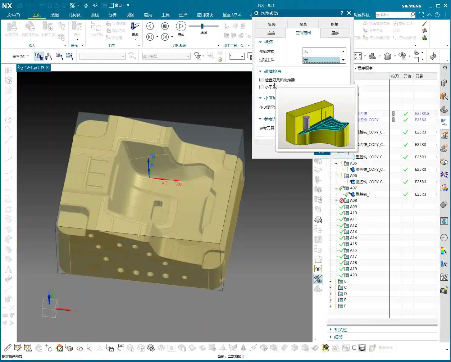
Listen closely: for rest roughing in NX, we’ll directly choose the “Cavity Milling Rest Roughing” command. Simply put, it’s a branch of cavity milling, but NX engineers have pre-set some parameters for you, making it more suitable for corner cleanup and processing material left from the previous roughing pass. If you were to use it for initial roughing, it’s not impossible, but you’d have to change a bunch of parameters—why create trouble for yourself? It’s time-consuming, laborious, and not worth it!
- Operation Entry: Directly select “Cavity Milling Rest Roughing”.
- Stock and Part: This section is the same as the initial roughing; just click OK, no need to change. The system will default to your previous settings.
- Tool Selection: Rest roughing, as the name suggests, is used to clear corners unreachable by the large tool during the previous roughing pass. Therefore, you need to select a tool with a smaller diameter, typically a ball end mill or bull nose end mill, and a smaller corner radius (R value) than the roughing tool. For example, if you used a D25R3 for roughing, you might consider a D12R1 for rest roughing.
- Cutting Parameters:
- Cut Pattern: Generally, use “Contour Part”; this is the most common method.
- Depth of Cut (DOC): This parameter is crucial. We typically set it to around 0.5mm, depending on material hardness and tool strength. Don’t make it too large; corner cleanup is not about aggressive roughing, it needs to be stable.
- Cutting Depth: If there are no special requirements, such as not wanting to mill a deep hole all the way through, or if a specific area has depth restrictions, then usually keep the default. Don’t change it arbitrarily, or the toolpath will be messy.

Core Secrets: Correct Usage of In-Process Workpiece and Reference Tool
Alright, now let’s talk about the two most critical points for rest roughing, where many novices often stumble. Listen up!

“In-Process Workpiece”: The “Eyes” of Rest Roughing
Why is it that even though you’ve set up rest roughing, the toolpath isn’t calculated? Or it calculates a bunch of redundant toolpaths? The problem lies here:
- Core Setting: In the rest roughing parameter settings, find the “Geometry” tab, and set “In-Process Workpiece” to “5”! Remember, it’s the number “5”!
- Principle: Setting it to “5” tells the system: “Hey, I’ve already machined this with a previous tool; now, show me where the unmachined residual material is, and only machine those areas!” If you don’t set it to “5”, the system won’t know what you did before; it will treat it as initial roughing, and naturally, it will get confused, either failing to calculate a toolpath or generating a bunch of useless ones.
“Reference Tool”: The “Compass” of Rest Roughing
Just setting “In-Process Workpiece” isn’t enough; you also need to point it in the right direction.
- Function: The “Reference Tool” tells the system which tool was used previously and its size. Based on the shape and size of this reference tool, combined with the “In-Process Workpiece” instruction, the system can accurately calculate where residual material remains and needs to be cleared by the current smaller tool.
- Selection Technique:
- First Rest Roughing Pass: Select the large tool you used for the previous roughing pass. For instance, if you used a D25R3 for roughing, then for the first rest roughing pass, select D25R3 as the reference tool.
- Multiple Rest Roughing Passes: If you need to perform multi-level rest roughing (e.g., D25R3 → D12R1 → D8R1), then each level of rest roughing must reference the machining tool from its preceding level. For example, when using a D8R1 for rest roughing, the reference tool should be D12R1.
- Create New Tool: If the corresponding reference tool isn’t in your library, simply create a new one and ensure the parameters are set correctly. The important thing is that the parameters accurately reflect the dimensions of the previous tool.
- Engagement Strategy: For parameters like “Plunge Engage”, I typically set it to 1mm to ensure stable engagement and prevent excessive cutting impact.

Striving for Excellence: Toolpath Optimization and Practical Experience
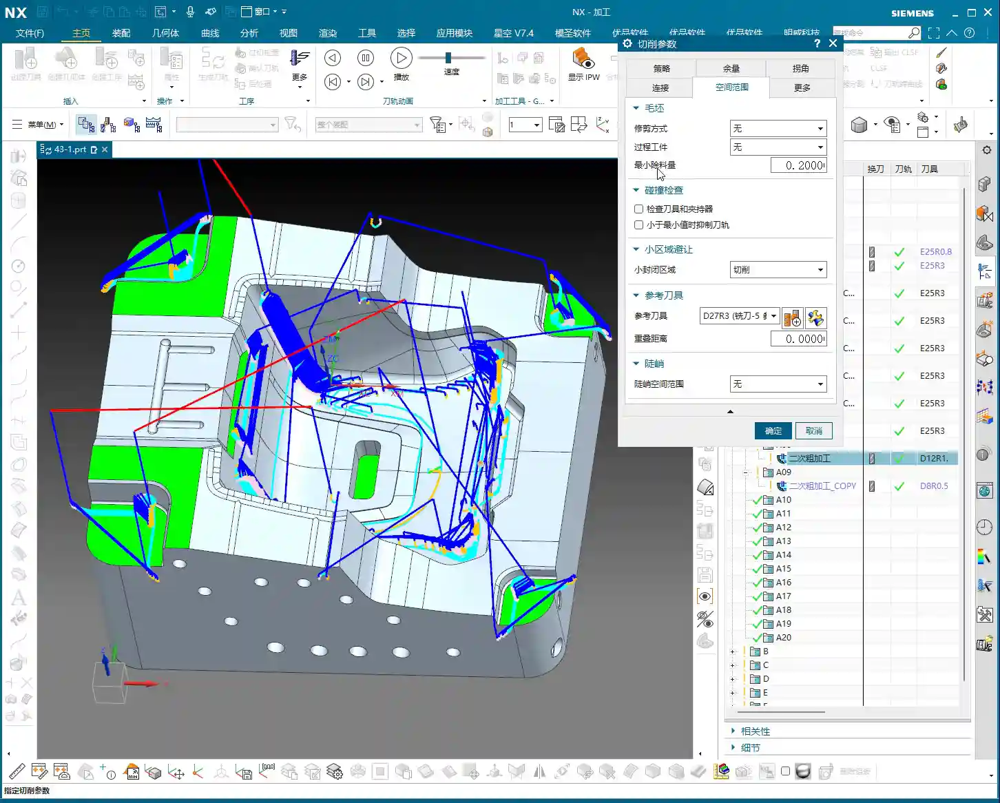
The Secret of “Minimum Residual Material”
This parameter is also a critical one; often, an unclean toolpath or mysterious small paths are related to it.
- Definition: “Minimum Residual Material” means that if the thickness of the material remaining in a certain area after the previous machining is smaller than the value you set, then the current tool will not machine it.
- Application: For example, if you set it to 0.2mm, then areas with only 0.1mm or less material remaining will be considered by the system as “not necessary to cut, leave it for finishing or the next smaller tool,” and thus ignored.
- Master Wang’s Experience:
- This value should typically be set to half of the previous tool’s “Depth of Cut” (DOC), or slightly less than the corner radius of your current machining tool.
- For example, if the previous tool’s DOC was 1mm, then this value can be set to 0.5mm, or even slightly smaller like 0.4mm or 0.3mm.
- Setting this value appropriately can effectively prevent the tool from cutting tiny scraps, which wastes time, causes tool wear, and reduces efficiency.

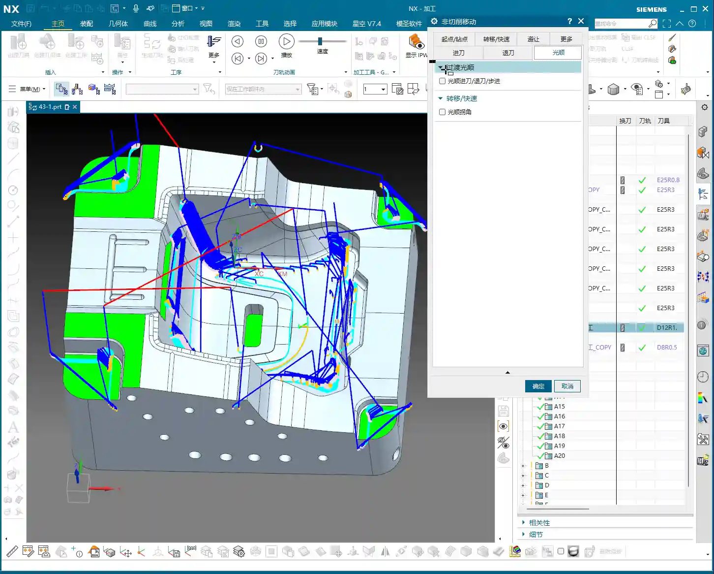
“Trim Boundaries”: A Great Helper for Streamlining Toolpaths
Rest roughing toolpaths can sometimes be a bit redundant, especially in less critical areas.
- Function: Through “Trim Boundaries”, you can manually specify a point or area to make the tool avoid these places and stop generating toolpaths there.
- Purpose: This helps you optimize the toolpath, making it more streamlined and efficient. Sometimes, the residual material in certain areas doesn’t need to be cleared again, or you want to handle it in another way, so you can trim it.
Multi-Level Rest Roughing: Layer by Layer, Step by Step
For complex cavities or high-precision requirements, a single rest roughing pass is often insufficient. We can proceed layer by layer, like peeling an onion, to go deeper.
- Approach: You can duplicate the current rest roughing operation, then switch to a smaller tool, and simultaneously update the “Reference Tool” to the machining tool from the previous level.
- Example:
- D25R3 roughing.
- D12R1 rest roughing, referencing D25R3.
- D8R1 rest roughing, referencing D12R1.
This is called a “Corner Cleanup Sequence”, which ensures every corner is thoroughly cleared, laying a solid foundation for the final finishing pass.
Allowance Control: Making Toolpaths Smoother
Here’s another small detail that can make your rest roughing toolpaths “smarter.”
- Master Wang’s Experience: During rest roughing, the allowance left should ideally be slightly smaller than during initial roughing. For example, if roughing leaves 0.35mm, rest roughing can leave 0.25mm or 0.2mm.
- Benefit: Doing so prevents the tool from repeatedly cutting areas that have already been cleared, making the toolpath smoother, reducing air cutting, and improving efficiency.
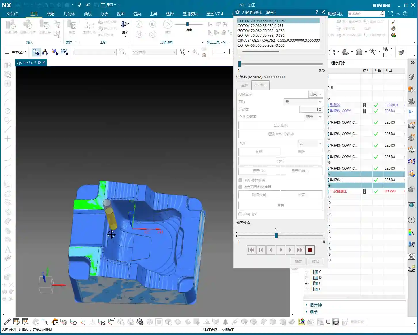
Machining Simulation and Verification
NX’s simulation function is very powerful, but don’t just watch it run through once and call it a day.
- Key Point: During simulation, pay special attention to the tool’s movement in complex areas like corners and deep cavities. Compare before and after rest roughing to see if the residual material in these areas has been effectively removed.
- Details: Some subtle residual material might only be discovered by zooming in and carefully observing the simulation. Don’t rely solely on software simulation; during actual machining, you also need to observe cutting sparks and listen to cutting sounds—those are the most authentic feedback.
Master Wang’s Summary: Pitfall Avoidance Guide
In our line of work, theoretical knowledge alone isn’t enough; practical experience is key. For today’s rest roughing, just remember these points to ensure you take the shortest path to success:
- In-Process Workpiece: Always “5”! This is the soul of rest roughing; without it, everything else is moot.
- Reference Tool: Absolutely select the tool actually used in the preceding machining level. This is the eyes of rest roughing, telling the system where material still remains.
- Minimum Residual Material: Set it appropriately, usually smaller than the previous tool’s depth of cut and the current tool’s radius, to avoid meaningless small cuts, protect the tool, and improve efficiency.
- Decreasing Allowance: The allowance for rest roughing should be slightly smaller than the initial roughing pass, making the toolpath smoother and avoiding redundant machining.
- Toolpath Optimization: Use “Trim Boundaries” to remove redundant toolpaths, making the program more streamlined.
- Multi-Level Corner Cleanup: For complex parts or those requiring high precision, consider using multi-level rest roughing, progressing with tools of different diameters layer by layer to thoroughly remove all residual material.
These are experiences I’ve accumulated over 15 years of hard work on the front lines; you might not find them in textbooks, but they’ll definitely be useful to you! Go back, digest this, practice more on the machine, and if you don’t understand, come ask me again.
👤 About the Author:
The author is a veteran CNC machining professional with 15 years of industry experience, specializing in UG NX programming. This article is an original work representing personal practical insights.
⚠️ Copyright Notice: Unauthorized reproduction or distribution without prior communication is strictly prohibited.
Leave a Reply