📝 Key Takeaways:
Deep Contour Milling: Practical Insights into Cutting Layers and Boundary Extension
Alright, listen up, young…
Alright, listen up, young machinists! Today, Master Wang is going to share some critical, practical knowledge about deep contour milling—the kind of stuff they don’t teach you in textbooks, but that you absolutely need on the shop floor. Specifically, we’ll talk about cutting layer control and the boundary extension function. Use them wisely, and you’ll boost efficiency; mess them up, and you’ll be scrapping parts, wasting time, and burning through tools. Don’t just rely on software simulations; look at the cutting sparks and the chip color—that’s where the real skill lies!
I. Cutting Layer Control in Deep Contour Milling
Deep contour milling, as the name suggests, is primarily used for finishing parts with sloped surfaces, deep cavities, and internal radii. Its main characteristic is the ability to follow the part geometry layer by layer. However, *how* these layers are machined is where the critical knowledge comes in.
1. Understanding “Stepdown”: The Key to Machining Efficiency and Surface Quality
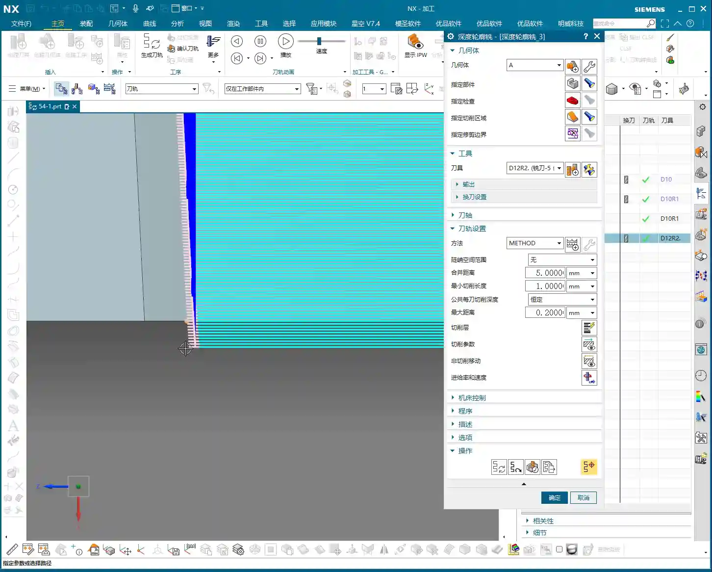
Look, once we’ve selected “Deep Contour Milling” and specified the tool, the next step is to set the Stepdown (Depth of Cut per pass or Step Length). This isn’t just a number you can randomly input. For example, if you choose 0.2mm, the tool will machine down in 0.2mm increments. But here’s a pitfall: when machining slopes, if your Stepdown is too large, the surface finish will definitely suffer. You’ll get noticeable tool marks, and it could even lead to excessive Depth of Cut (DOC).
- Small Stepdown: Better surface quality, but longer machining time. Tool wear is also more uniform.
- Large Stepdown: Higher efficiency, but poorer surface roughness, especially on sloped surfaces, where it can easily create noticeable step lines, uneven tool loads, and even tool chipping.
My usual practice is to use a larger Stepdown for roughing, leave some stock, and then switch to a smaller Stepdown for the finishing pass. It’s the same principle as sanding a part by hand.
2. Finishing Pass Depth and Fillet Corner Cleanup Issues

Listen up, this is a critical point! When you’re deep contour milling to the bottom of a feature, especially if there’s a fillet (radius) at the workpiece’s base, have you ever noticed that even when the tool clearly reaches the bottom, that fillet always seems to be unfinished? Or perhaps the bottom looks flat, but the dimension is slightly off?
The problem lies here: the software typically defaults to letting the tool’s bottom just touch the selected bottom surface. However, the cutting edge of the tool has a radius; it cannot perfectly conform to that theoretical “point.” This is especially true for ball nose end mills or bull nose end mills, which have a radial bottom edge. If the tool’s bottom radius is the same size as the workpiece’s bottom fillet, the tool will stop as soon as its center reaches the endpoint. Naturally, the fillet at the bottom won’t be fully cleaned up.
We need to make the tool go a bit deeper to thoroughly clean up that fillet. How do we do this?
- Open the Levels settings.
- Find the Bottom parameter. This typically displays the Z-coordinate of the workpiece bottom.
- Critical Step: After this value, manually add a negative value, for example, add -0.2 (or +0.2, depending on your NX version and preference, meaning to make the tool go an additional 0.2mm). For instance, if the bottom is -100mm, you’d change it to -100.2mm.
- NX’s Quirks: Sometimes, after you change a value, the interface might not react immediately, or it might still show the old value. Don’t panic! After entering the value in the box, click on another empty area or simply click “OK”, and it will take effect. This is a common quirk of NX; you’ll get used to it.
This slight over-cut is essential to ensure that the tool’s effective cutting edge thoroughly machines the workpiece’s fillet. When manufacturing precision parts with ±0.005mm (approx. 0.0002 inch) accuracy requirements, these meticulous details are what make the difference.
II. Toolpath Strategies: Climb, Conventional, and Mixed Milling
Now that we’ve covered cutting layers, let’s talk about toolpath selection. In deep contour milling, there are several commonly used cutting strategies: climb milling, conventional milling, and mixed milling.
1. Climb Milling
Listen up, Climb Milling is when the tool’s rotation direction is the same as the feed direction. The tool begins cutting at the maximum chip thickness, and the cutting forces push the workpiece down into the workholding, resulting in a relatively stable cut.
- Advantages: Good surface finish, relatively longer tool life, less prone to burr formation.
- Disadvantages: Requires high machine rigidity and is particularly sensitive to backlash in the ball screws. If the machine has significant backlash, a ‘creeping’ effect can occur, impacting accuracy.
- Typical Toolpath: Cut, retract, plunge, cut again. As demonstrated in the video, the tool repeatedly lifts and plunges. While not the most efficient, it’s often used when surface quality is a critical requirement.

2. Conventional Milling
Conventional Milling is when the tool’s rotation direction is opposite to the feed direction. The tool begins cutting at the minimum chip thickness, and the cutting forces tend to lift the workpiece.
- Advantages: Relatively lower machine precision requirements, less prone to ‘creeping’ effects.
- Disadvantages: Surface quality is typically inferior to climb milling, faster tool wear, and prone to burr formation.
- Use Cases: Rarely used alone for finishing passes. Generally considered for roughing when chip evacuation is critical or when machining specific materials.
3. Mixed Milling (Zig-zag)
Mixed Milling, simply put, is “go forward, then come back, go forward, then come back.” It combines the characteristics of both climb and conventional milling; one direction is climb milling, and the reverse direction is conventional milling. If you see a toolpath in the video that doesn’t retract but moves back and forth directly, that’s mixed milling.
- Advantages: Highest efficiency, shortest toolpath, eliminates numerous tool retracts.
- Disadvantages: Inherits the drawbacks of both climb and conventional milling. When machining in the conventional milling direction, surface quality and tool wear may be affected.
- Use Cases: A preferred choice, especially when surface quality requirements are not absolute top-tier, but high efficiency is crucial. For instance, mixed milling is an excellent option for most roughing and semi-finishing operations. Think about it: fewer retracts mean fewer air cuts, which saves time, and time is money!
Typically, climb milling is frequently used for finishing vertical walls, and mixed milling is also common, but conventional milling is relatively rare. Why? Because finishing walls demands a good surface finish, where climb milling excels. Mixed milling offers high efficiency and a good balance. You need to select your strategy based on the workpiece material, accuracy requirements, surface finish requirements, and machine condition. There’s no one-size-fits-all solution, only the most suitable approach.
III. Boundary Extension: Optimizing Toolpaths and Preventing Residual Material

Now let’s discuss a very practical function: Extend along Boundary. This feature sounds simple, but when used correctly, it can significantly improve your machining quality and efficiency, preventing many costly rework issues.
1. Why is Boundary Extension Necessary?
Often, when machining a pocket or a contour, the tool’s center follows the boundary. This means that the tool’s radius portion will leave a small amount of residual material on the workpiece edge. This is especially true in corners or along pocket edges, as the tool cannot achieve a perfect 90-degree cut, always leaving a slight amount of material. Over time, you’ll find that the edges aren’t sharp enough, or dimensions have slight deviations.
Therefore, by making the tool extend slightly beyond the boundary, you can completely remove this residual material, ensuring clean edges and precise dimensions. This is the core purpose of boundary extension.
Consider this: an aerospace component or a precision mold with even a tiny bit of residual material on its edges—can you still call that “precision”? This directly impacts product assembly and performance, and could even lead to an entire batch being scrapped, resulting in significant losses.
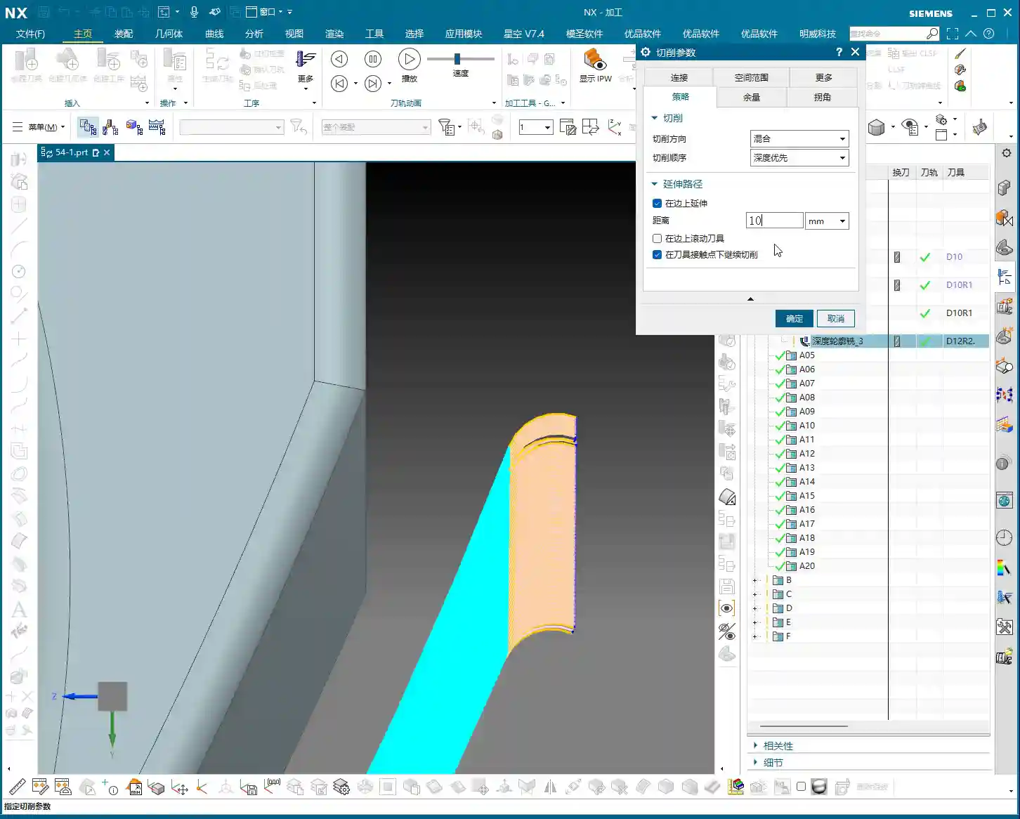
2. NX Operation: Extension Parameter Settings and Practical Effects
This function in NX is typically found in options related to Non-Cutting Moves or Cutting Parameters. You can set a distance, such as 10mm, in the Extend section. Once this parameter is set, the toolpath will extend outwards from the boundary line by that specified distance.
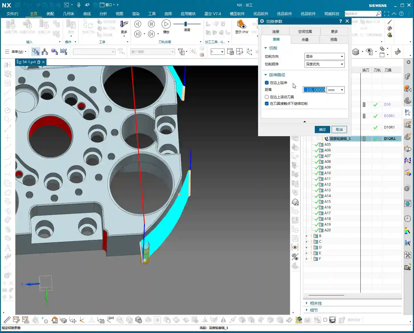
But! Here’s another pitfall! If you’re using the default “Automatic” setting, the tool will extend along all boundaries, including top, bottom, left, and right. This can lead to problems.
- Unnecessary Extension: Some workpieces may not require extension at the top and bottom. Extending there could even cause collisions with fixtures or interfere with other machining operations.
- Misconception: Many people assume “Extend along Boundary” only affects horizontal directions, but NX’s automatic mode is comprehensive.

3. Combining with Cutting Layers: Precise Control of Extension Range
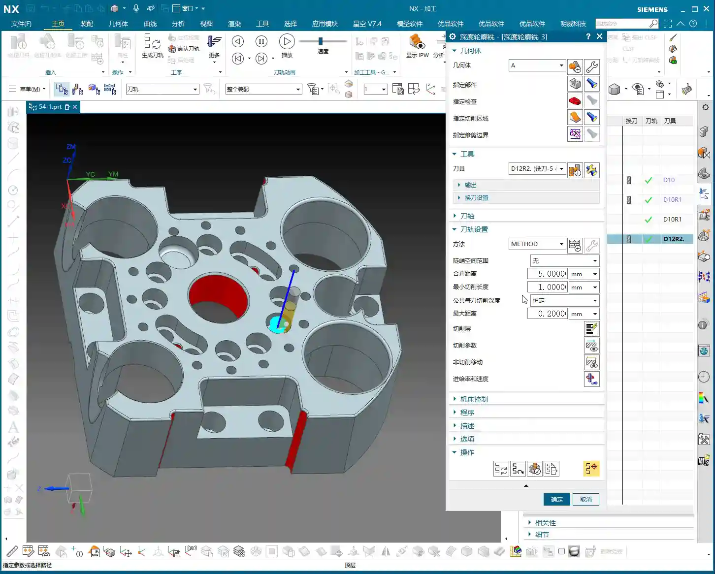
This is the real “master technique” Master Wang is teaching you! When you only want the tool to extend sideways, and not upwards or downwards, you can’t rely solely on the “Extend along Boundary” parameter.
You need to use the Levels settings, specifically the “Top” and “Bottom” options. Once you have explicitly selected the top and bottom surfaces to be machined here, then combine it with the “Extend along Boundary” function, and you’ll see the magic happen.
Because you have already constrained the tool’s machining range in the Z-axis through “Top” and “Bottom,” the “Extend along Boundary” function will only extend along the edges of these defined surfaces. It will no longer blindly extend upwards or downwards.
This is the combined use of “Levels” and “Extend along Boundary.” Listen closely, this isn’t something you’ll easily find in software tutorials; it’s hard-earned, real-world experience. When machining enclosed pockets, once you’ve selected the top and bottom surfaces, the tool can extend horizontally, but it’s “locked” in the vertical direction because there are no more “edges” for it to extend along vertically!
4. Challenges with Complex Workpieces: Extension in Closed Regions
As mentioned in the video, if you’re machining a completely enclosed pocket, like a box. If you’ve selected the side walls of the pocket as the machining area, how can the tool “extend along the boundary”? Where would it extend to?
In this situation, NX will not allow you to extend, or rather, any generated extended toolpath will have no practical meaning. Because it’s a closed region, the tool is already inside, and there’s no “external” space for it to extend into. So, when faced with this, don’t blindly set an extension; it’s pointless.
You need to understand that NX’s functions are static; it’s the operator who’s dynamic. You can’t rigidly apply every feature; you must flexibly adjust based on the workpiece’s geometry and machining requirements. That’s the true wisdom in mechanical machining.
Summary: Pitfall Avoidance Guide
- Fillet Corner Cleanup: When deep contour milling a bottom fillet, it’s crucial to make the tool go a bit deeper (e.g., add a negative or positive value to sink the tool in the Z-axis direction) in the Bottom parameter within the Levels settings. This ensures the fillet is thoroughly machined to size. Don’t forget to click an empty area to refresh NX!
- Toolpath Strategy Selection: For roughing and semi-finishing, prioritize Mixed Milling for high efficiency and fewer air cuts, which effectively reduces costs. For finishing passes on side walls requiring high surface quality, consider Climb Milling. Conventional milling is rarely used.
- Boundary Extension Control: The default “Extend along Boundary” extends in all four directions. When you only want the tool to extend horizontally, you must combine it with selecting the Top and Bottom surfaces within the Levels settings to clearly define the tool’s machining range in the Z-axis. This makes the extension function behave as intended.
- Workpiece Geometry Limitations: When machining a completely enclosed pocket, it’s not advisable to set “Extend along Boundary” because the tool cannot extend outwards. Setting it would be futile and could even lead to errors.
- Real-World Verification: Any parameter modification must be verified after a machine dry run or a small-scale trial cut. Carefully observe the toolpath, chips, sparks, and even feel the workpiece to truly confirm the effect. Software simulation is just a reference; actual machine performance is paramount.
Remember, these are insights Master Wang has painstakingly accumulated over fifteen years, honed through practical experience—you won’t just find them in any textbook. Practice more, observe more, and analyze more, and you’ll truly master NX and become a qualified expert!
👤 About the Author:
The author is a veteran CNC machining professional with 15 years of industry experience, specializing in UG NX programming. This article is an original work representing personal practical insights.
⚠️ Copyright Notice: Unauthorized reproduction or distribution without prior communication is strictly prohibited.
Leave a Reply