📝 Key Takeaways: Master Wang provides an in-depth practical guide to Siemens NX Finishing Pass for bottom faces and sidewalls. He emphasizes setting stock allowance to zero for bottom face finishing and teaches how to resolve issues with high Z-approach in enclosed areas. For sidewall finishing, the “Contour” cutting pattern is key, with detailed instructions on optimizing lead-in/lead-out moves for smooth arc engagement, and practical settings for extension and overlap distances. Finally, he shares how to inspect machining quality by observing cutting “footprints” to ensure high-precision requirements are met.
Hello everyone, I’m Master Wang. Last time, we discussed roughing operations. Now that the roughing programs are done and the parts are almost ready, today we’ll continue by explaining how to bring these rough parts to a precise finish, especially the finishing pass for bottom faces and sidewalls. This is where your true skill is tested; even a small mistake can lead to big problems. So listen up!
Finishing Pass for Bottom Faces: One Pass, Zero Stock
For bottom face finishing, our goal is a flat, smooth, and dimensionally accurate surface. Don’t expect to achieve perfection in one go; you need to start by tweaking your existing roughing programs.
Quick Optimization by Copying Roughing Programs
The easiest way is to simply copy your previously created roughing program. Once copied, we’ll modify the parameters.
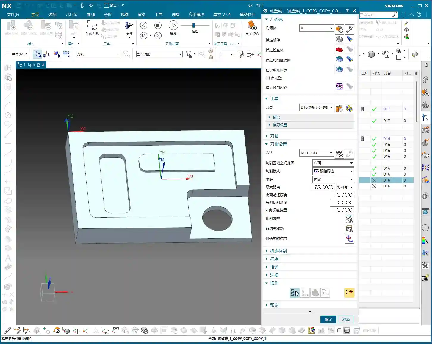
- Step One: Zero out bottom face stock allowance. During roughing, you definitely left stock on the bottom face, say 0.2mm. For the finishing pass, you must change “Part Stock” or “Bottom Stock” directly to 0. This ensures the tool cuts precisely to your defined bottom face, making it a single, accurate pass with no remaining stock.
- Step Two: Sidewall stock allowance. If you plan to finish the bottom face and sidewalls separately, when finishing the bottom face, you can leave a slightly larger sidewall stock allowance, for example, 0.3mm. This prevents the tool from grazing the sidewalls during the bottom face finishing pass, avoiding secondary tool marks. If the pocket is shallow, you can finish both the bottom and sidewalls together, setting all allowances to 0. But for now, we’ll discuss them separately, so follow my lead.

Solving High Z-Approach in Enclosed Areas
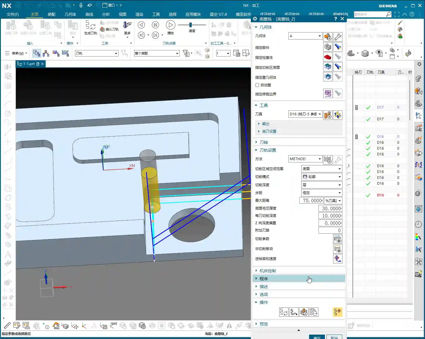
This is a common mistake newcomers make, and it’s not always thoroughly explained in textbooks. You might notice that in some enclosed cavities, the tool starts its entry from a high position, plunging vertically, sometimes even dropping from over ten millimeters – it sounds painful and can easily chip the tool!
- Root Cause: This happens because the “Part Stock” (sometimes called “Safety Height” or “Initial Cut Depth”) you set during roughing was too large. For example, if you set it to 10mm for roughing, the finishing pass will default to starting its cut from that same high position.
- Master Wang’s Tip: Listen up. In your finishing program, locate the parameter that controls the tool’s starting Z-height for engagement. This is typically “Part Stock” or a similar setting like “Safe Entry Height”. Reduce it significantly, for example, to 1mm. This way, the tool will approach the workpiece surface much closer before engaging, which is safer, more efficient, and eliminates unnecessary air cutting time.
- Exception for Open Areas: If it’s an open area where the tool enters from outside the part, this issue of high Z-approach is irrelevant, as the tool won’t be plunging from above in the same way.
Finishing Pass for Sidewalls: Contour Cutting is Key
With the bottom face taken care of, let’s move on to the sidewalls. Finishing sidewalls requires much more finesse than bottom faces, especially regarding smoothness and tool mark control.

New Program: Finishing Sidewalls from Scratch
While I, Master Wang, typically copy and modify programs, to ensure you fully understand, we’ll create a new sidewall finishing program from scratch. Select the “Planar Mill” operation type, and continue using our D16 end mill.
- Select Machining Face: For instance, if we’re finishing this sidewall, select the bottom face it originates from – essentially, the “root” of the sidewall.
- Problem Alert: If you generate the tool path directly, you’ll notice it’s still finishing the bottom face! Why? Because “Planar Mill” defaults to machining bottom faces.
Core Setting: Switch Cutting Pattern to “Contour”
Listen up, this is the most critical step for finishing sidewalls!
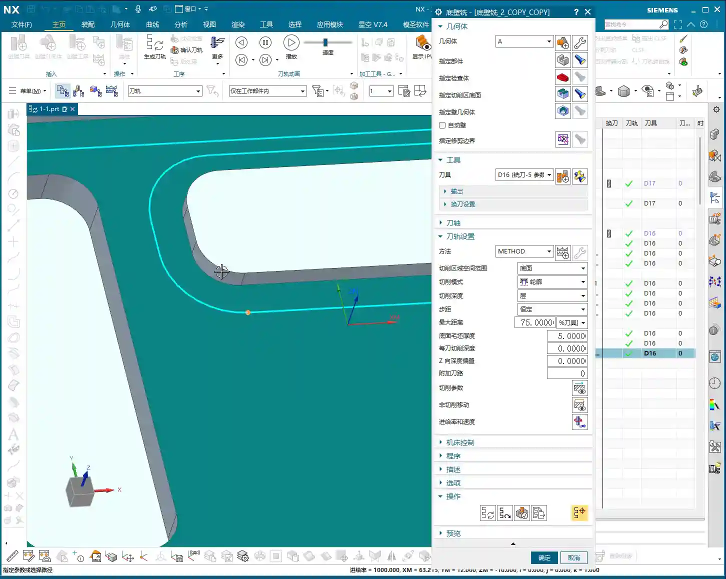
- Key Operation: In your program parameters, find the “Cutting Pattern” option. Decisively switch it to “Contour” from the default “Follow Part,” “Zigzag,” or other options.
- Explanation of Function: Once you switch to “Contour” mode, Siemens NX will intelligently identify all sidewalls perpendicular to your selected bottom face and machine along their profiles.
- Zero Stock Allowance: Similarly, for sidewall finishing, set all stock allowances (including bottom and sidewall stock) to 0. We want that crisp, clean finish!
Optimizing Lead-in/Lead-out: Ditch Angled Plunge, Embrace Smooth Arc Engagement
Even after setting the “Contour” mode, you might find the tool engaging at an angle. While it can still cut, this isn’t very efficient and tends to leave marks at the entry point, affecting surface finish.
- Step One: Address the “angled plunge” phenomenon.
- The Pain Point: The tool plunges into the material at an angle instead of vertically descending to the cutting plane and then linearly engaging. This is especially noticeable in enclosed areas.
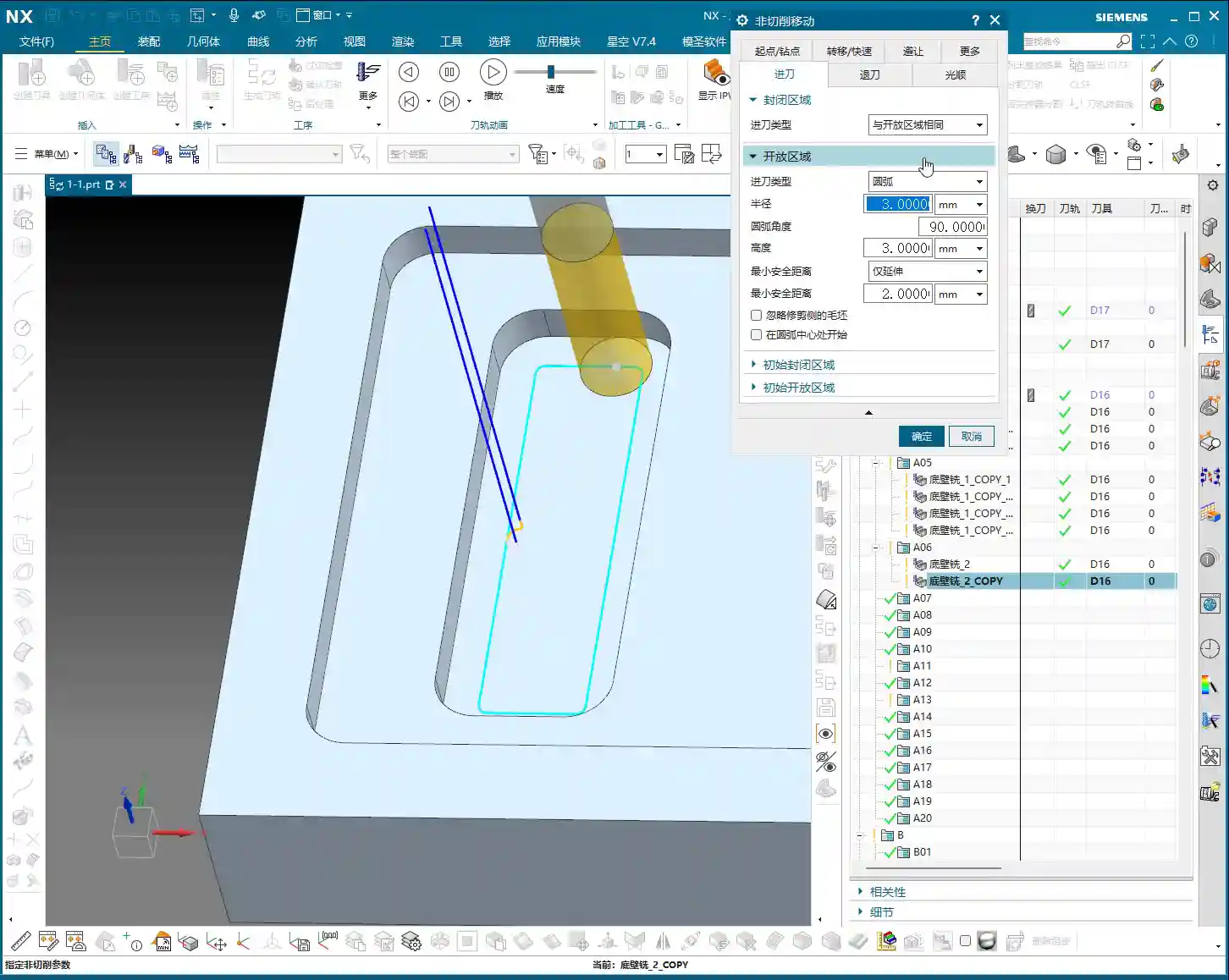
- Master Wang’s Tip: Go to the “Non-Cutting Moves” settings. There’s a parameter related to the entry method, often called “First Point of Yellow Line” (or “Engage Method”). Typically, it defaults to calculating for “Enclosed Areas.” You need to change it to “Same as Open Area”. This way, the tool will first descend to the cutting plane and then linearly engage, which is much safer.
- Step Two: Ensure smoother engagement and eliminate tool marks.
- The Pain Point: Even after fixing the angled plunge, a straight-line entry after vertical descent can still cause impact, leading to subtle tool marks.
- Master Wang’s Tip: In the “Engage Type” setting, change “Linear” to “Arc”. Then set an appropriate arc radius, for example, 3mm. This allows the tool to smoothly engage the workpiece along an arc trajectory, minimizing impact and naturally improving surface finish.
- Arc Extension (“Arc End Extension”): When using arc engagement, there’s also an “Arc End Extension” parameter. You can think of this as the extended length of the arc during lead-in or lead-out. For example, if you set it to 10mm, the tool will travel an additional 10mm along the arc before entering or after exiting the cut. What’s its purpose? It ensures the tool fully enters the cut or completely exits the material, preventing tool marks or incomplete machining in critical areas. There’s no fixed value; just observe the machining effect and adjust as you see fit.
- Overlap Distance: The “Overlap Distance” is also very useful. For example, if you set it to 5mm, the tool path will extend by 5mm at connections or where the path loops back on itself, creating an overlap region. This effectively eliminates tiny unmachined areas and ensures overall machining consistency. Of course, not overlapping is also fine; it depends on your actual working conditions and precision requirements.

Master Teaches You: Finishing Complex Part Sidewalls in One Go
You might be thinking, if a part has many sidewalls, do I have to select them one by one? That would be exhausting! Master Wang tells you, there’s no need for such hassle.
One Trick for Many Uses: The Ingenious Application of Planar Mill with Contour Cutting
Our previously created sidewall finishing program already has the “Contour” cutting pattern and optimized lead-in/lead-out methods set up. Now, if you need to finish a sidewall with a more complex structure, such as one with grooves or multiple edges, how do you do it?
- Quick Copy: Simply copy your previously optimized sidewall finishing program.
- Select New Bottom Face: Then, you just need to select the bottom face corresponding to the new sidewall. For example, for the sidewalls of a square boss, you’d select the top face of that boss as the machining bottom face.
- Intelligent Recognition: A miracle happens! Because you selected the “Contour” cutting pattern, Siemens NX will automatically identify all sidewalls around this bottom face and generate tool paths for finishing them. One bottom face, and all surrounding sidewalls are taken care of – saving time and effort!

Acceptance Criteria: How to Determine if a Part is “Finished Correctly”
No matter how well your program is written, the final result depends on the machining effect. How do you determine if the bottom faces and sidewalls are truly “finished correctly”?
Visual Verification: Look at the Simulation, But More Importantly, the Cutting “Footprints”
Don’t just stare at the software simulation; that’s just theory. Us old masters have our own trick: observing the tool path simulation’s “footprints.”
- For Bottom Faces: In the Siemens NX tool path simulation, slow down the simulation speed and carefully observe the marks left by the tool as it passes over the bottom face. If you see a layer of uniform, subtle “overlap footprints” on the bottom surface, it indicates that the tool has thoroughly machined the bottom face. The more uniform these “footprints,” the better the surface finish.
- For Sidewalls: Using the same method, drag the tool path and look for those tiny tool marks or overlapping trajectories. If these marks are clear and continuous, it means the sidewall finishing pass has also covered the entire area. If you find any areas without “footprints,” or if the “footprints” are not continuous, you’ll need to go back and check your parameters – perhaps the stock wasn’t removed completely, or the tool path didn’t fully cover the area.
That concludes our lesson for today. Next time, we’ll discuss how to handle hole machining. Remember, practice makes perfect; keep practicing and keep thinking!
Summary: Pitfall Avoidance Guide
- Zero stock allowance is an ironclad rule: For finishing any surface, the corresponding machining stock allowance must be set to 0, or all your efforts will be in vain.
- Exercise caution with Z-approach in enclosed areas: Don’t let the tool plunge directly from a high position. Be sure to adjust “Part Stock” or “Safe Entry Height” to around 1mm to reduce impact.
- For sidewall finishing, “Contour” cutting pattern is mandatory: This is the core of Siemens NX’s “Planar Mill” for finishing sidewalls; get this wrong, and you won’t be finishing the sidewalls.
- Optimize lead-in/lead-out; smoothness is paramount: Set “First Point of Yellow Line” to “Same as Open Area,” select “Arc” for the engage type, and reasonably set the arc radius and extension to eliminate tool marks and ensure surface quality.
- Set overlap distance appropriately: Especially in critical, high-requirement sidewall areas, proper overlap can prevent missed cuts and improve overall surface finish.
- Learn to “read the footprints”: Don’t just rely on the simulation; learn to judge if the actual machining is complete by observing the subtle marks in the simulation. This is a true skill taught by experienced masters!
“`
👤 About the Author:
The author is a veteran CNC machining professional with 15 years of industry experience, specializing in UG NX programming. This article is an original work representing personal practical insights.
⚠️ Copyright Notice: Unauthorized reproduction or distribution without prior communication is strictly prohibited.
Leave a Reply