Tag: NX Programming

  • NX Point-on-Curve Engraving: Master Wang’s Practical Guide to Mastering 3D Surface Engraving, Breaki

    📝 Key Takeaways: Master Wang will take you through a practical breakdown of the “Point-on-Curve Engraving/Line Engraving” function within NX Fixed Contour Milling to overcome planar machining limitations and easily achieve precise 3D engraving on complex surfaces. Master tool selection, negative stock depth control, and multi-pass strategies to uncover practical tips not found in textbooks, and help you become a CNC programming master!

    Master Wang Speaks: Practical Applications of Point-on-Curve Engraving

    Listen up, youngsters. Today, I, Master Wang, will properly explain the “Point-on-Curve Engraving” and “Line Engraving” functions within NX Fixed Contour Milling. Don’t underestimate this feature; it’s a powerful tool for engraving text and lines on complex surfaces, far superior to those 2D engraving methods that only “scratch the surface” on flat planes!

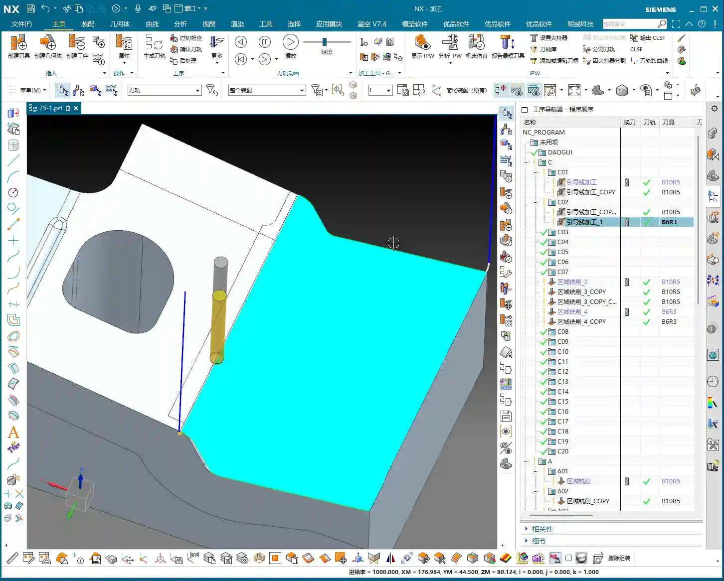
    Simply put, “Point-on-Curve Engraving” is the “upgraded 3D version” of the “Profile Engraving” we learned before. Standard profile engraving is limited to flat surfaces, but “Point-on-Curve Engraving”? It allows you to engrave text and lines on curved surfaces, inclined surfaces, or any lines on 3D geometries – now that’s real skill! Don’t just stare at the perfectly flat machining surfaces in the software; how many actual parts have that many flat areas for you to work with? Whether you’re engraving a company logo, product model, or alignment lines, this method delivers high efficiency and excellent results.

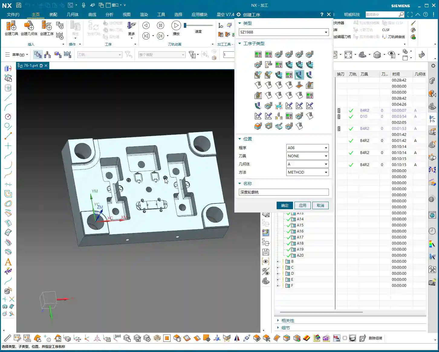
    Operation Core: Select Face, Select Curve, 3D Engraving Made Easy

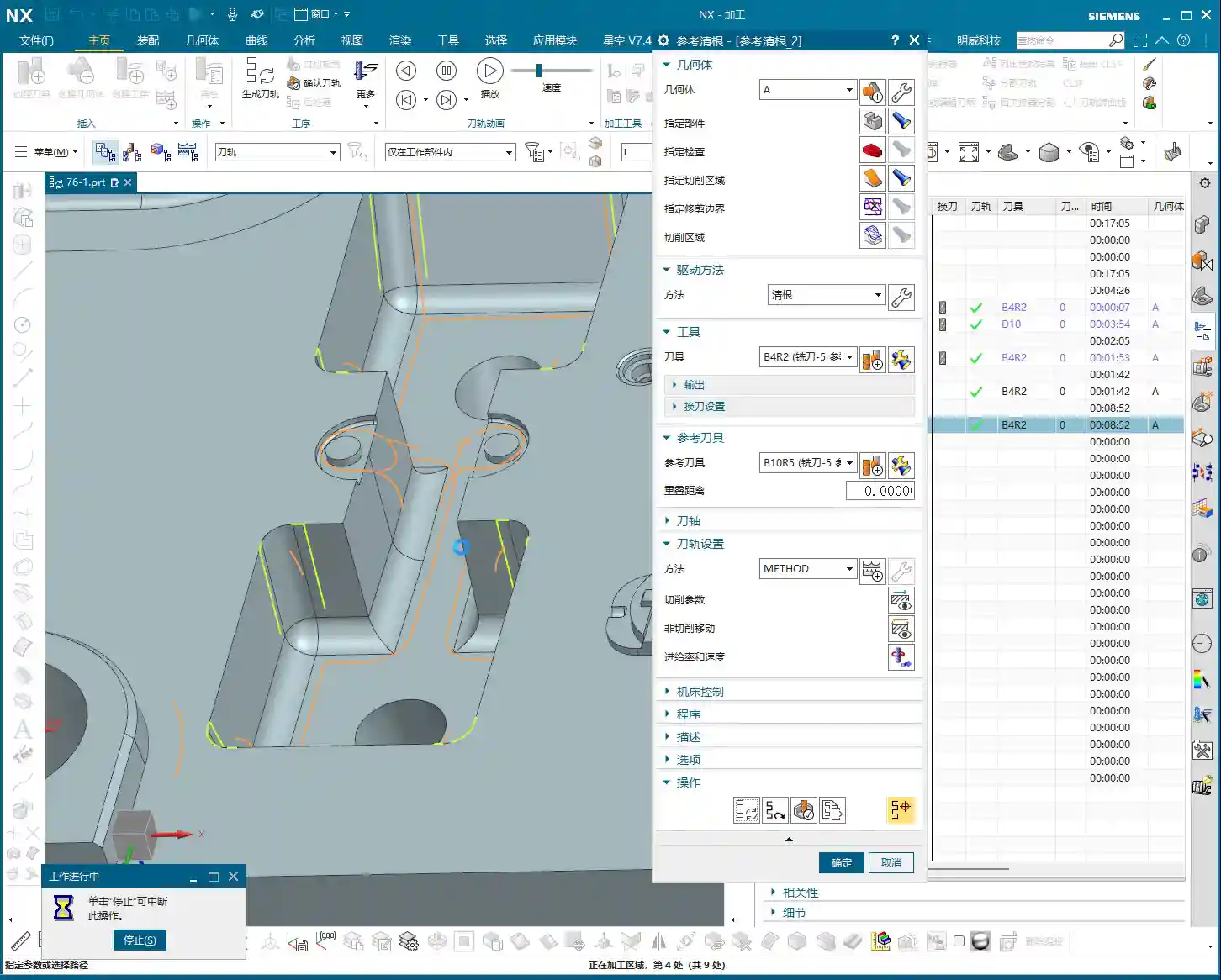
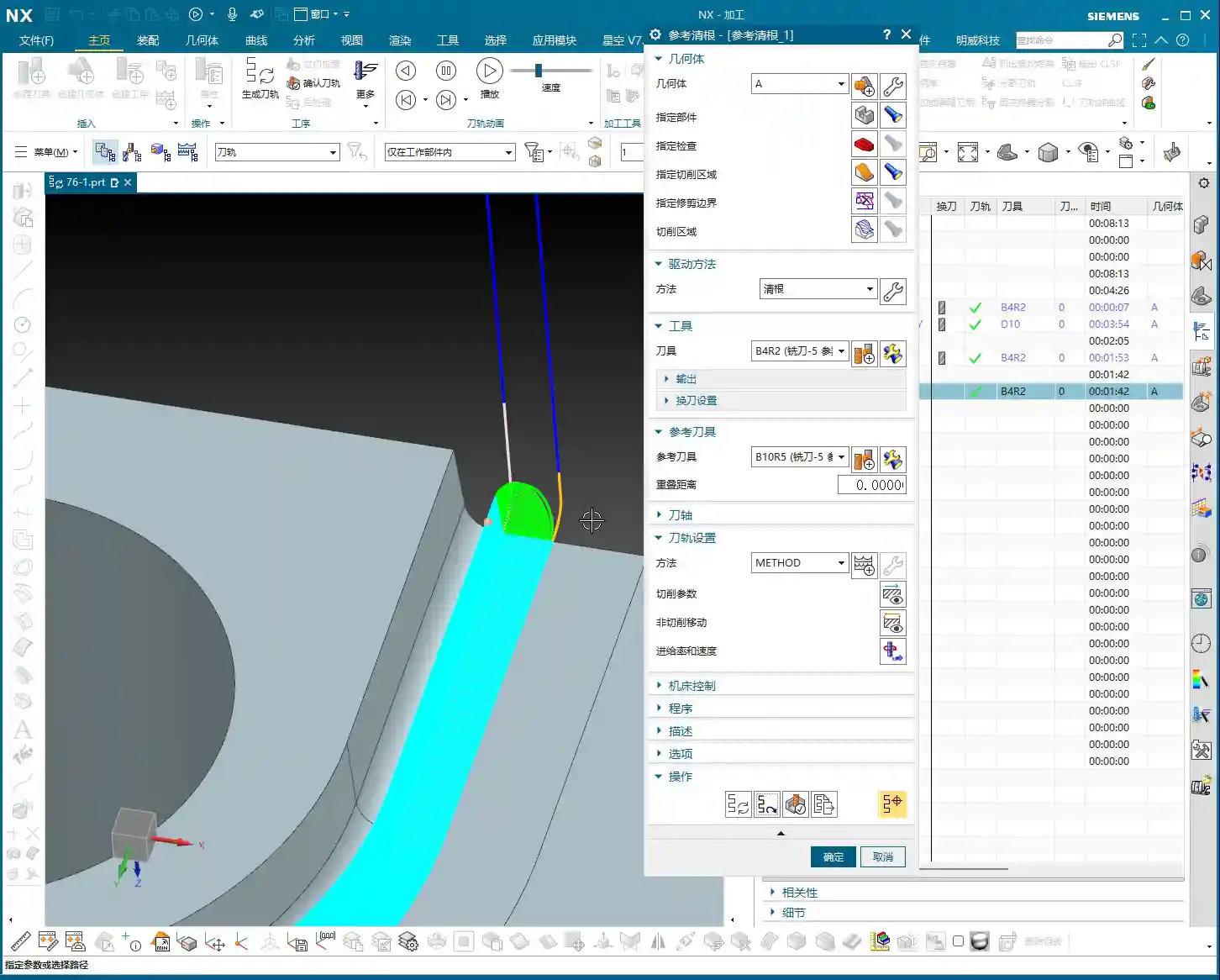
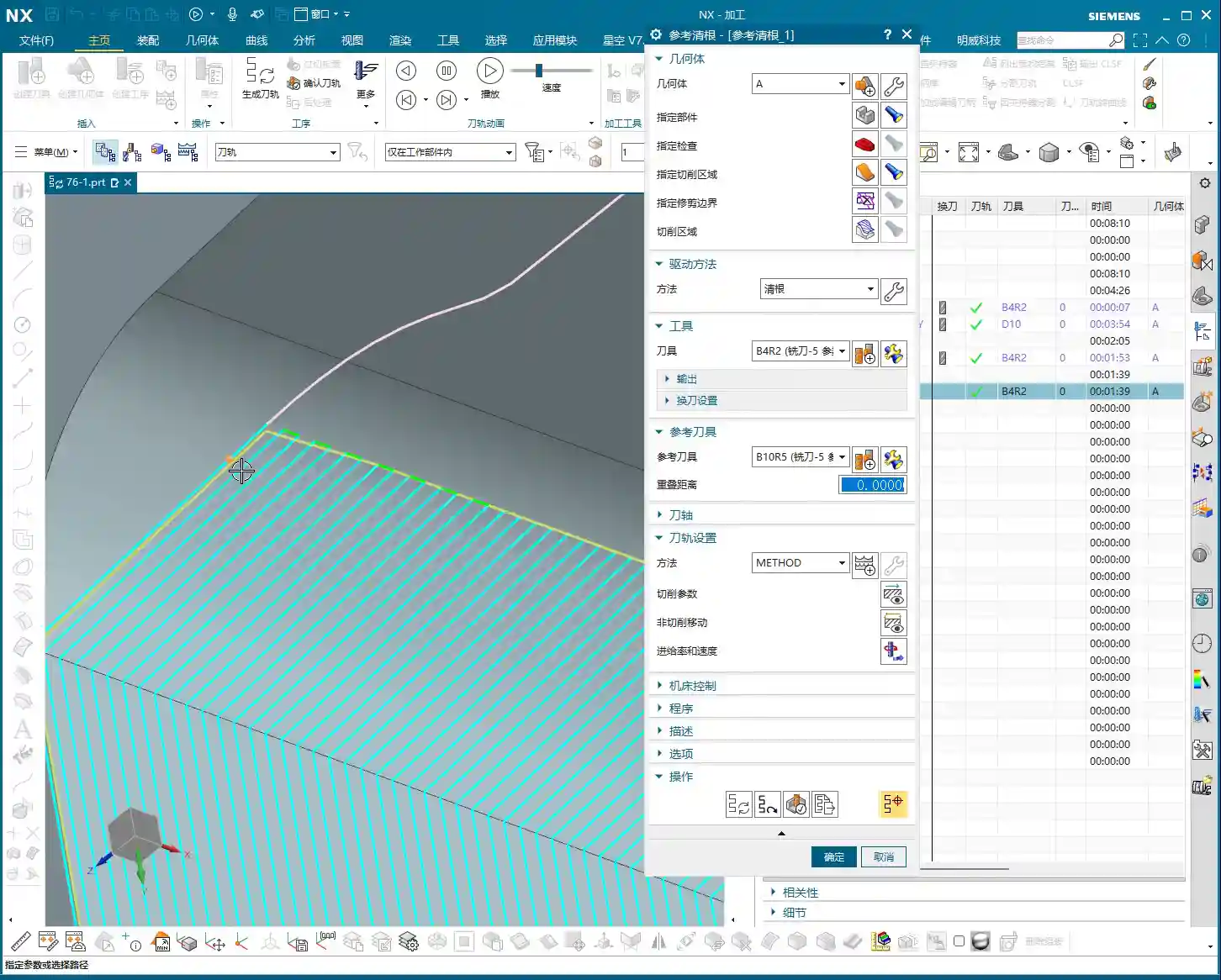
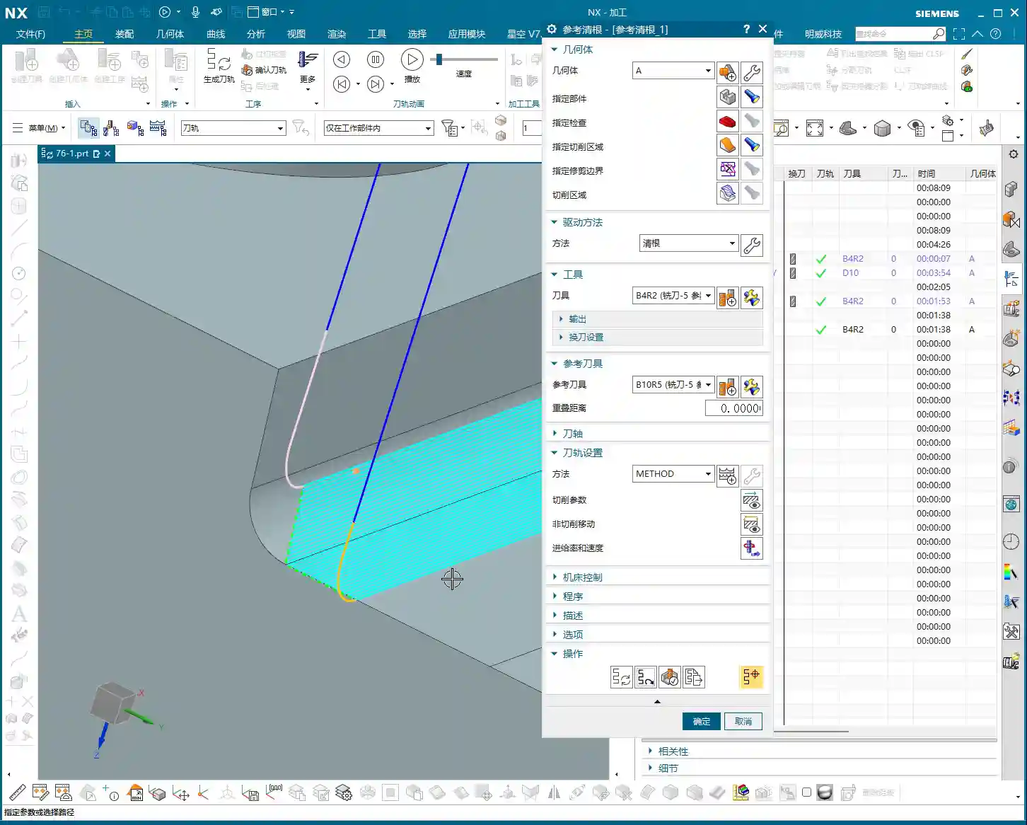
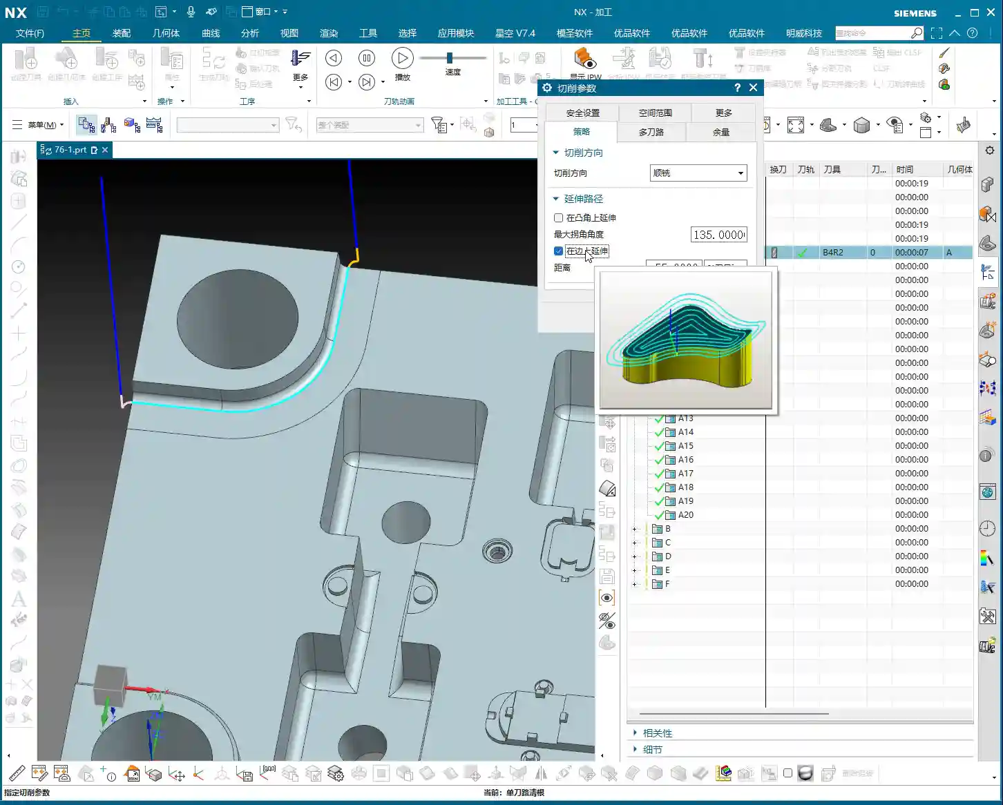
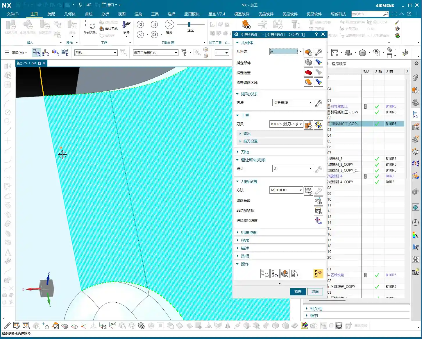
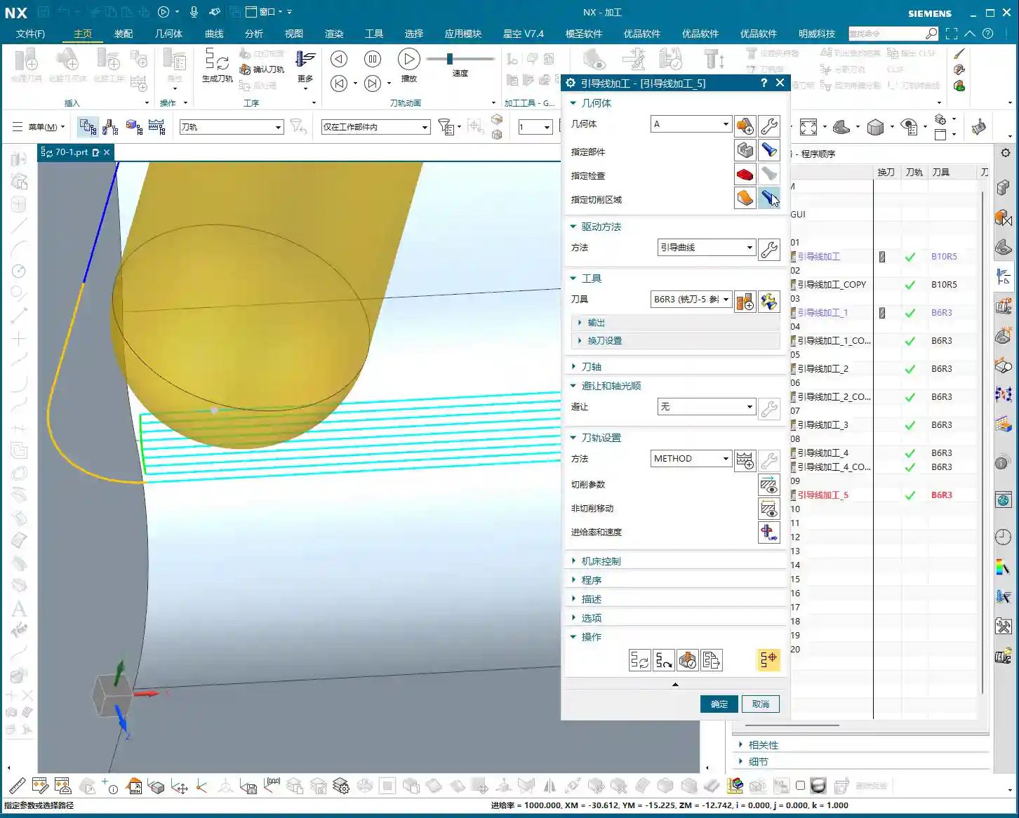
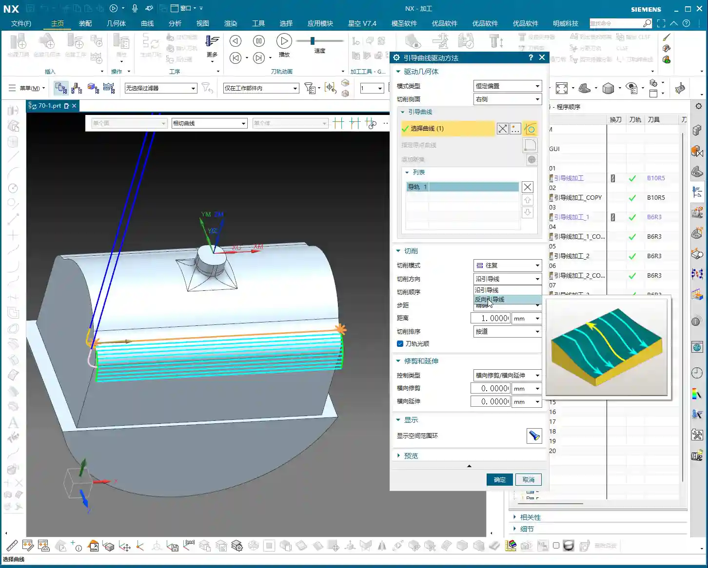
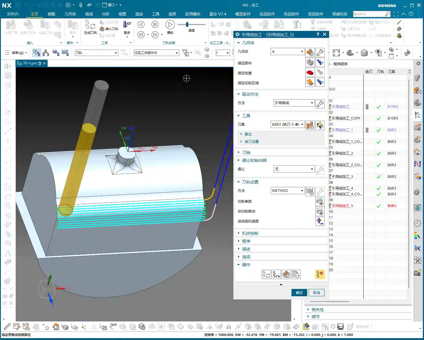
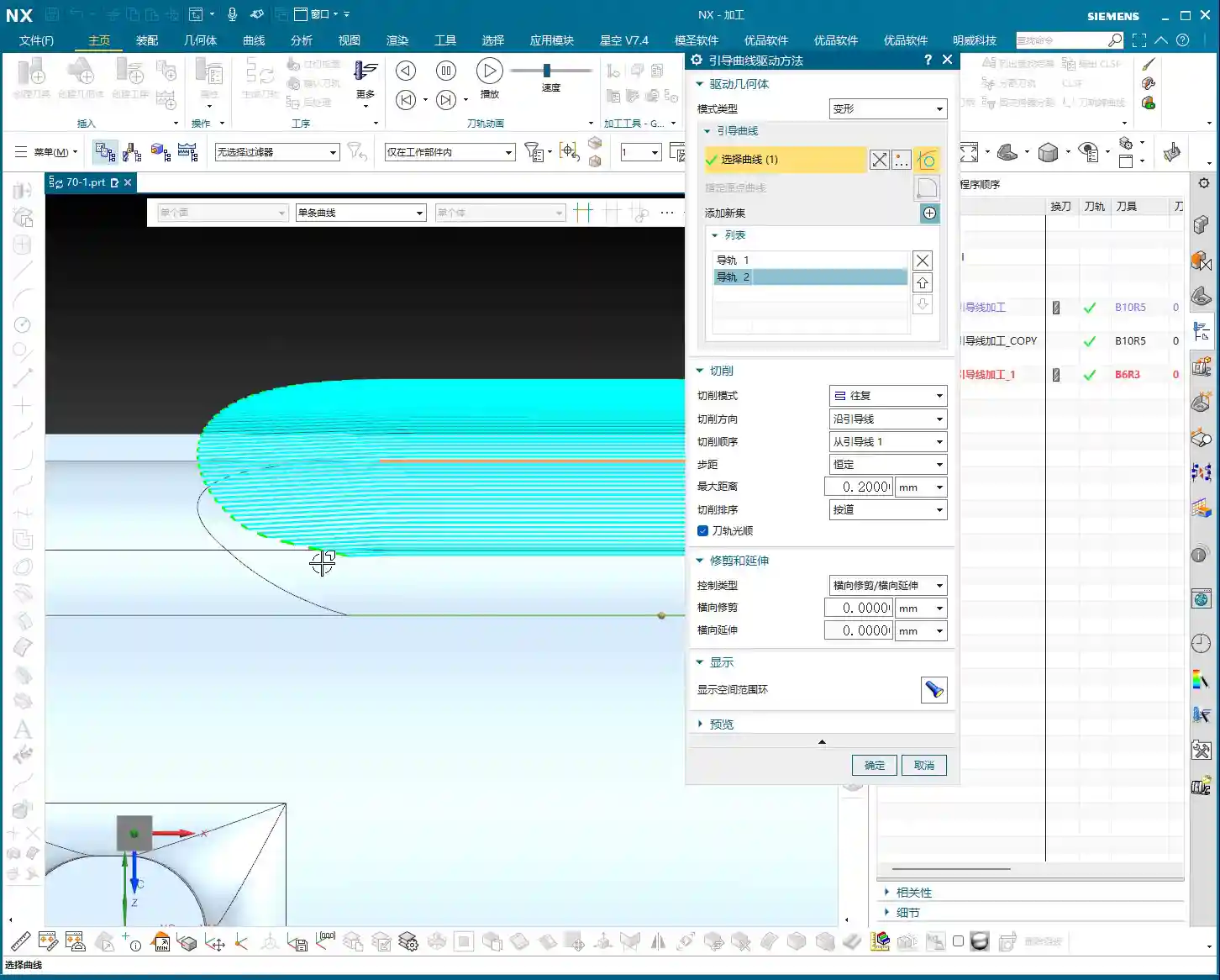
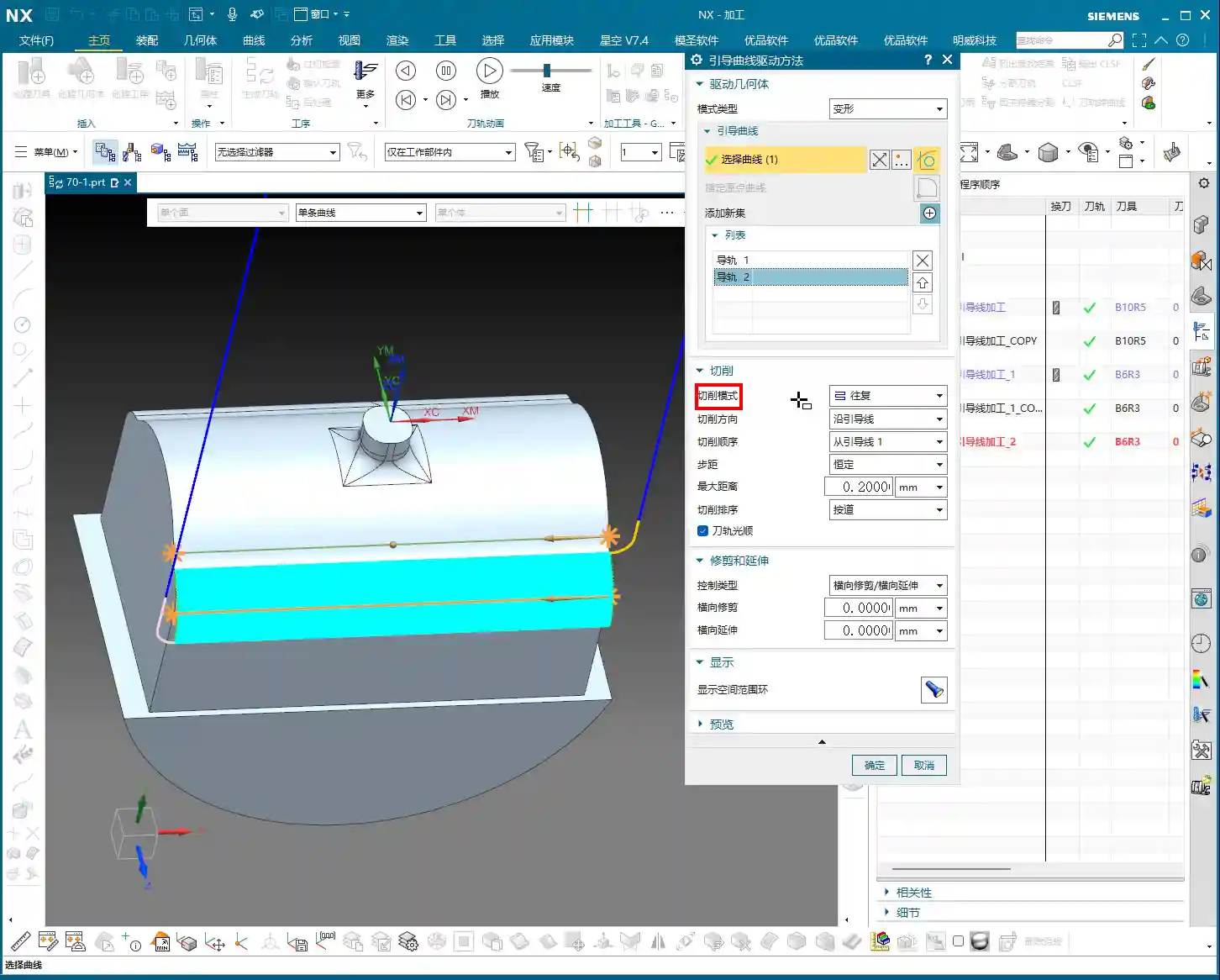
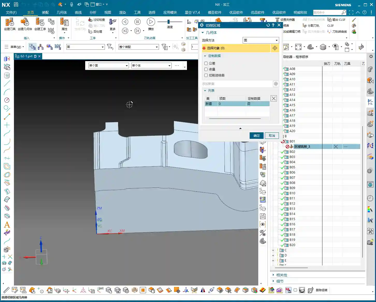
    Using this function is actually quite simple, with two core steps: First select the face, then select the curve.

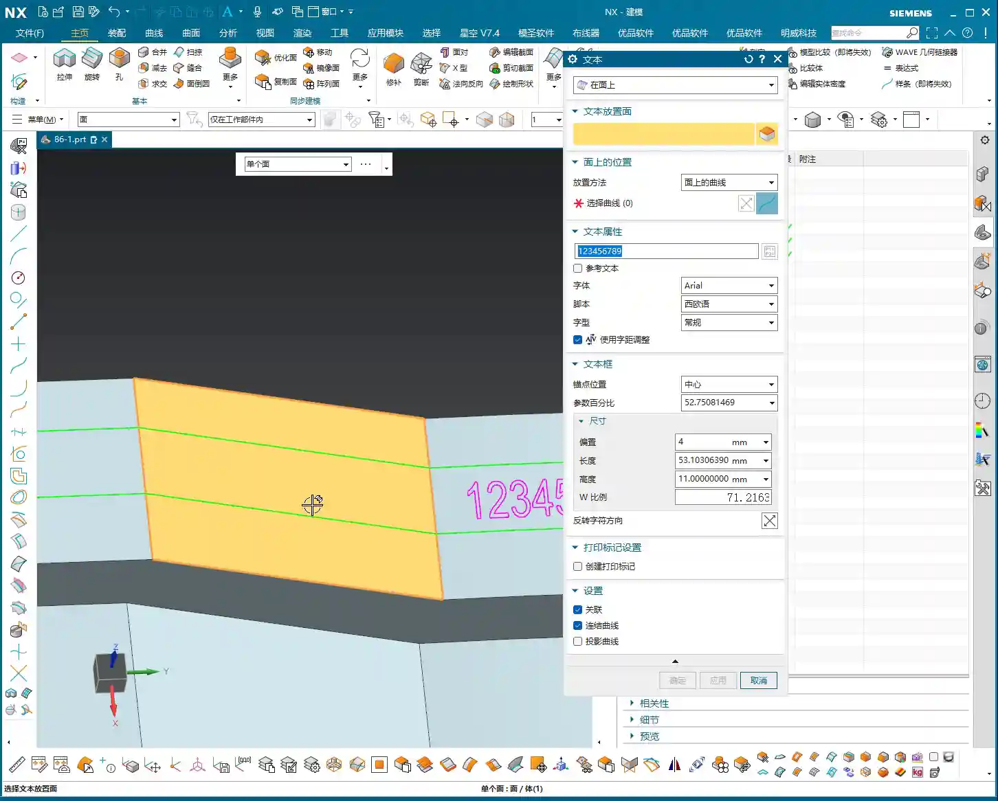
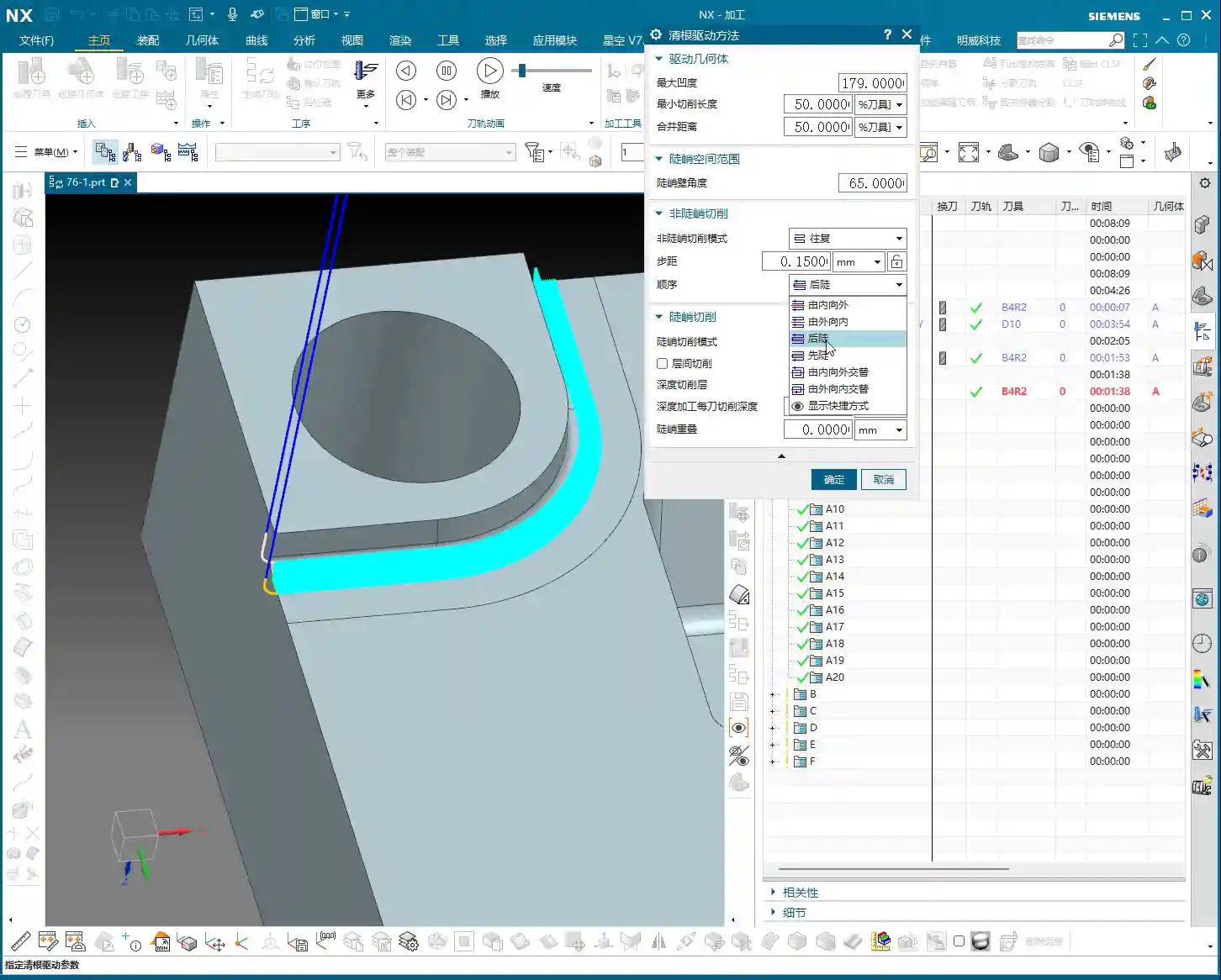
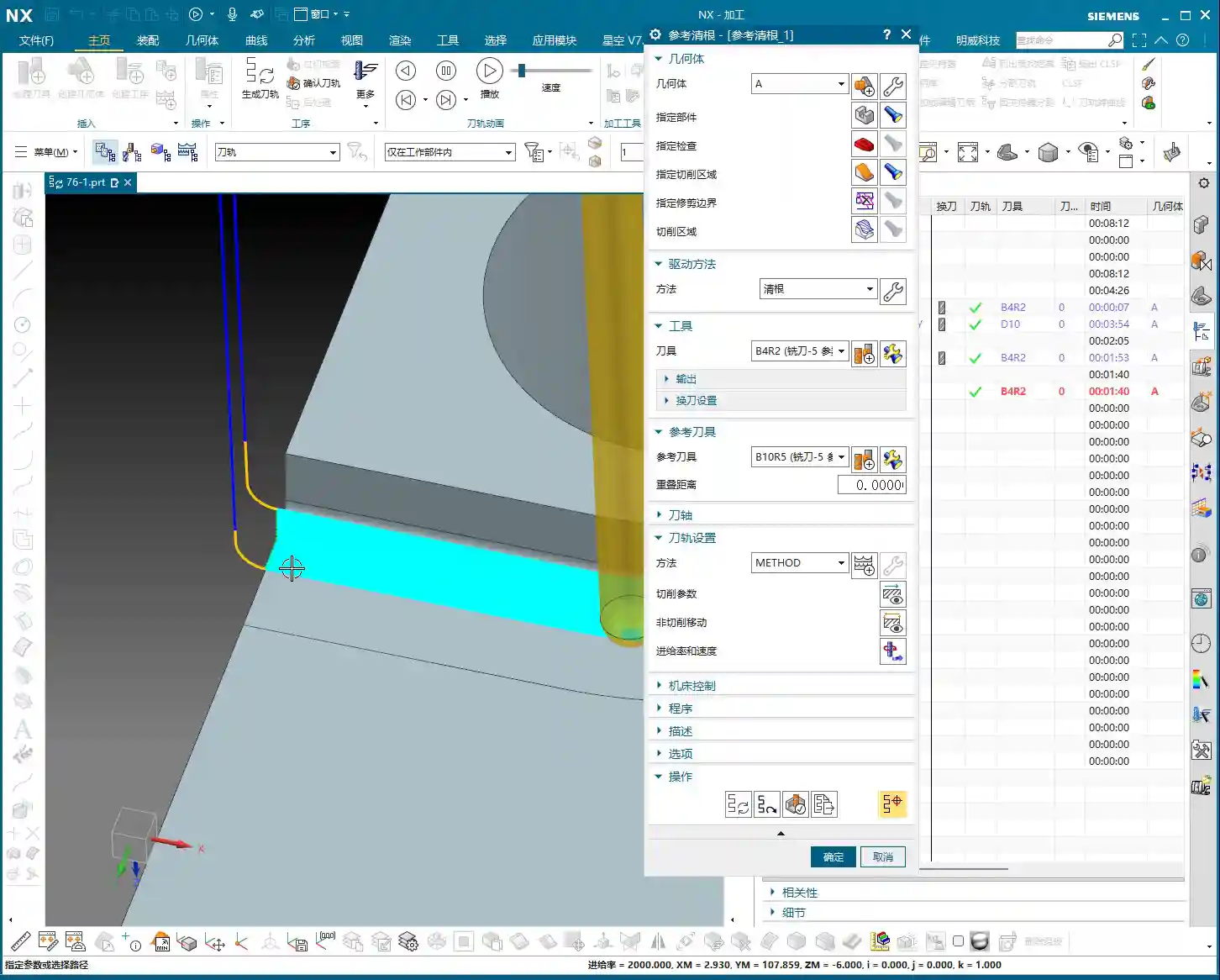
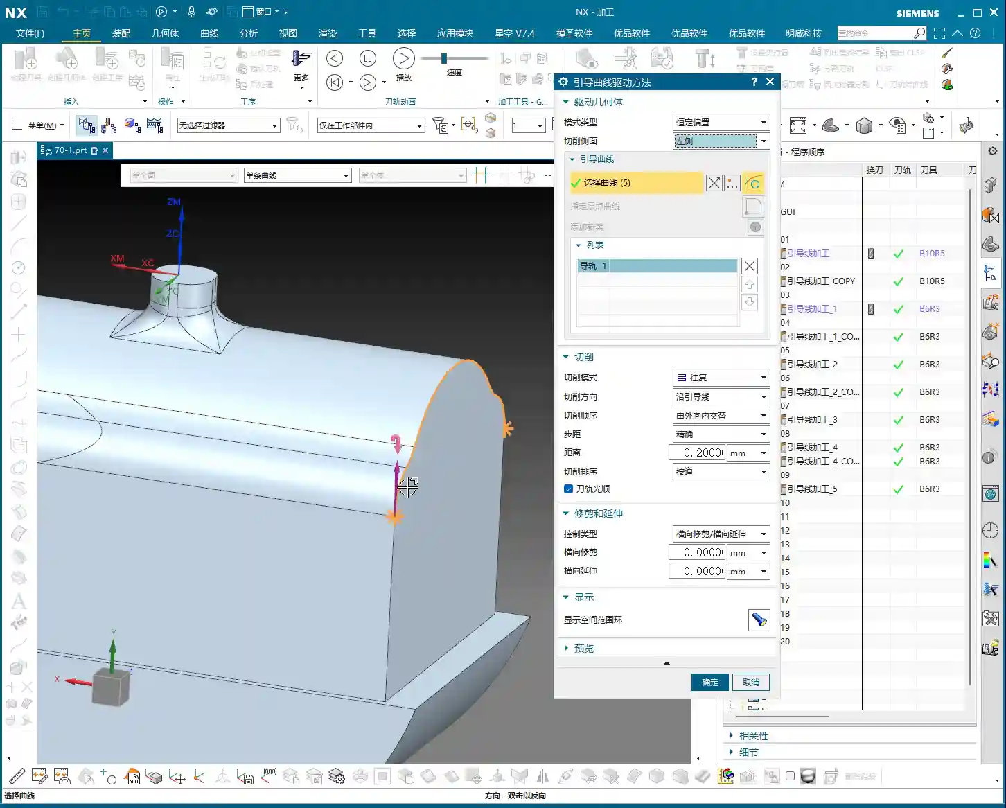
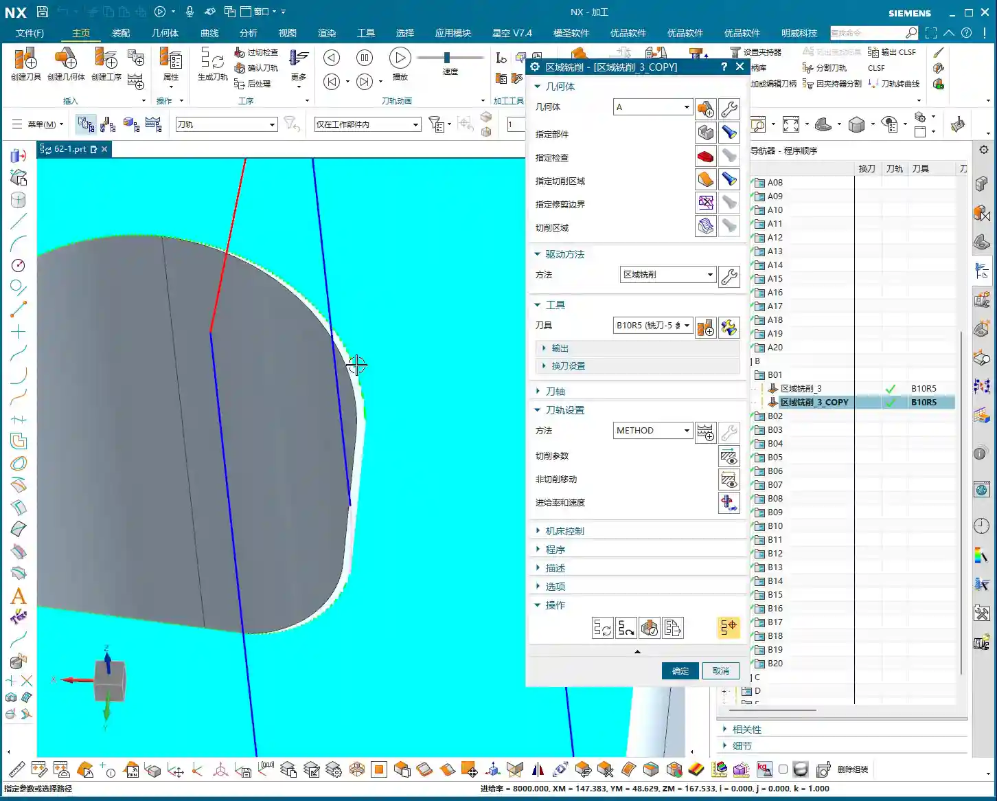
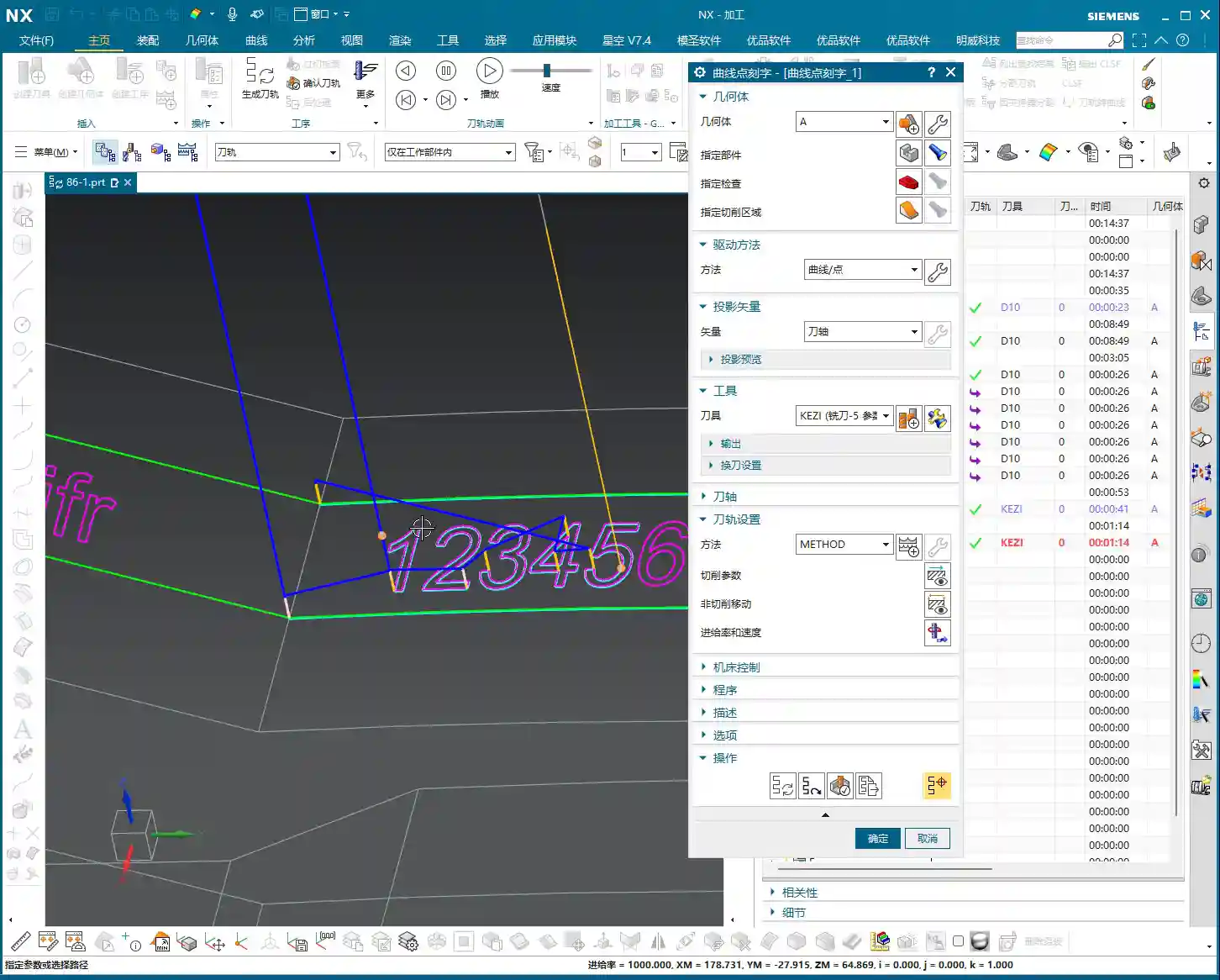
    • Step One: Select the Machining Face. Tell the software which area you want to engrave on. Even if the face is curved or inclined, NX can handle it for you.
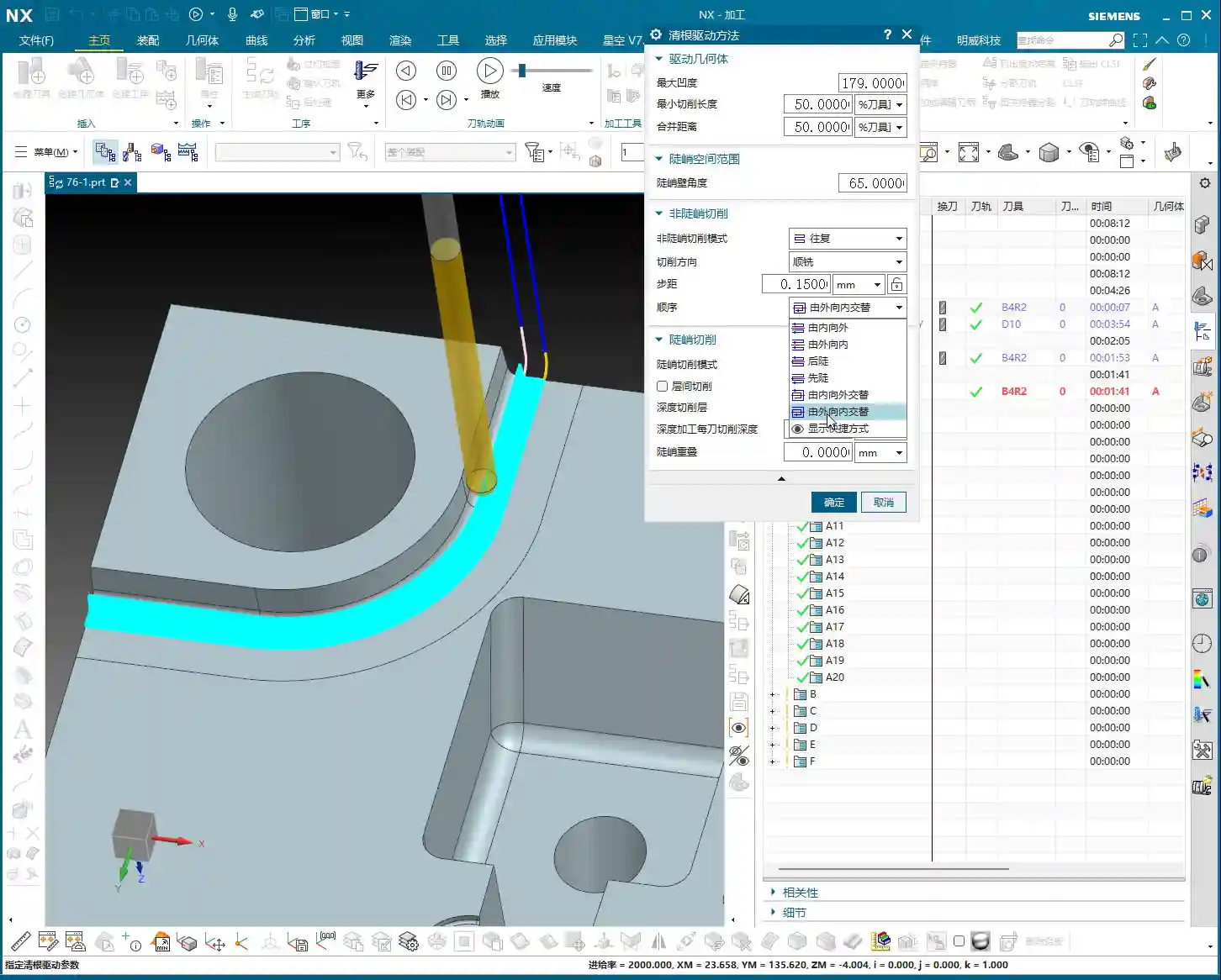
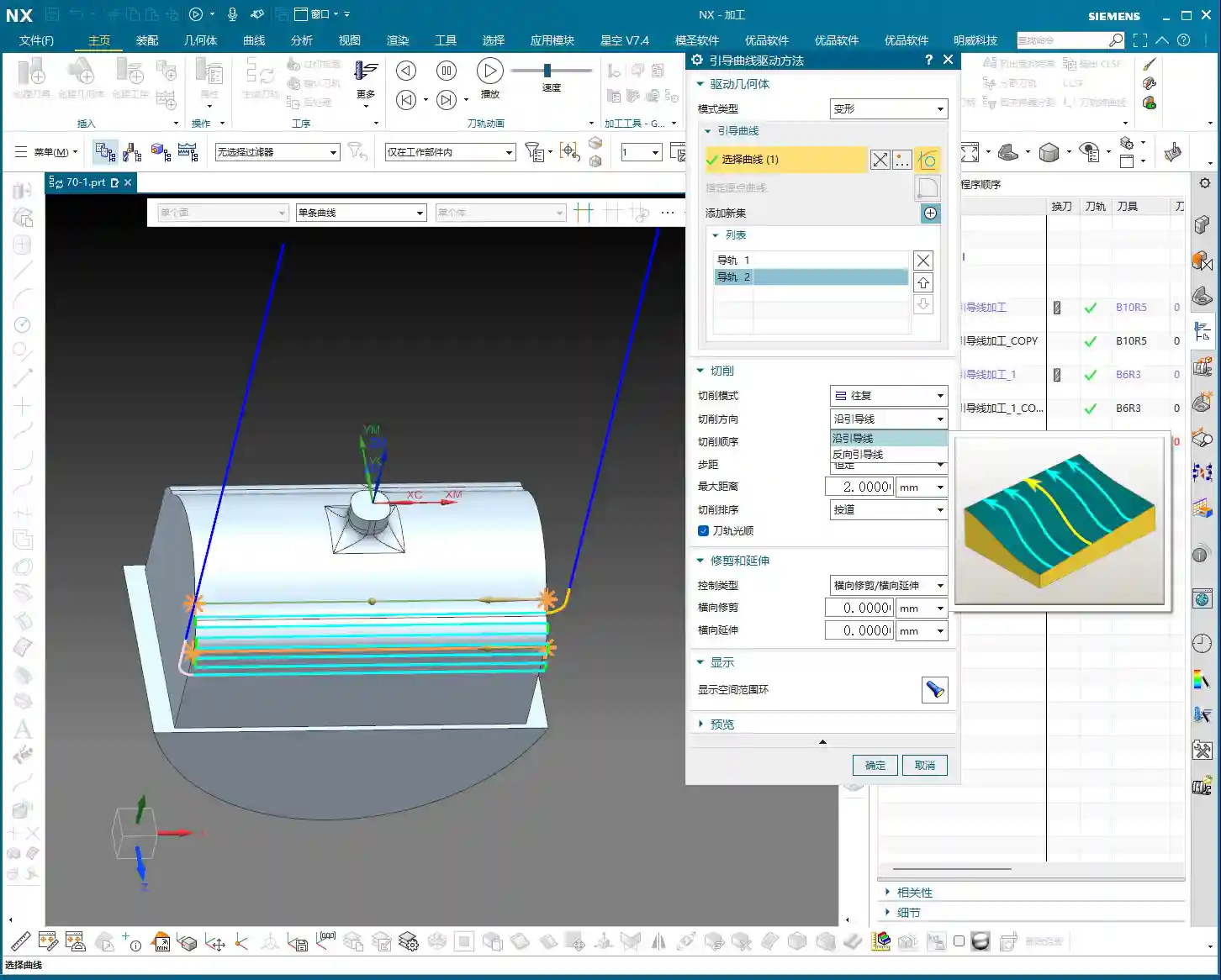
    • Step Two: Select the Curve to Engrave. This curve can be one you’ve drawn on a surface, or a line from another plane; NX will help you project it onto your selected face for machining. Wrong direction? Just click ‘Reverse’ – no need to overcomplicate things.

    Master Wang’s Tip: Remember, select the face first, then the curve; this is the operational logic in NX. Don’t try to do everything at once; take it one step at a time to stay steady. It’s the same principle as machining parts – you can’t mess up the sequence! Once you’ve selected the face and then the curve, even if that curve isn’t originally on the face, the software will “press” it onto the surface and engrave it for you. Now *that’s* practical application you won’t learn from textbooks.

    Tooling and Parameters: The Art of “Micro-Management” in Practice

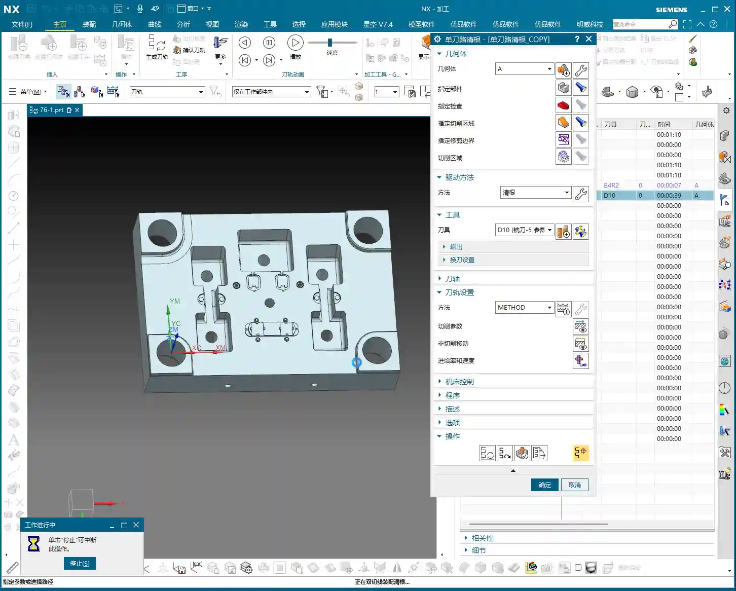
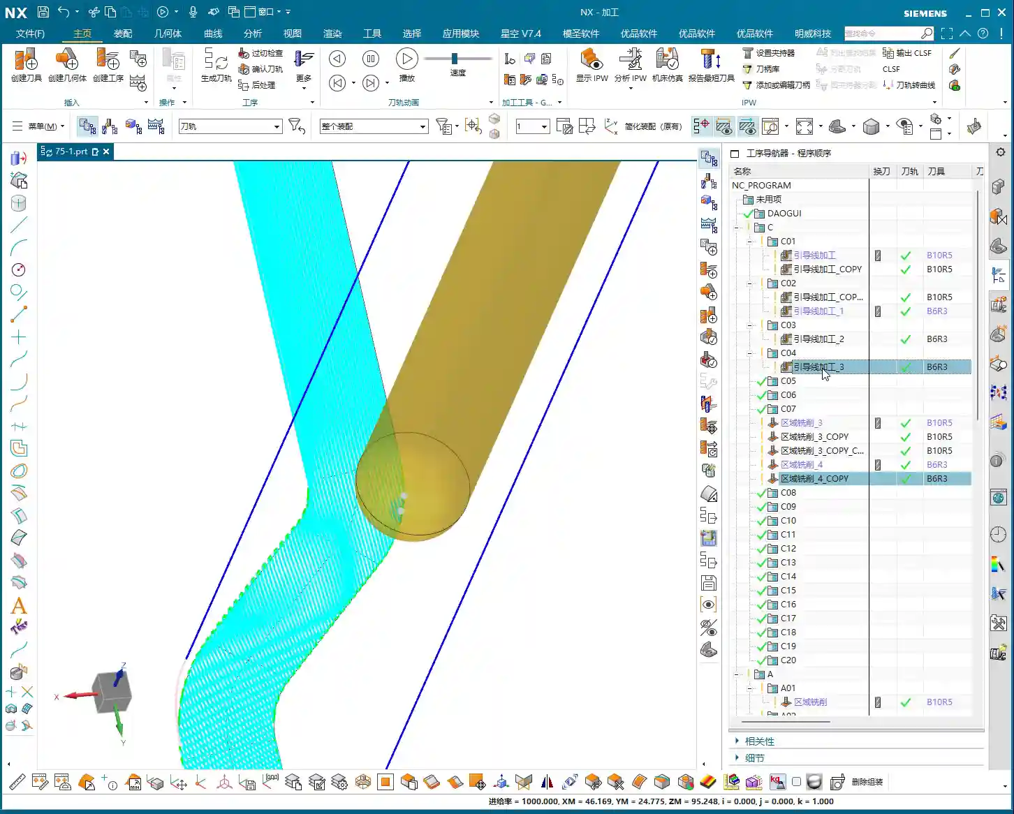
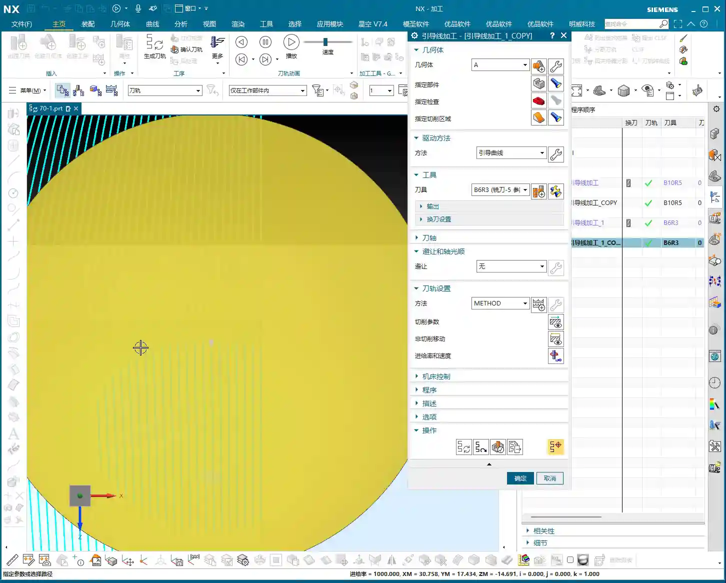
    Selecting the Right Engraving Tool

    Tools for engraving text and lines are typically quite small, often what we in the shop call “needle-point tools,” such as conical engraving tools with a diameter of 0.3mm to 0.5mm (approx. 0.012-0.020 inch). When selecting a tool, base your choice on the required engraving depth and width. The finer the tool, the more delicate the engraving, but its rigidity also decreases, so you need to pay close attention to the cutting parameters. Ensure your feed rate and spindle speed are well-matched. This area is prone to excessive tool loading or breakage, so don’t be stingy with the time; breaking a tool will cost you far more in the long run.

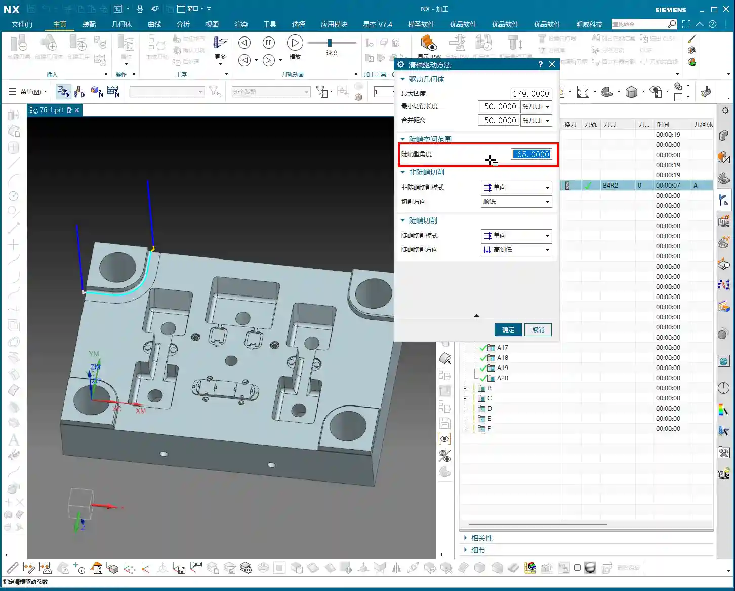
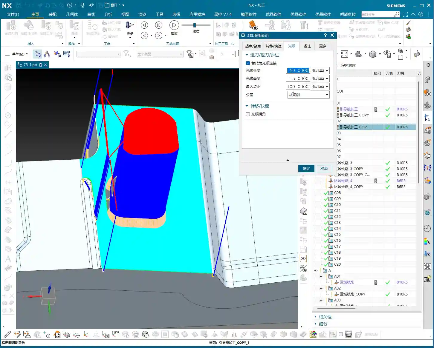
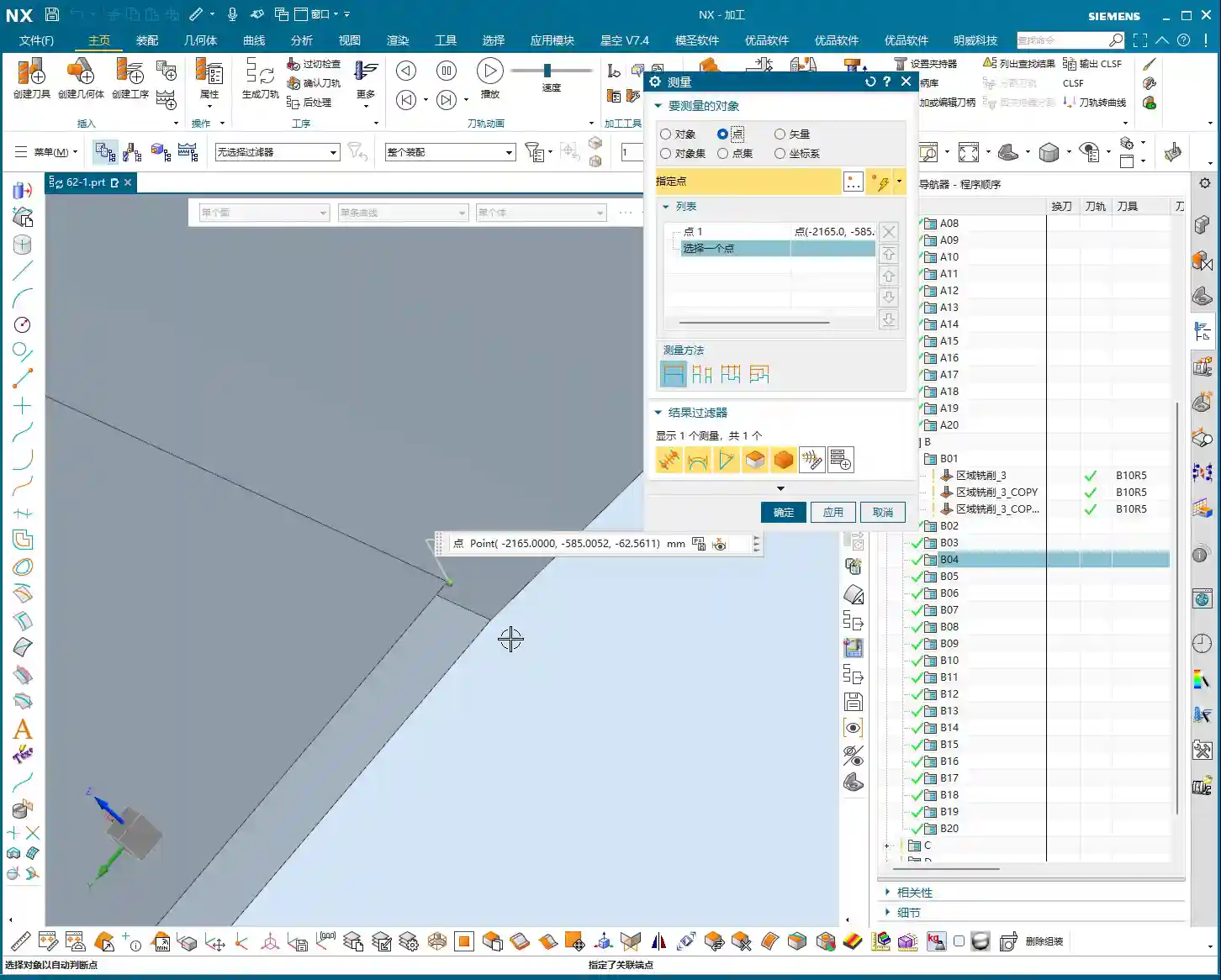
    The Secret of “Negative Stock”: The Mystery of Depth Control

    When using this function, you might encounter a “negative stock” warning. Don’t panic! It’s a little trick we leave when setting up templates.

    Listen up: this “negative stock” means we instruct the tool to descend slightly deeper than the theoretical path to achieve the actual engraving depth. For example, a -0.1mm (approx. -0.004 inch) stock allowance set in the template means the tool will cut 0.1mm deeper than the surface. This way, you truly “engrave” rather than just scratching the surface. This is crucial for ensuring the depth and clarity of the engraving. In practice, this parameter needs to be flexibly adjusted based on the material, tool, and desired final effect. Don’t just rely on software simulations; observe the cutting sparks, listen to the cutting sound. Actual tool wear and machine accuracy will both affect the depth. When necessary, manually adjust the compensation; that ±0.005mm (approx. ±0.0002 inch) precision isn’t something software alone can guarantee.

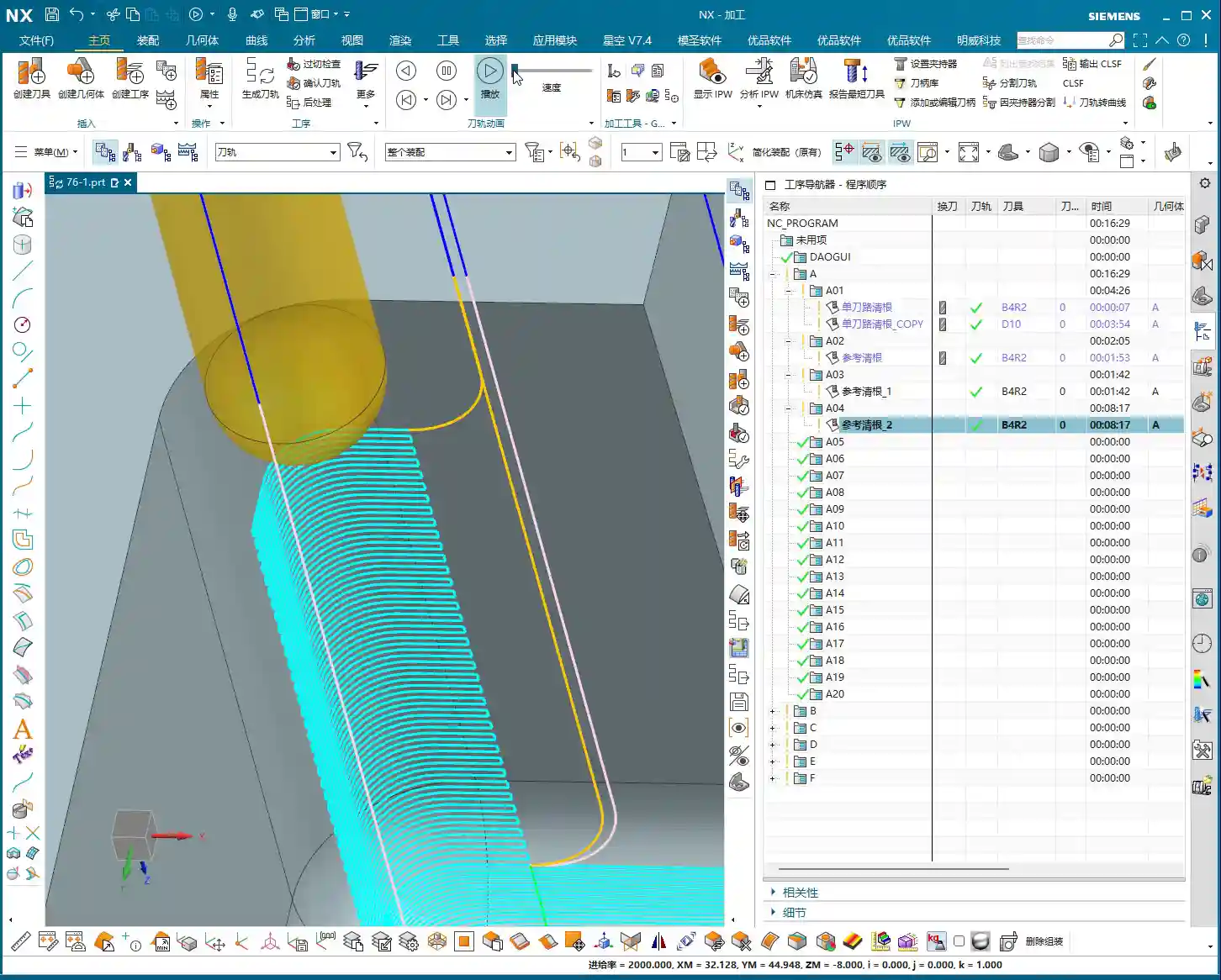
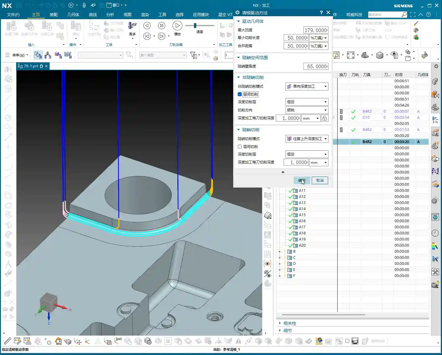
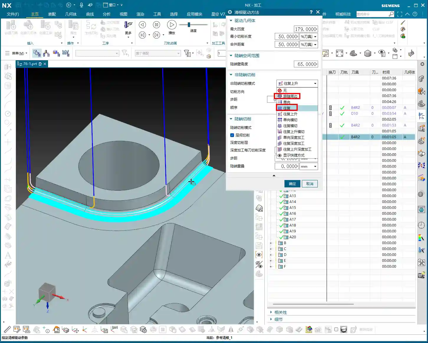
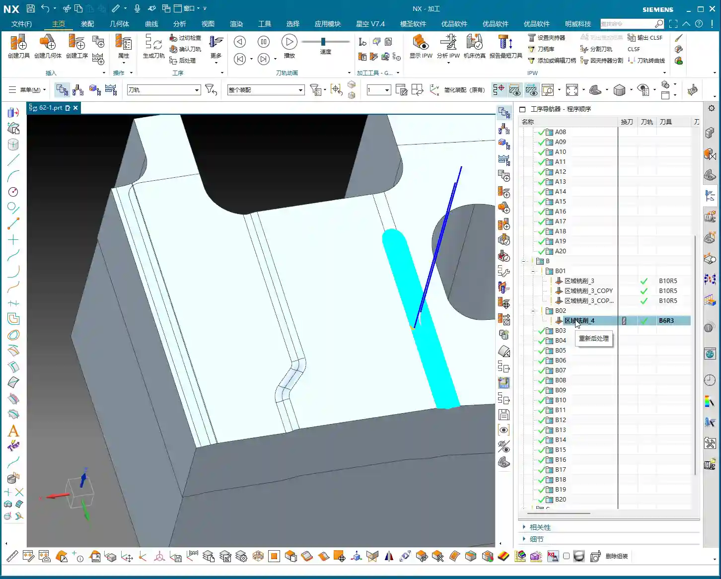
    Multiple Passes: Layered Progression for Fine Engraving

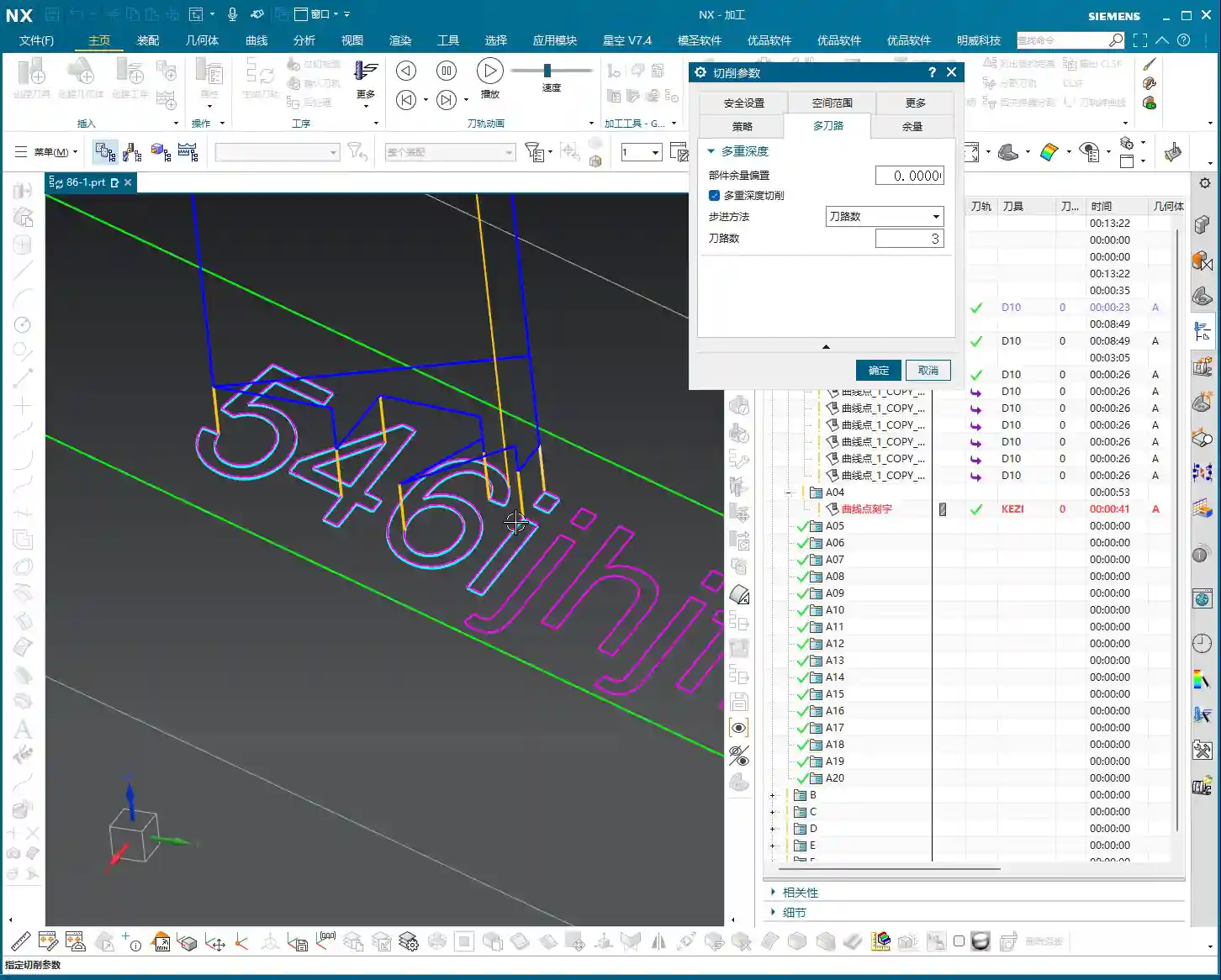
    If deeper engraving is required or the material is particularly hard, you’ll need to use “multiple passes”. This is similar to roughing: divide the machining into layers, with a smaller **Depth of Cut (DOC)** each time, which both protects the tool and ensures machining quality.

    For example, to engrave to a depth of 0.3mm (approx. 0.012 inch), set 3 passes, so each pass will have a **Depth of Cut (DOC)** of 0.1mm (approx. 0.004 inch). This ensures even tool load and smoother chip evacuation. Especially when machining challenging materials like titanium alloys or high-temperature nickel-based superalloys, multiple passes are absolutely essential. Remember, **finishing passes** are never a one-shot deal; you must proceed cautiously and steadily to produce quality parts, extend tool life, and save costs.

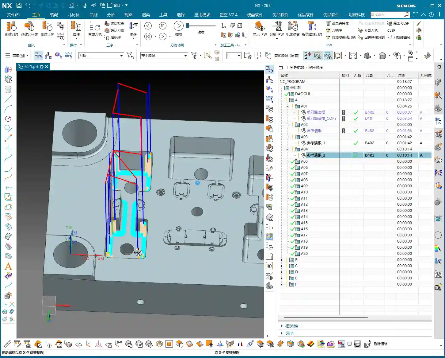
    Deeper Understanding: Projection Vector and Multi-Axis Correlation

    Here’s a quick note: this function also involves the concept of the “Projection Vector”. While we don’t often directly manipulate it in 3-axis machining, it’s a technology closely related to multi-axis machining, especially **4-axis and 5-axis programming**.

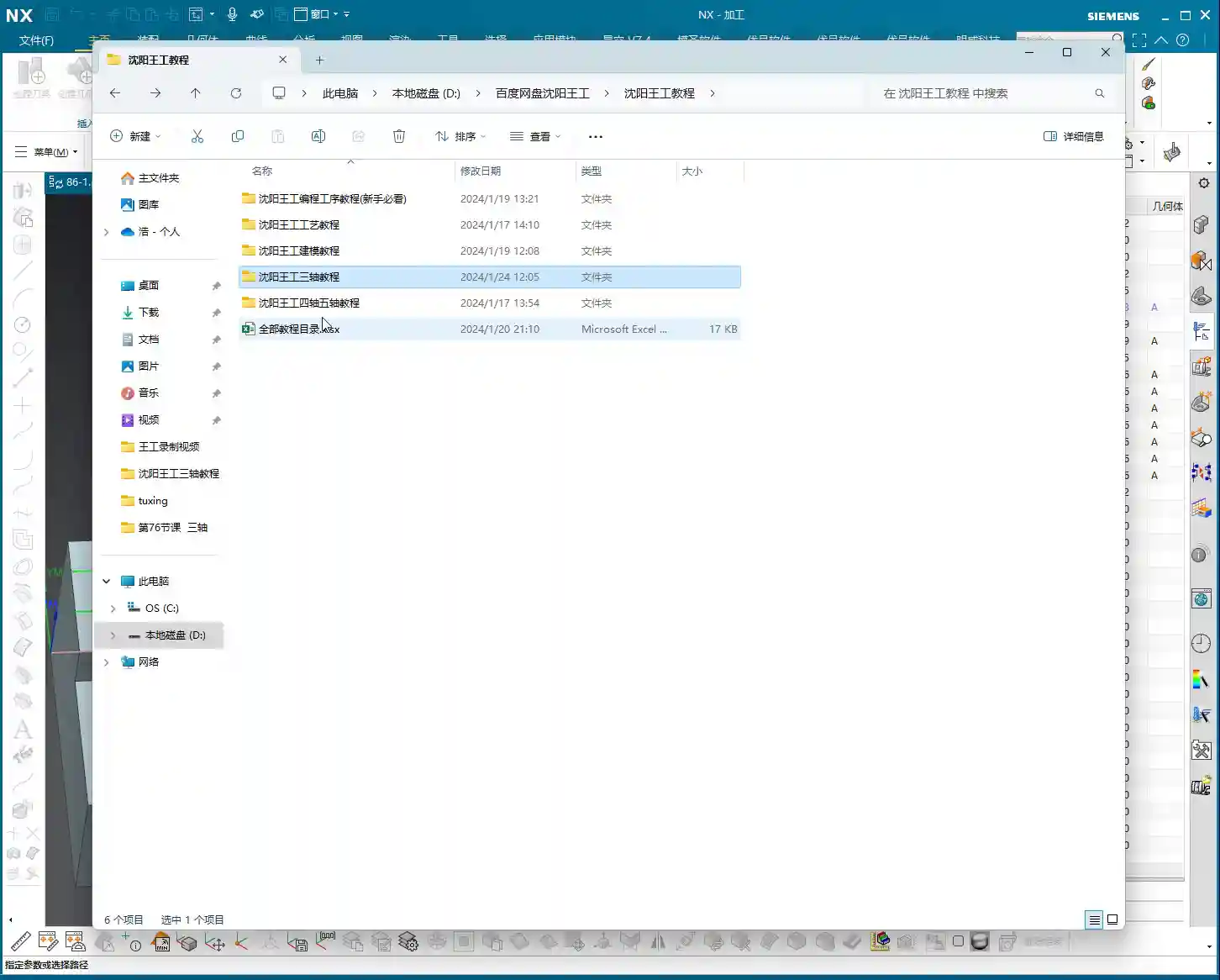
    Its purpose is to define the direction from which the tool “sees” your curve, and then “projects” that curve onto the machining face. If you want to delve deeper into this, you can refer to the section on “Fixed Axis Surface Drive Application and Projection Vector Explanation” in my previous “4-Axis and 5-Axis Programming” course, typically found in the second or third lesson. Learning more never hurts; more skills mean more opportunities! While it’s used less frequently in 3-axis, understanding it will give you a clearer insight into how toolpaths are generated on complex surfaces, which helps you optimize toolpaths, reduce air cuts, and improve efficiency.

    Summary: Pitfall Avoidance Guide

    Pitfall Avoidance Guide

    • Pitfall One: Selecting only the curve, not the face. The software will get confused! NX needs a clear “stage” to perform on, so always specify the machining face first. This is fundamental logic.
    • Pitfall Two: Ignoring “negative stock.” Think engraving is just scratching the surface? That’s “tracing a line,” not “engraving!” Understand and properly set negative stock to ensure engraving depth. Different materials and hardness levels may require fine adjustments to the negative stock.
    • Pitfall Three: Trying to cut everything in one go. For deep engraving or hard materials, don’t expect to finish in a single pass. Utilize multiple passes to protect your tools and improve surface quality. Don’t try to save a minute or two only to break a tool; the cost of repairing parts and replacing tools will be much greater.
    • Pitfall Four: Approaching a 3D function with only 2D thinking. This “Point-on-Curve Engraving” feature was born for complex 3D surfaces. Treat it as an enhanced version of planar profile milling; once you shift your mindset, a whole new world opens up! This function is a critical step in boosting your ability to machine complex parts.

    Alright, that’s all for today. Within NX’s Fixed Contour Milling, whether it’s Point-on-Curve, Boundary, Flowline, or Surface Drive, their core principles are interconnected. Observe more, practice more, think more, and you too can become a highly capable expert in the shop! Don’t just bury your head in programming; get down to the shop floor and observe the actual cutting conditions – *that’s* where true skill is forged!

    👤 About the Author:
    The author is a veteran CNC machining professional with 15 years of industry experience, specializing in UG NX programming. This article is an original work representing personal practical insights.

    ⚠️ Copyright Notice: Unauthorized reproduction or distribution without prior communication is strictly prohibited.

  • Multi-Pass Corner Cleanup in Siemens NX: In-Depth Analysis of Precise Stock Control and Efficiency S

    📝 Key Takeaways: Master Wang explains Multi-Pass Corner Cleanup in Siemens NX, emphasizing its interface similarity to Single-Pass and Reference Tool Corner Cleanup, but highlighting the core feature of “Number of Passes per Side” for precise stock control. He points out the necessity of manually calculating remaining stock, integrating material properties, optimizing toolpaths to achieve ±0.005mm precision, stressing the importance of observing cutting sparks and chips during actual operations, and advocating mastering Reference Tool Corner Cleanup to apply knowledge across different methods.

    Alright, guys, today Master Wang is going to show you this often-overlooked feature in Siemens NX: Multi-Pass Corner Cleanup. Don’t let its similar interface to the Single-Pass and Reference Tool Corner Cleanup operations we’ve discussed fool you; there’s a lot more to it. Especially when you’re working on parts with extremely high demands for precision and surface finish, or when tackling tough, hard materials, Multi-Pass Corner Cleanup becomes your ultimate weapon for boosting efficiency, controlling stock, and ensuring accuracy!

    Listen up: in this machining game, you can’t just rely on fancy software simulations. What truly matters are the cutting sparks and chips flying off the machine. Every parameter setting must revolve around actual machining results, tool life, and cost efficiency.

    Core Logic and Characteristics of Multi-Pass Corner Cleanup

    Similarities and Differences with Single-Pass and Reference Tool Corner Cleanup

    First, let’s get this straight: from an operational interface perspective, Multi-Pass Corner Cleanup is indeed very similar to Single-Pass and Reference Tool Corner Cleanup. You still select the part, choose the blank, define the cutting region, and select the tool – these basic steps are all the same. However, its key difference lies in its ability to provide you with more precise stock control, especially when you need to gradually clean up the remaining stock at the bottom of cavities and grooves with multiple passes and small Stepover.

    It’s in the ‘Edit’ option within ‘Method’ where you’ll find some distinct differences. This is where the essence of Multi-Pass Corner Cleanup lies.

    Key Parameters: “Stepover” and “Number of Passes per Side”

    Here, we need to focus on two parameters: one is the standard “Stepover”, and the other is the ‘Multi-Pass Corner Cleanup’-specific “Number of Passes per Side”.

    Everyone is familiar with “Stepover”; it’s the lateral distance the tool feeds for each pass. If you set it to 0.5mm, the tool cuts one pass, then shifts 0.5mm laterally for the next. Nothing new there.

    The crucial part is this “Number of Passes per Side”. For example, if your default toolpath makes a pass in the middle – let’s temporarily “not count” that middle pass. Then, if you set “Number of Passes per Side” to 5, it will generate an additional 5 passes on each side of the central toolpath, forming a total of 11 passes (5+1+5). If you change it to 10, it will offset 10 passes on each side, for a total of 21 passes.

    What’s the point of this? Think about it: when machining deep cavities, narrow grooves, or high-hardness materials, you can’t expect one tool to hog it all out in a single pass. That’ll lead to chipped tools, Chatter, and quickly wear out your cutters. By adjusting “Number of Passes per Side” and “Stepover”, we can use small Depth of Cut (DOC) and small Stepover to gradually remove the remaining stock at the root, layer by layer, in controlled increments. It’s like peeling an onion, layer by layer. This not only protects your tools but also ensures machining stability and accuracy.

    Listen up, this is where real-world experience comes into play. How do you determine this “Number of Passes per Side”? You have to estimate or measure the remaining stock on your workpiece yourself. For instance, if you’ve done your Roughing with a larger tool and there’s still 1.5mm of stock left at the bottom of the groove, and your current Corner Cleanup tool has a maximum safe Stepover of 0.2mm. Then 1.5mm / 0.2mm = 7.5. You’ll need to set “Number of Passes per Side” to at least 8, or even 9 or 10, to ensure the stock is completely removed and there’s enough overlap to guarantee surface quality. This calculation isn’t something you’ll learn from a textbook; it’s accumulated through experience and understanding of material properties.

    Cutting Patterns and Toolpath Optimization

    Available Cutting Patterns

    Multi-Pass Corner Cleanup offers fewer cutting patterns, mainly Zig, Zigzag, and Mixed. These are the same as what we’ve covered in other machining operations, so Master Wang won’t go into excessive detail. Generally, for efficiency, we often use Zigzag. However, for Finishing passes or when uniform tool load is critical, Zig might be more suitable, even if it results in more unproductive rapid moves.

    • Zig: The tool always cuts in one direction, with the return path being an idle move. Advantage: stable cutting, less prone to chatter marks. Disadvantage: more unproductive moves, lower efficiency.
    • Zigzag: The tool cuts in both directions. Advantage: high efficiency, fewer unproductive moves. Disadvantage: requires higher tool strength and machine rigidity, and may produce slight marks during reverse cutting.
    • Mixed: Combines the characteristics of Zig and Zigzag, typically used to optimize cutting in specific areas.

    Inward/Outward Direction and Cutting Sequence

    Within “Cutting Patterns”, you also have “Outside-In”, “Inside-Out”, and “Lead First” and “Trail First”. These control where the tool starts and where it moves.

    • Outside-In: Gradually cuts from the workpiece exterior towards the interior, which aids chip evacuation and reduces secondary cutting. This is suitable for complex cavities or softer materials.
    • Inside-Out: Cuts from the workpiece interior towards the exterior, suitable for structures with central holes or bosses. This helps prevent chips from being trapped internally during the initial stages of machining.
    • Lead First and Trail First: These two methods, combined with Alternate, control the tool’s entry and exit sequence along the path. They are widely used, especially during Corner Cleanup, where tool and workpiece interference must be considered.

    Most of the time, to ensure even tool load and smooth chip evacuation, combinations like Outside-In Alternate and Lead First/Trail First are commonly used. The specific choice depends on your workpiece geometry, material properties, and the required surface finish. For instance, when machining difficult-to-cut materials like titanium alloys, stable cutting conditions are critical to prevent built-up edge; in such cases, the selection of cutting pattern becomes even more meticulous.

    Practical Application and Precision Control

    Material Properties and Toolpath Strategies

    Different materials require vastly different machining strategies.

    • Standard Aluminum: Excellent machinability, allowing for increased feed rates and Depth of Cut (DOC). However, be mindful of burrs during Corner Cleanup.
    • Stainless Steel, Titanium Alloys: For these difficult-to-machine materials, Corner Cleanup requires extreme caution. Tools wear quickly and work hardening is common. Here, Multi-Pass Corner Cleanup’s small Stepover, multi-layer cutting approach becomes especially critical. Combine this with appropriate coolant and tool coatings to ensure tool life and machining quality.
    • High-Temperature Nickel-Based Alloys: These are truly the “tough nuts to crack” in machining. For Corner Cleanup, you must employ a strategy of constant cutting force and stable Depth of Cut (DOC). Multi-Pass Corner Cleanup helps you precisely control the Depth of Cut (DOC) for each pass, preventing overload and Chatter, which is also beneficial for preventing heat treatment deformation.

    Achieving ±0.005mm Level Precision Control

    If your job demands precision of ±0.005mm or even tighter, then “Multi-Pass Corner Cleanup” combined with your precise calculation of remaining stock becomes absolutely critical. You must know exactly how much stock each pass leaves and how much the next pass needs to remove. This isn’t just about setting software parameters; it’s a comprehensive consideration of machine performance, tool runout, and fixture rigidity.

    Master Wang’s got a practical tip for you: before machining critical dimensions, first use a dial indicator to measure the actual remaining stock. Then, based on your final Finishing pass tool’s cutting capability, work backward to determine your “Stepover” and “Number of Passes per Side”. If your machine has accuracy errors, like 0.01mm of backlash, you might even need to apply a negative compensation in Siemens NX using the “Part Stock” or “Check Geometry”‘s “Compensation” function to “eat up” that error. That’s the real error slayer!

    Toolpath Optimization from an NX Expert’s Perspective

    As an NX expert, I’m telling you, optimizing toolpaths isn’t just about minimizing unproductive moves or finding shortcuts. For Multi-Pass Corner Cleanup, it’s even more crucial to consider tool entry/exit methods, linking moves, and the number of retracts.

    • Avoid abrupt engagements and retracts: Especially in small-area machining like Corner Cleanup, sudden tool acceleration or deceleration can easily cause Chatter or degrade surface quality. Always use arc transitions.
    • Minimize retracts: More retracts mean lower efficiency, and each time the tool retracts and re-engages, it can leave marks on the surface. If you can avoid retracting, do it; if you can reduce them, do that.
    • Consider tool wear: For materials like titanium alloys, tool wear is constant. By wisely allocating “Number of Passes per Side” and “Stepover”, you can extend the effective machining time of a single tool and reduce tool change frequency.

    Summary: Pitfall Avoidance Guide

    Alright, after all that, the core idea behind Multi-Pass Corner Cleanup is to give you more precise control over the Depth of Cut (DOC) for each pass, instead of letting the software blindly guess for you. So, remember these “pitfall avoidance guidelines”:

    1. Don’t blindly trust default parameters: Especially for “Number of Passes per Side” and “Stepover”, you absolutely must manually calculate and adjust them based on the actual remaining stock, material, tool, and precision requirements of the workpiece. If you set them without knowing what you’re doing, the part will either lack precision or you’ll scrap your tool.
    2. Thoroughly understand material properties: The Depth of Cut (DOC) for soft materials is completely different from hard materials. If you don’t understand material characteristics, even the best toolpath strategy is useless.
    3. Pay attention to cutting sparks and chips: Software simulations are static; machine operations are dynamic. During cutting, observe the spark color, chip shape, and sound. Excessive sparks, blue chips, or abnormal noises all indicate issues with your parameters; stop and adjust.
    4. Prioritize mastering “Reference Tool Corner Cleanup”: Why? Because “Reference Tool Corner Cleanup” has the most comprehensive parameters; it’s the “big brother” of these three Corner Cleanup operations (Single-Pass, Multi-Pass, Reference Tool). If you master the big brother, many of its logics and parameter settings are universal and applicable to Multi-Pass and Single-Pass, which have fewer, simpler parameters. Master the big brother, and the younger siblings will be easy to handle.
    5. Practice more, think more, summarize more: No one is born a master craftsman; everyone gets there through continuous practice and hands-on experience. After every machining job, you must summarize your lessons learned. That’s how you truly turn these tricks into your own expertise!

    That’s all for today. Go on and think this through on your own. Remember, in machining, there are no shortcuts. Only by being grounded and knowing your stuff can you become a true expert! See you next time!

    👤 About the Author:
    The author is a veteran CNC machining professional with 15 years of industry experience, specializing in UG NX programming. This article is an original work representing personal practical insights.

    ⚠️ Copyright Notice: Unauthorized reproduction or distribution without prior communication is strictly prohibited.

  • In-Depth Analysis of Corner Cleanup in Steep Regions with Siemens NX: Master Wang’s Hands-on Guide t

    📝 Key Takeaways: Master Wang provides hands-on techniques for Corner Cleanup in steep regions using Siemens NX. This in-depth analysis covers the pros and cons and application scenarios of One-Way and Zigzag machining modes, emphasizing the importance of Depth Machining and smooth toolpaths. It will help you optimize your toolpaths, improve machining efficiency and part quality, and avoid pitfalls not found in textbooks.

    Hello everyone, Master Wang here! Today, we’re skipping the fancy theories and getting straight to the point. The job in front of us is a classic case of Corner Cleanup in steep regions – these areas are notorious for issues and truly test your skills. Listen up, because today we’re going to thoroughly discuss the ins and outs of Corner Cleanup and different machining modes.

    Default Zigzag Machining: What’s the Problem?

    First, let’s do a standard operation. Pick any tool, select the area for Corner Cleanup, and generate a program. Watch closely, I’ll select the region faces to be cleaned. Right-click, select Tangent Faces – you’re all familiar with that.

    Observing the Default Toolpath: Drawbacks of Zigzag Machining

    Now, I’ll run this with the default Zigzag machining mode. Since there are many faces, the calculation might take a bit – don’t rush it.

    See that? As soon as the toolpath is generated, the problem becomes obvious. In these steep regions, the tool cuts back and forth, leading to uneven cutting forces. Don’t just rely on the smooth software simulation; once you run it on the machine, you’ll find:

    • Prone to heavy cuts/Tool Dig-in: When the tool reverses direction, the cutting force changes instantaneously, often causing the tool to dig in sharply. At best, it leaves tool marks; at worst, it chips the insert or even scraps the part!
    • Poor Surface Quality: With back-and-forth cutting, especially on steep slopes, the tool can easily slip or, when reversing direction, leave unsightly “fish-scale patterns” or “pitting.”
    • Shorter Tool Life: Constantly enduring impacts and changes in direction accelerates tool wear, naturally shortening its lifespan and increasing your costs, doesn’t it?

    So, while Zigzag machining might be acceptable in flat areas, encountering Corner Cleanup in steep regions with it is practically asking for trouble.

    Preferred for Steep Regions: One-Way Machining

    For these steep Corner Cleanup regions, we need a different approach. In my experience, One-Way machining is the way to go!

    Advantages and Setup of One-Way Machining

    Alright, I’ll change this machining mode to One Way. We’ll set the depth to 0.2mm. Don’t forget, for Corner Cleanup, you need a small Depth of Cut (DOC) to ensure accuracy and surface finish. Then, regenerate the toolpath.

    See that? Now the tool moves in only one direction – for instance, cutting from top to bottom. After completing a pass, it retracts and rapids back to the start point to begin the next pass. While it appears to have more Air Cuts and might seem less efficient, the reality is:

    • High Machining Stability: The tool is consistently loaded in one direction, leading to a very stable machining process, less prone to chatter or chipping.
    • Excellent Surface Finish: One-Way machining prevents the tool from reversing direction during cutting, eliminating tool marks and imperfections caused by direction changes. This naturally results in a superior surface finish.
    • Extended Tool Life: Reducing the impact from direction changes leads to more even tool wear and significantly extends tool life.

    In steep regions, machining stability and surface quality are paramount. The minor loss from those Air Cuts is easily recuperated by improving yield and tool life. You need to crunch these numbers carefully!

    “Zigzag Upward”? You’re Asking for Trouble!

    Some of you might ask, what about Zigzag Upward or Zigzag Parallel to Tool Axis? I’m telling you, for steep regions, these modes should be used with extreme caution, or frankly, not at all!

    Look closely at such a toolpath: when it cuts upward, the tool is essentially climbing against the cutting direction, aggressively “biting” into the material. How terrible are those cutting forces? It’s highly prone to chatter, chipping, and can even scratch the part surface. Don’t just rely on software simulations; observe the cutting sparks and chips – they’ll tell you the real story.

    If you absolutely must use a zigzag approach, at least use the Perpendicular to Tool Axis mode, ensuring the tool always cuts down the material, which provides much better cutting forces. But even then, it’s still fundamentally zigzagging, and risks remain at corners.

    Master Wang’s Pro Tips: Combining Depth Machining and Smoothness

    Now, I’m going to teach you some practical tips you won’t find in textbooks.

    The Clever Application of Depth Machining

    Sometimes, relying solely on Corner Cleanup operations might not be flexible enough, especially when encountering both steep and deep Corner Cleanup regions. In such cases, I lean more towards using the Depth Machining function.

    Depth Machining itself is designed for steep walls. It offers better control over the tool’s cutting in the Z-axis direction, and when combined with One-Way machining mode, it can generate highly stable and efficient toolpaths. It handles depth more effectively, making the toolpaths appear more smooth and continuous, rather than just focusing on localized areas like simple Corner Cleanup.

    Ultimate Optimization: One-Way Machining + Smooth

    However, if you want to perfect steep regions within a Corner Cleanup operation, my ultimate secret is this: use One-Way machining mode, and then make sure to activate the Smooth function!

    Let me show you. When you combine One-Way machining with the Smooth function enabled, and then regenerate the toolpath, you’ll observe:

    • More Refined Toolpaths: What might have been subtle jumps or unevenness before now becomes incredibly smooth and flowing, as if hand-drawn.
    • Increased Machining Stability: The Smooth function optimizes tool engagements, retracts, and connection paths, reducing unnecessary sharp turns and impacts, leading to a much more stable cutting process.
    • Exceptional Surface Finish: Smooth toolpaths translate to more consistent cutting, and the part’s surface finish and texture will achieve a very high standard.

    That Smooth function isn’t just for show; it can be a real lifesaver in critical situations! Especially for parts with tight tolerances and demanding surface finish requirements, One-Way machining combined with Smooth is almost always my first choice. Try it, and you’ll see. This is veteran experience; you won’t necessarily find such detailed explanations in textbooks.

    Flexible Combinations, Context-Specific Application

    So, Corner Cleanup has its applications, and Depth Machining has its advantages. It’s not about one being definitively better than the other; the key is flexible combination and adapting to the situation. It’s like going to battle – you can’t rely on just one weapon.

    • Corner Cleanup operations: Typically used for final finishing, thoroughly cleaning out those small corners and root areas left after roughing and semi-finishing. It focuses on local details.
    • Depth Machining: Is more suitable for areas with strong overall form, significant depth, and steep slopes. It can be used as a finishing pass before Corner Cleanup, or independently for machining deep cavities and steep walls.

    In practical application, you might find that toolpaths achievable with Corner Cleanup might not be possible with Depth Machining, and vice-versa. Therefore, they are not mutually exclusive but rather complementary and work in synergy. Remember, no method is inherently good or bad; it’s about how well you apply it! Practice more, ponder more, and the machine will naturally obey your commands!

    Summary: Pitfall Avoidance Guide

    1. For Corner Cleanup in steep regions, use Zigzag machining with caution: Unless it’s a flat area, the Zigzag mode can easily lead to uneven tool loading, causing tool marks, chipping, or poor surface quality.
    2. Prioritize One-Way machining: For steep regions, the One Way mode ensures machining stability and surface finish quality. Even with more Air Cuts, it offers greater long-term benefits.
    3. Enable the Smooth function: When using One-Way machining mode, be sure to enable Smooth. This significantly optimizes toolpaths, enhancing surface quality and tool life. This small detail can save you a lot of trouble.
    4. Depth Machining is a powerful tool: For steep and deep regions, consider using Depth Machining. It offers distinct advantages when handling deep cavities and steep walls.
    5. Understand the purpose of different commands: Corner Cleanup is primarily for final finishing, cleaning tight corners. Depth Machining can be used for intermediate finishing or large steep walls. They are partners, not rivals.
    6. Practice makes perfect: No amount of theory compares to hands-on experience. Grab any model, click around, generate several toolpaths, compare them, and you’ll uncover the secrets.

    That concludes today’s lesson. I hope you can absorb and apply these practical experiences. Next time, we’ll discuss the intricacies of multi-toolpaths – that’s a whole new ballgame!

    👤 About the Author:
    The author is a veteran CNC machining professional with 15 years of industry experience, specializing in UG NX programming. This article is an original work representing personal practical insights.

    ⚠️ Copyright Notice: Unauthorized reproduction or distribution without prior communication is strictly prohibited.

  • Siemens NX Corner Cleanup (Rest Milling): Master Wang’s 15 Years of Experience – Avoid Pitfalls, Dou

    📝 Key Takeaways: Master Wang provides practical guidance on Siemens NX Corner Cleanup (Rest Milling) modes. He highlights “Zig-zag Up + Outside-in Alternating + Smooth” as the most practical and efficient combination, capable of reducing air cuts and protecting tools. He thoroughly explains the advantages, disadvantages, and application scenarios for One-way/Zig-zag Horizontal, Depth Machining, and Follow Periphery modes. Furthermore, Master Wang discusses the strategic choice between “Plunge Milling” and “Area Milling” operations and concludes with a pitfall avoidance guide, emphasizing real-world experience and cost-efficiency.

    Hello everyone, I’m Master Wang. Today, let’s talk about choosing the right Corner Cleanup (Rest Milling) modes in Siemens NX. Don’t underestimate these modes; pick the right one, and your efficiency will skyrocket, and tool life will be extended. Choose incorrectly, and you’ll either have excessive air cuts, premature tool wear, or even scrap the part entirely! Listen up, because this is practical experience I’ve gathered over 15 years, getting my hands dirty on the shop floor – you won’t find this in any textbook.

    Master Wang’s Insights: The Essence of Corner Cleanup Modes

    Apprentices, you must understand that for Corner Cleanup (Rest Milling), especially in complex cavities and surfaces, the machining sequence and toolpath direction are paramount. I’ve personally put together a highly effective and efficient combination strategy that I use most often – it’s one of my core specialties.

    The Ultimate Combination: Zig-zag Up + Outside-in Alternating + Smooth

    The most effective toolpath pattern I use, and one that consistently delivers the best results, is “Zig-zag Up,” paired with an “Outside-in Alternating” cutting sequence. Crucially, always remember to enable the “Smooth” option. Why do I emphasize this?

    • Zig-zag Up: In this mode, the tool travels up from the bottom, then down from the top, in a reciprocating motion. Unlike simple one-way cutting, which requires the tool to retract and return after each pass, Zig-zag Up effectively reduces retractions and maintains continuous cutting, making it particularly suitable for cavities with a certain draft angle.
    • Outside-in Alternating: This cutting direction is the core principle! It ensures the tool starts from the periphery of the Corner Cleanup area and gradually moves inward. This guarantees sufficient space for engagement, preventing the tool from making a full-width cut at the beginning. It significantly reduces the risk of excessive Depth of Cut (DOC) and chipping. Especially for harder materials like titanium alloys and high-temperature nickel-based superalloys, this cutting method effectively protects the tool and extends its life.
    • Smooth: This option is extremely important, yet often overlooked. Enabling “Smooth” makes the toolpath very fluid, eliminating sharp turns and acute angles, which reduces machine shock and vibration. Sometimes, if you notice the tool “jumping” (the tool suddenly lifts and drops, which is very damaging), it’s likely because your Stepover setting for “Smooth” is too small. A smaller Stepover can be counterproductive due to frequent tool retractions. I typically adjust the Stepover based on tool diameter and material; for example, when performing corner cleanup with a ball end mill, a Stepover of 5%-10% of the tool diameter is usually sufficient, but always observe the cutting sparks and sound in real-time.

    This combination strategy ensures the tool maintains a relatively stable cutting load during Corner Cleanup (Rest Milling), resulting in smooth toolpaths, high machining efficiency, and improved part surface quality. Don’t just rely on software simulations; during actual cutting, you need to observe the sparks at the cutting edge and listen to the cutting sound – that’s where true skill lies.

    Detailed Explanation of Common Corner Cleanup Modes

    One-way Horizontal

    As the name suggests, this mode involves unidirectional, horizontal tool movement. After completing a pass, the tool retracts to the start point before beginning the next. This method might be suitable for simple flat areas or shallow groove Corner Cleanup, but it’s generally inefficient due to excessive time spent on air cuts and retractions. If you use this in complex cavities, your machining time will be simply wasted on tool retractions.

    Of course, if you enable the “Smooth” option, the toolpath can become spiral-like, cutting downwards in circles, which looks much cleaner and can achieve some Corner Cleanup effect. However, overall, it’s less efficient and flexible than the “Zig-zag Up” mode.

    Zig-zag Horizontal

    This is an upgraded version of One-way Horizontal, where the tool cuts back and forth with no tool retraction in the Z-axis direction, reducing idle travel. It steps down one layer, then cuts horizontally in a reciprocating motion. This can be considered for cleaning the root areas of square or rectangular features. However, for complex Corner Cleanup regions or those with draft angles, this mode is less adaptable than “Zig-zag Up.”

    Zig-zag Up Horizontal

    This mode is quite similar to “Zig-zag Up,” but it emphasizes horizontal reciprocating cuts followed by a Z-axis ascent. Compared to my “Zig-zag Up + Smooth” combination strategy, if “Smooth” is not enabled, it might produce a more noticeable stepped appearance in the Z-axis direction, and toolpath transitions won’t be as smooth. Therefore, even when using this mode, I usually enable “Smooth” to ensure more fluid tool movement.

    Considerations for Depth Machining Modes

    In Siemens NX, some modes have “Depth” in their names, which sounds impressive-sounding, but their practical application depends on your workpiece characteristics and machining requirements.

    One-way Depth Machining

    This mode involves unidirectional vertical plunging, with the tool retracting and returning after each cut. If you want to perform stepped deep cuts at a specific point or area, this could be considered. However, it’s rarely used alone for general Corner Cleanup due to its inefficiency. Personally, if I were to do something like this, I’d opt for helical plunge milling instead, which is more direct and ensures more uniform tool engagement.

    Zig-zag Depth Machining

    Similar to One-way Depth Machining, except the tool can perform reciprocating plunging. Again, these depth machining modes are typically not the first choice for Corner Cleanup, unless you are specifically cleaning the bottom of blind holes or deep, narrow slots. In most complex cavity Corner Cleanup scenarios, their efficiency and tool life protection are not ideal.

    Special Mode: Follow Periphery

    Follow Periphery

    This mode is also very useful. It enables the tool to follow the contour of the Corner Cleanup area, progressing inward or outward layer by layer. For regularly shaped Corner Cleanup regions, especially those with well-defined boundaries, it can generate very clean toolpaths. However, there’s a point to note: how does it determine “inward” versus “outward” cutting? This requires you to have a clear understanding of the model boundaries and desired toolpath. If it feels awkward to use, or you’re unsure if its cutting direction is what you want, then just stick to Zig-zag Up – it’s generally more reliable.

    The Philosophy of Mode Selection: “Plunge Milling” vs. “Area Milling”

    In Siemens NX, you might sometimes notice that the cutting mode options within “Area Mill/Contour Area” and “Plunge Mill/Contour Profile” operation types look similar. However, you must understand that their application scenarios are different.

    • “Area Mill/Contour Area”: This is typically used for machining an overall area or surface. It’s based on a plane or region, where the tool cuts horizontally and then steps down layer by layer. The modes we discussed earlier, such as Zig-zag Up, Zig-zag Horizontal, and Follow Periphery, are most commonly used here, primarily to cover the entire Corner Cleanup region.
    • “Plunge Mill/Contour Profile”: The name itself implies a focus on depth-oriented machining. For instance, if you need to mill a deep hole or clean the bottom of a deep, narrow slot, you would likely use modes within the “Plunge Mill” operation type, as it emphasizes the tool’s plunging strategy in the Z-axis direction.

    Therefore, when selecting a mode, you must first determine your primary objective: do you want to efficiently clear an area (select the appropriate mode under “Area Mill” operations), or do you want to more effectively handle depth-oriented cutting (select the appropriate mode under “Plunge Mill” operations)? Generally speaking, for Corner Cleanup, most of the time, we’re selecting within “Area Mill.” Remember what I said: Zig-zag Up, Outside-in Alternating, and with Smooth enabled – these three are your powerful tools within “Area Mill.”

    Summary: Pitfall Avoidance Guide

    1. Mode selection must align with the workpiece: There’s no one-size-fits-all mode. The shape, depth, and material hardness of the Corner Cleanup region all influence your choice. Don’t just blindly apply them.
    2. Effectively utilize the “Smooth” function: It makes toolpaths smoother, reduces machine shock, protects the tool, and improves surface quality. However, the Stepover setting must be reasonable; too small will lead to frequent retractions.
    3. Beware of “Tool Jump”: When the tool suddenly lifts and drops during machining, it’s often caused by unreasonable toolpath settings, too small a Stepover, or sudden changes in cutting angle. This can cause chipping and even damage the workpiece.
    4. Machining sequence is crucial: Outside-in cutting is generally safer and effectively prevents “excessive Depth of Cut (DOC).”
    5. Don’t solely trust software simulations: Simulations are just theoretical. In actual machining, tool wear, machine accuracy, and fixture rigidity all influence the outcome. Observe cutting sparks and listen to the sound – that’s the machine “talking” to you.
    6. Prioritize cost efficiency: Every programming task must consider tool costs and machining time. Avoiding unnecessary idle travel and optimizing toolpaths are fundamental skills for every good engineer.

    Alright, that’s all for today. Go back, practice more, think more, and next time we’ll discuss other practical tips. See you!

    [EXCERPT]
    Master Wang provides practical guidance on Siemens NX Corner Cleanup (Rest Milling) modes. He highlights “Zig-zag Up + Outside-in Alternating + Smooth” as the most practical and efficient combination, capable of reducing air cuts and protecting tools. He thoroughly explains the advantages, disadvantages, and application scenarios for One-way/Zig-zag Horizontal, Depth Machining, and Follow Periphery modes. Furthermore, Master Wang discusses the strategic choice between “Plunge Milling” and “Area Milling” operations and concludes with a pitfall avoidance guide, emphasizing real-world experience and cost-efficiency.

    👤 About the Author:
    The author is a veteran CNC machining professional with 15 years of industry experience, specializing in UG NX programming. This article is an original work representing personal practical insights.

    ⚠️ Copyright Notice: Unauthorized reproduction or distribution without prior communication is strictly prohibited.

  • Siemens NX Finishing Toolpath Optimization: Master Wang’s Practical Insights Unveiled for Steep Firs

    📝 Key Takeaways: In-Depth Analysis of Siemens NX Finishing Toolpath Strategies Hello everyone, this is Old Wang, or you can call me Master Wang. Today, we…

    Hello everyone, this is Old Wang, or you can call me Master Wang. Today, we’re cutting the fluff and getting straight to the practical insights. In Siemens NX, finishing toolpath strategies are countless, but which ones genuinely deliver results and which are just flashy but useless? Listen up! Today, I’m going to clarify the practical experience I’ve accumulated over the years, especially regarding the nuances of “Steep First,” “Shallow First,” and “Alternating” machining.

    Reciprocal Machining Mode: Efficiency First

    In NX programming, when clearing residual material or performing large-area finish cuts, we encounter “One-Way” and “Reciprocal” modes. Don’t hesitate, Reciprocal mode is the preferred choice in most cases. Why? Because it maximizes tool utilization, reduces rapid moves (idle time), and boosts efficiency.

    Why Reciprocal Mode is Commonly Used

    In NX machining operations, such as roughing for corner cleanup or large-area face milling and surface milling, if Reciprocal mode can be used, I almost always use it. The tool makes a pass, cutting material; on the return pass, it continues cutting. Unlike One-Way, where it cuts on one pass and the return is a rapid move, wasting precious time. In our line of work, every second counts. Saving one rapid move, multiplied over time, translates to profit. That’s why Reciprocal mode is used far more than One-Way for material removal and finishing. This should be self-evident.

    Steep Area Strategies: Steep First vs. Shallow First in Practice

    Next up are the “Steep First” and “Shallow First” strategies. These are settings in NX for the machining order of steep and shallow areas on a workpiece. Sounds simple, but if used incorrectly, it can severely reduce tool life, lead to tool breakage, or scrap parts. This is serious business!

    Steep First Strategy: Tackling Steep Surfaces

    The “Steep Area First” strategy, as the name implies, means prioritizing machining of areas with a significant slope (e.g., steep surfaces exceeding 30-45 degrees), and then addressing the shallower areas. In practical application, if your workpiece primarily features curved surfaces with noticeable slopes, especially those where steep faces make up a larger proportion, using the “Steep First” strategy is often more effective. It allows the tool to tackle the most challenging “hard spots” first under stable cutting conditions, reducing vibration and tool wear in subsequent operations.

    Remember, don’t just look at how nice the simulation in NX looks. Focus on the actual cutting sparks and sound from the machine. If the sparks are consistent and the sound is uniform, your toolpath is fine. If the sparks fluctuate wildly or the sound is occasionally harsh, chances are your strategy is wrong, or your parameters aren’t tuned correctly.

    Shallow First Strategy: Processing Shallow Surfaces

    The “Shallow Area First” strategy, also known as “Non-Steep Area First” or “Flat Area First,” processes the shallow areas of the workpiece first, then the steep areas. When is this strategy useful? Let me give you an example: if the workpiece is a cavity with straight, vertical walls or similar features, choosing “Shallow First” is generally better. Why? It starts machining from the bottom or shallow areas, ensuring the initial cut is stable, and then proceeds layer by layer upwards (or outwards). This is like a dynamic cutting process where material removal for each layer is quite uniform, preventing the tool from initially “plowing” into excessively thick material. This consistent chip load is especially critical for tool life when machining challenging materials like titanium alloys or high-temperature nickel-based alloys.

    Which one to use isn’t absolute; it depends on your part’s geometric features. There’s no single best strategy, only the most suitable one. This is practical experience; you won’t always find such detailed explanations in textbooks.

    Alternating Machining Strategies: The Nuances of Out-to-In vs. In-to-Out

    The “Out-to-In Alternating” and “In-to-Out Alternating” strategies in NX play a crucial role in finishing, especially during Corner Cleanup. These two strategies primarily control the tool’s machining sequence within the cutting area: whether it starts from the periphery and “peels” inwards layer by layer, or starts from the interior and “expands” outwards layer by layer.

    Out-to-In Alternating: The Corner Cleanup Ace

    The “Out-to-In Alternating” strategy – I’ll say it – is absolutely one of the most commonly used and effective strategies for our corner cleanup operations! It initiates the cut from the outermost edge of the workpiece’s machining area, then progressively cuts inward, while alternating during the process. What does this mean? It makes one cut on the outermost path, then jumps to a slightly inner position for another cut, then jumps back, and so on, moving further inward. The benefits of this machining approach are:

    1. Uniform Chip Load: The tool removes a very consistent amount of material with each cut, avoiding sudden heavy or light loads. This is exceptionally beneficial for maintaining tool stability and extending tool life.
    2. Excellent Surface Quality: Due to the smooth cutting process and uniform material removal, the resulting surface quality is particularly good, less prone to tool marks or chatter marks.
    3. Thorough Corner Cleanup: It can gradually and completely remove residual material from the corners, leaving no hard spots.

    I use this “Out-to-In Alternating” strategy for about seventy to eighty percent of my finishing passes, especially for mold corner cleanup. Its uniform toolpath distribution and consistent material removal are the gold standard in our actual production.

    In-to-Out Alternating: Use with Caution

    The “In-to-Out Alternating” strategy, on the other hand, starts cutting from the interior of the machining area and gradually expands outwards. I use this strategy relatively rarely; in fact, I’d say it’s not recommended for most finishing corner cleanup scenarios.

    Imagine if there’s residual material at the bottom of a cavity, and your initial cut starts from the innermost point and expands outwards. That first cut could very likely engage a significant amount of material, leading to an instantaneous heavy chip load. As I said in my audio earlier, “the very first cut finishes the entire corner of our part”, which indicates the tool is subjected to immense impact, potentially causing tool breakage, chatter, or even scrapping the part. Of course, this doesn’t mean it’s entirely useless. In certain special part geometries or specific process requirements, it might occasionally come in handy. But in production, we prioritize stability and reliability. So, if you’re unsure about this strategy, try to avoid it if possible, or at least run multiple simulations to check if the chip load and toolpath are reasonable. Don’t just rely on software simulations; pay attention to cutting sparks and cutting forces!

    Summary: Pitfall Avoidance Guide

    Listen up, junior engineers, everything I’ve shared today is hard-earned experience. I hope it helps you avoid common pitfalls:

    1. Prioritize Reciprocal Mode: Whenever conditions allow, use reciprocal mode for finishing and large-area machining. Saving rapid moves means saving money.
    2. Steep First and Shallow First: Be Flexible: There’s no one-size-fits-all. For workpieces with overall significant slopes, consider “Steep First.” For workpieces with vertical walls or similar straight-up-and-down features, “Shallow First” is often more stable. You need to analyze how your tool will dynamically engage the material to ensure stable cutting.
    3. “Out-to-In Alternating” is the Ace for Finishing Corner Cleanup: It’s virtually applicable to all situations requiring precise corner cleanup. It ensures uniform cutting, improving surface quality and tool life. I personally highly recommend it, and it’s my most frequently used strategy.
    4. Use “In-to-Out Alternating” with Caution: Unless you have a very clear justification and thorough verification, this strategy can easily lead to excessive chip load on the initial cut in finishing, causing problems. Newcomers should especially avoid it.
    5. Don’t Blindly Trust Software Simulations: Software is static; machines and materials are dynamic. The ultimate judgment criteria are the actual machine’s cutting sound, sparks, tool wear, and the final part accuracy and surface quality. Listen more, watch more, feel more – these “unwritten” practical tips are your real assets.

    Our profession is all about experience. Practice more, think more, and summarize your findings. Ponder these toolpath strategies carefully, and they will help you navigate NX programming with fewer headaches and produce more high-quality parts.

    👤 About the Author:
    The author is a veteran CNC machining professional with 15 years of industry experience, specializing in UG NX programming. This article is an original work representing personal practical insights.

    ⚠️ Copyright Notice: Unauthorized reproduction or distribution without prior communication is strictly prohibited.

  • Practical Analysis of Single-Pass Corner Cleanup in Siemens NX: Master Wang’s Guide to Precise and E

    📝 Key Takeaways: ** Master Wang provides a hands-on guide to practical techniques for single-pass Corner Cleanup in Siemens NX. This focuses on understanding the logic behind simplified parameters, distinguishing between highlighted regions and actual toolpaths, avoiding common pitfalls of relying solely on software simulations, and ensuring efficient and precise Corner Cleanup. **

    Hello everyone, I’m Master Wang. Today, let’s continue discussing practical applications. As far as the previous “Main Region” discussions go, I believe we’ve covered everything, mainly area management and some fundamental considerations. Now, let’s jump straight to the core topic: Single-Pass Corner Cleanup.

    Single-Pass Corner Cleanup in NX: Fundamental Concepts and Key Parameters

    Command Overview and Application Scenarios

    Listen up, this Single-Pass Corner Cleanup, as the name implies, is about using one tool for one pass to clean out the material left behind in corners that larger tools couldn’t reach. Often, after roughing with a large tool, there’s always some residual material in the corners. That’s when you need a smaller tool for Corner Cleanup. This command is specifically designed for that job.

    Parameters like ‘Angle,’ ‘Minimum Cut Length,’ and ‘Merge Distance’ have been thoroughly explained when I covered deep slot Contour Milling and Surface Milling. We won’t delve into them again here. If you don’t remember, go back and review your previous notes. These are fundamental skills you can’t afford to forget.

    Cutting Strategies for Steep and Non-Steep Regions

    Let’s go straight to the ‘Steep Area Angle’ parameter; this is crucial. For example, if it’s set to 65 degrees. What does this mean? It means that when the workpiece’s sloped surface angle is less than 65 degrees, it will not machine it; toolpaths will only be generated for Corner Cleanup in steep areas that are greater than or equal to 65 degrees. This follows the same logic as our previous discussion on defining ‘steep’ and ‘non-steep’ regions in Surface Milling.

    As for cutting methods in ‘non-steep regions,’ such as ‘One Way,’ ‘Climb,’ ‘Conventional,’ or ‘Mixed,’ you should all be clear on those by now, so I won’t belabor the point.

    Specificity of Single-Pass Corner Cleanup

    I need to emphasize something here: because it’s ‘Single-Pass’ Corner Cleanup, as the name suggests, it only makes one pass. Therefore, for many parameters, such as cutting direction, simply selecting ‘One Way’ is sufficient. It’s not like other complex milling strategies that present you with a plethora of options. In this operation, fewer options actually make it simpler; you don’t need to overthink it. Similarly, for steep region cutting strategies, ‘One Way’ or ‘Same as Non-Steep’ is often enough, or even ‘None’ will work, because it’s just one pass; there aren’t many fancy variations.

    Master Wang tells you, for this command, relatively few parameters need modification; most of the time, the defaults are fine. Because its core purpose is: one cleanup pass! To remove the residual material from those corners.

    In-depth Analysis: The Nuances of Multi-Pass Processing in Single-Pass Corner Cleanup

    Practical Interpretation of Multi-Pass Processing

    Although it’s called ‘Single-Pass Corner Cleanup,’ it also includes a ‘multi-pass’ option. You might ask, isn’t that contradictory? Listen closely, this is where some ‘book-smart’ knowledge won’t cut it.

    For example, if you’ve set up multi-passes with a total stock of 10 mm and a Depth of Cut (DOC) of 1 mm per pass. How will it proceed? It won’t simply cut layer by layer in the Z-axis direction like conventional machining. Instead, it will generate multiple passes that spread outward in an arc shape, based on the geometry of the corner you are cleaning up. This means if your corner has a radius, it will follow that radius, expanding outward with each successive pass, not just extending in the Z-direction. Don’t be fooled by the simulated toolpaths in the software and think it’s like regular Z-level machining; you’d be mistaken!

    This approach is designed to better clean irregular or filleted residual areas, allowing the tool to conform more closely to the workpiece shape during cleanup. So, don’t be surprised when you see the toolpath expand in concentric arcs; it’s precisely extending the Corner Cleanup outward according to your fillet geometry.

    Misconception Warning: Yellow Trajectory ≠ Actual Toolpath

    Select an area and generate the program, and you’ll see a bunch of yellow trajectory lines. Many new apprentices, seeing all this yellow on the screen, immediately assume it’s all toolpath. Big mistake! Listen up, this is a major pitfall.

    Those yellow lines are merely areas that the software has highlighted as ‘potential toolpath generation’ regions, or rather, the reachable range for the tool. However, the true toolpath is only counted where the tool actually engages and cuts material. If you replay the program, you’ll see that in some areas marked yellow, the tool never actually descended – that’s not a toolpath! It’s just telling you there might be material there, and theoretically, the tool could reach it, but in actual machining, due to unmet conditions or simply no remaining stock, it won’t generate a real cutting toolpath.

    So, don’t just look at the yellow lines from the software simulation; you need to see the cutting sparks, to confirm if the tool is truly engaging and doing work! This is practical experience; textbooks don’t always go into this much detail.

    Practical Demonstration: Tool Selection and Path Generation

    Impact of Tool Selection on Corner Cleanup Effectiveness

    Let’s try switching tools. For instance, if I use a D10 (10mm diameter) tool for Corner Cleanup. You’ll notice it also follows the contour of the selected area, making one pass. It will make a Finish cut around all qualified edges. Both the outer contour here and the small corner there will be machined. Of course, if that corner isn’t clean enough with a D10 tool, then you’ll need to switch to a smaller tool – D6, D4, or even D2, depending on the actual requirements.

    The core of this command is ‘Corner Cleanup,’ so it will try its best to clean along the contour lines. Sometimes, even if a corner has a fillet at the bottom, or no fillet at all, as long as it’s within the designated region, it will attempt to generate a toolpath. But whether it genuinely cuts material depends on the actual remaining stock and the tool size.

    Toolpath Generation and Effects of Full-Area Corner Cleanup

    If we select the entire workpiece as the Corner Cleanup region and then generate toolpaths. You’ll find that the program becomes very extensive and messy. This is because it will attempt to clean all internal contours, external contours, and every ‘corner’ it can find, using the single-pass method. The resulting toolpaths will look dense and highly complex.

    However, this also highlights its ‘Corner Cleanup’ characteristic: leaving no corner untouched. Some small grooves might appear ‘overcut,’ but that’s because the tool also makes a single pass through them. Therefore, when using this command, you must precisely select the areas requiring Corner Cleanup based on the actual situation, rather than selecting everything indiscriminately. Otherwise, efficiency will suffer, and the program will be disorganized.

    Summary: Pitfall Avoidance Guide

    1. Understand the Essence of ‘Single-Pass’: Its core principle is to make only one pass, so many complex parameters do not require extensive adjustment; prioritize simplified operation.
    2. Distinguish Between Highlighted Regions and Actual Toolpaths: The yellow paths generated in the software are merely regions where the tool is reachable or designated; they are not all actual cutting toolpaths. Always confirm through playback or simulation whether the tool is truly engaging material.
    3. Master the Multi-Pass Spreading Mechanism: When using the ‘multi-pass’ option, understand that it’s not simple Z-level layering. Instead, it cleans up by expanding outward in an arc shape based on the geometry of the Corner Cleanup region (e.g., fillets). This helps in more refined processing of complex corners.
    4. Precisely Select Corner Cleanup Regions: Avoid unnecessary full-area Corner Cleanup, as this generates a large number of redundant and disorganized toolpaths, severely impacting machining efficiency. Only select corners or residual areas that genuinely require cleanup.
    5. Combine Material and Tool Characteristics: During Corner Cleanup, thoroughly consider the material’s cutting performance and tool wear. Reasonably select feed rates and spindle speeds, and reserve appropriate machining stock. This prevents small tools from breaking or overcutting.

    Alright, that concludes our discussion on ‘Single-Pass Corner Cleanup.’ Remember, its purpose is to make one pass to clean corners; don’t overcomplicate it. Next, we’ll talk about ‘Reference Tool,’ which is much more important, and its parameters certainly warrant a more in-depth discussion.

    That’s all for today’s sharing. Thanks for watching, and I’ll see you next time!

    👤 About the Author:
    The author is a veteran CNC machining professional with 15 years of industry experience, specializing in UG NX programming. This article is an original work representing personal practical insights.

    ⚠️ Copyright Notice: Unauthorized reproduction or distribution without prior communication is strictly prohibited.

  • Siemens NX Guiding Curve Machining: Master Wang’s Hands-on Guide to Line Selection and Parameter Adj

    📝 Key Takeaways: Master Wang personally shares practical insights into Siemens NX Guiding Curve machining. A deep dive into “Deform” and “Constant Offset” strategies, teaching you how to select guide lines, adjust direction and offset, and resolve chatter and sharp corner issues. Emphasizing practicality and efficiency, comparing it with Surface Milling to help you flexibly switch based on workpiece conditions, improving machining accuracy and efficiency. No more theoretical talk.

    Hello everyone, I’m Master Wang. Today, we’re going to further explore the ins and outs of Siemens NX Guiding Curve machining. Last time, we covered some basics. This time, we’ll dive into practical examples to thoroughly explain how to use guiding lines, and how to use them smartly and effectively.

    Core Concepts and Comparison of Guiding Line Machining

    Listen up. In the machining business, rigidity is your worst enemy. Software offers countless functions, but not every one is suitable for all situations. Guiding Line machining is one of them; it has its advantages, but also its quirks. We need to understand it thoroughly.

    “Deform” vs. “Constant Offset”: Different Paths, Same Destination?

    As I’ve said before, the most common strategies in Guiding Line machining are “Deform” and “Constant Offset”. Many apprentices new to this often think they are completely different. However, for many simple planar or regular curved surfaces, the resulting toolpaths are actually quite similar.

    Let’s take a face we previously machined using “Operation B” (Area Milling) and do a comparison. I’ll directly use “Guiding Line Machining”, define the part, blank, and cut area. Then, I’ll select two boundary lines as guide lines, choose the “Deform” method, and generate the toolpath. Lo and behold, it’s virtually identical to the toolpath generated by Area Milling. This is to set the stage for you; don’t get intimidated by the terminology right from the start.

    Practical Case Study 1: Guiding Line Application for Planar Regions

    Let’s machine the first face. Right-click, insert operation, and select “Guiding Line Machining”. Define the part and blank, then comes the critical step: defining the cut area. You can’t be sloppy here; the accuracy of your selection directly impacts the toolpath’s boundaries. This time, I’ll select the entire face to be machined.

    Since we’re using “Deform”, we need two guide lines. Select two edge lines of the machining area, ensure their directions are consistent, and confirm. Once generated, you’ll see the toolpath is quite smooth, just like the previous Area Milling program.

    Next, let’s copy the operation and change the method to “Constant Offset”. Constant Offset usually only requires one guide line. I’ll select the line on the left and set the direction to “Away from Guide Line”. Generate the toolpath, and the result is again not fundamentally different from the “Deform” method. So, for regular regions, these two methods are often interchangeable, depending on your personal preference and the convenience of available lines.

    Avoiding Pitfalls: The Wisdom of Guiding Line Selection

    Now, this next case needs some serious discussion. We’re looking at an area with corners, slightly more complex, and this is where many engineers start getting confused with Guiding Line machining.

    The Root Cause of Chatter: Short Guiding Lines and Improper Direction

    I copied an operation and changed the cut area to this cornered region. Still using the “Deform” method, I selected two shorter edge lines as guide lines. After generating the toolpath and running a simulation, “Oops, chatter!” What’s more, the toolpath at the corner turns sharply, even somewhat circling. Why is this happening?

    Look closely: the guide lines themselves are short. To cover the entire cut area, the toolpath is “forced” to bend and lift. Furthermore, if the guide line direction is chosen incorrectly – for example, if it should offset to the left but you selected right – the software will stubbornly try to calculate it, resulting in a series of useless tool lifts (chatter) and irrational movements.

    Therefore, there’s a crucial prerequisite here: guide lines should be as long and smooth as possible, and effectively represent your desired toolpath direction. If the line is too short, or inherently unsuitable as a guide, the resulting toolpath will undoubtedly be suboptimal.

    Direction and Offset: Don’t Blindly Fight the Arrows

    Next, I switched the method back to “Constant Offset”, selected a relatively shorter guide line, set it to “Away from Guide Line”, and initially chose “Right Side” for the offset direction. What happened? NX immediately gave me an error or warning, and the toolpath generated was a complete mess. Why?

    Because the arrow direction of the line I selected determines what is “Left” and “Right” relative to it. I initially misunderstood, thinking the arrow pointed one way, and the left side was inside the part. Only after changing the offset direction from “Right Side” to “Left Side” did the toolpath generate correctly. This is a reminder to everyone: clearly observe the arrow direction of the guide line before determining “Left Side,” “Right Side,” “Away,” or “Toward”. Don’t assume, or this single detail could cost you half a day!

    Guiding Line Length: Key to Smooth Toolpaths

    Even with the correct direction, because my chosen guide line was still relatively short, the generated toolpath at the corner still had unnecessary “flourishes” of bending. What does this tell us? Short guide lines, even with the correct direction, make it difficult to generate a truly smooth toolpath without superfluous movements.

    Therefore, I switched to another guide line that was longer and spanned the entire region. I again selected “Constant Offset” with a “Left Side” direction. This time, the generated toolpath was significantly better and much smoother. While there might still be a slight curve at the outermost corner, it’s now perfectly acceptable.

    So, here’s some practical advice from Master Wang: When selecting guide lines, choose long over short, and straight over curved. The better the guide line represents your desired machining direction, the smoother your toolpath will be, leading to higher efficiency and lower scrap rates.

    Applicable Scenarios and Limitations of Guiding Line Machining

    Through the examples above, you should now see that Guiding Line machining has its advantages, such as high flexibility in controlling toolpath direction using lines. However, it also has limitations.

    Not a Panacea: Surface Milling is Sometimes Superior

    For the type of machining surface with corners and irregular boundaries mentioned above, my final conclusion is that “Surface Milling” (our “Operation B” from before) might be better suited for machining such regions. Surface Milling offers more specialized parameters and algorithms for optimizing toolpaths when dealing with complex boundaries and Corner Cleanup, making it less prone to chatter and sharp turns that can occur due to line shape limitations in Guiding Line machining. Don’t just get dazzled by fancy software features; use whatever method can machine the part quickly, efficiently, and with high quality!

    Of course, Guiding Line machining isn’t incapable, but you might need to spend more time adjusting guide lines, experimenting with different offset methods, or even using “Smooth” toolpath parameters to reduce chatter and bending. Even then, in certain corners, it might still perform poorly because it lacks dedicated “Corner Cleanup” options like Surface Milling.

    Guiding Lines: A Surprising Fix for Chatter – A Special Case

    However, Guiding Line machining also has its “secret weapon” applications. For instance, I once had an operation machining from top to bottom where Surface Milling would produce chatter due to terrain changes. At that point, I tried Guiding Line machining, selecting appropriate guide lines. Even if my guide lines were somewhat “broken” or didn’t fully cover the entire region, as long as I correctly selected the cut area, the software could still generate a toolpath.

    After some experimentation, I found that by selecting shorter guide lines, I could better control the toolpath, avoiding the extensive chatter that occurred with Surface Milling. Once this program was generated and compared to the previous one, you’d find that the chatter was indeed greatly reduced, even eliminated. This demonstrates that for certain specific chatter issues, Guiding Line machining can be a simpler and more effective solution.

    This validates a point Master Wang has always emphasized: There’s no absolute good or bad, only what’s most suitable.

    The “Temperament” of Siemens NX Guiding Line Machining: Errors and Solutions

    Finally, let’s talk about a “quirk” of Guiding Line machining: it sometimes throws errors or warnings. This is common, so don’t panic! Most of the time, it’s because the guide line you’ve selected has the wrong direction, or the offset method is unsuitable. Just try changing the direction or switching the offset mode (e.g., from “Away” to “Toward,” or “Left Side” to “Right Side”), and you can usually resolve the issue.

    Summary: Pitfall Avoidance Guide

    1. Guide Line Selection: Prioritize selecting long, straight, and smooth lines as guide lines, as they better represent your desired toolpath direction. Avoid choosing lines that are too short or overly complex/curved.
    2. Direction and Offset: It is crucial to carefully observe the guide line’s arrow direction before accurately selecting “Left Side,” “Right Side,” “Away from Guide Line,” or “Toward Guide Line.” Incorrect direction selection is the most common mistake for beginners and a primary cause of errors and irrational toolpaths.
    3. Chatter Resolution: When chatter occurs, first check if the guide line selection is appropriate. If the Guiding Line method doesn’t resolve it, you can try switching to other machining methods (such as Surface Milling), or optimizing by adjusting “Smooth” parameters. In special cases, selecting shorter, more precise guide lines can actually resolve localized chatter.
    4. Applicable Scenarios: Guiding Line machining performs well on regular planar or curved surfaces and has distinct advantages for specific requirements (e.g., controlling toolpath direction, avoiding certain chatter issues). However, for complex Corner Cleanup and highly irregular regions, methods like Surface Milling may be more efficient and stable.
    5. Error Handling: Guiding Line machining occasionally throws errors, usually due to selection issues. Boldly try changing the guide line selection, direction, or offset mode, and it will likely resolve the problem.

    Remember, the core principle remains: the ultimate goal is to machine parts efficiently and with high quality, reducing costs. Don’t just rely on software simulation; the real test is when the tool meets the material!

    👤 About the Author:
    The author is a veteran CNC machining professional with 15 years of industry experience, specializing in UG NX programming. This article is an original work representing personal practical insights.

    ⚠️ Copyright Notice: Unauthorized reproduction or distribution without prior communication is strictly prohibited.

  • Master Wang’s Guide to Siemens NX Constant Offset Machining: Precisely Control Tool Path Direction a

    📝 Key Takeaways: Master Wang’s In-depth Explanation of Siemens NX Constant Offset Machining: A deep dive into “Left, Right, Both Sides” guide curve offsets and the practical application of “Towards” and “Away From” guide curves. This guide emphasizes how to distinguish left and right sides by the guide curve’s arrow direction and select appropriate tool path strategies for Roughing and Finishing pass scenarios. It avoids theoretical detachment, focuses on actual machine operation and cost efficiency, helping you overcome NX programming blind spots.

    Master Wang Speaks: Master Constant Offset to Double Your Machining Efficiency!

    Hello everyone, I’m Master Wang. Today, we’ll continue discussing machining programming in NX. Last time, we covered the “Morph” pattern; today, we’ll delve into another commonly used pattern that often confuses younger engineers—Fixed Guide Constant Offset. Listen up: master this, and you’ll eliminate countless unnecessary tool movements, boosting your efficiency significantly—it’s not just a small improvement! Don’t just get dazzled by fancy software simulations; when the machine is running, the cutting sparks tell the real story!

    Constant Offset: Precisely Controlling Machining Boundaries

    The “Constant Offset” pattern, as the name implies, makes the tool path follow your selected guide curve, maintaining a fixed offset during machining. This is particularly useful for machining cavities and surface contours. However, there’s a lot to this, with three offset directions: Left, Right, and Both Sides. It’s like cutting a slot on a milling machine—whether the tool runs on the left side, the right side, or in the middle of the slot, the principle is the same.

    • Left Offset: The tool machines on the “left side” of the guide curve. Which side exactly? Don’t worry, I’ll show you how to determine it later. Choosing “Left” typically means the guide curve acts as your right boundary, with the tool path expanding to the left of the guide curve.
    • Right Offset: Conversely, the tool machines on the “right side” of the guide curve. The guide curve becomes your left boundary, and the tool path extends to the right of the guide curve.
    • Both Sides Offset: As the name implies, the tool machines on both sides of the guide curve. This is commonly used to remove material from both sides of the guide curve or when the guide curve itself represents a centerline.

    Master Wang’s Tip: After selecting a guide curve, the software will display an arrow indicating its direction. Remember, when you face the guide curve with the arrow pointing forward, your left hand side is “Left,” and your right hand side is “Right.” This is the simplest and most practical way to determine it—a thousand times better than memorizing concepts!

    Towards Guide Curve: Convergent Finishing Pass

    Now let’s talk about “Towards Guide Curve.” Change this parameter, and the tool path changes significantly.

    Selecting “Towards Guide Curve” means your tool will gradually approach and cut from the outside of the machining area towards the guide curve. The guide curve serves as the final machining target.

    Practical Application:
    Imagine, for example, you need to perform a Finishing pass on a surface where the guide curve is the surface’s centerline or a feature line. Using “Towards Guide Curve,” the tool path will move like ripples, converging inward from the outside, eventually meeting the guide curve. This method is highly suitable for Finishing pass because it ensures superior surface quality, cleans up residual material more effectively, and minimizes issues with tool path overlap marks. Especially when Face Milling complex surfaces like mold cavities or blades, using this for the final trim delivers excellent results!

    Away From Guide Curve: Diffusive Roughing

    The opposite of “Towards Guide Curve” is “Away From Guide Curve.”

    When you select “Away From Guide Curve,” the tool starts from your selected guide curve and diffuses outwards into the machining area. It uses the guide curve as its starting point and gradually expands outwards.

    Practical Application:
    This method is more suitable for Roughing or machining open areas. For example, if you need to Face Mill a large flat area outwards starting from a pre-drilled hole, or clear the bottom of a deep slot where the guide curve defines the slot bottom’s contour. The tool starts cutting from the guide curve, expanding outwards layer by layer, which effectively avoids the risk of plunging directly into solid material and reduces cutting force impact. Especially when machining high-hardness materials like titanium alloys or high-temperature nickel-based superalloys, this method allows for better control of cutting load and extends tool life.

    Plunge Direction and Cutting Order: Inside-Out and Outside-In

    Beyond offset direction, we also need to pay attention to the plunge direction and cutting order, as these significantly impact machining quality and efficiency.

    • Outside-In (Alternate): This means starting from the outer perimeter of the machining area and moving inward in concentric passes. It’s suitable for most cavity machining operations, allowing for effective chip evacuation and preventing chip buildup.
    • Inside-Out (Alternate): The tool starts from the center or inner side of the machining area and gradually expands outwards. This method can be exceptionally effective in specific situations, such as when you need to prioritize the machining quality of the central area, or when the tool needs to start cutting within a deep hole.

    There are also “Along Guide” and “Reverse Guide” options, which determine whether your tool path follows the guide curve’s direction or goes against it. This impacts your conventional and climb milling strategies, subsequently affecting surface finish and tool wear.

    How to Distinguish Left from Right? Look Here!

    Many engineers get confused by “Left” and “Right” sides when they first start. In NX, when you select a guide curve, the software automatically displays a white arrow. This arrow is your guide!

    The Simple, Direct Method:

    1. Click on your guide curve with the mouse; the arrow will appear.
    2. Imagine yourself as the tool, moving along the direction of the arrow.
    3. Your left hand side is “Left,” and your right hand side is “Right.”

    It’s that simple! If you’re ever unsure, rotate the model to an angle where you are aligned with the arrow’s direction, and it will become immediately clear. This little trick will save you a lot of headaches and prevent scrapped parts!

    Master Wang’s Practical Secrets: Parameter Interplay and Pattern Selection

    Although “Constant Offset” and “Morph” patterns appear to have many similar parameters, their underlying logic and application scenarios are distinct. “Constant Offset” focuses more on the offset strategy from a single guide curve, whereas “Morph” performs surface interpolation between two or more guide curves. Therefore, when you intend to use functions like “Towards/Away From Guide Curve,” ensure you select the “Fixed Guide Constant Offset” pattern. In the “Morph” pattern, you won’t find these options, as it operates on its own “start guide to end guide” logic.

    Furthermore, layout options like “Exact” are similar to “by tool” or “by region” concepts, all controlling the distribution of the tool path within a specified area. Most of the time, these options will automatically match your machining objectives. But remember one thing: any software option must ultimately align with actual machining requirements. Don’t use a flashy feature just for the sake of it; evaluate whether it genuinely helps you improve efficiency, reduce costs, and ensure quality.

    Summary: Pitfall Avoidance Guide

    1. Differentiate Machining Patterns: “Constant Offset” and “Morph” are two entirely different machining patterns. When dealing with “Towards” or “Away From” guide curve functions, always select the “Fixed Guide Constant Offset” pattern. Don’t waste time searching for them in “Morph”; you won’t find them there, and you’ll just lose time.
    2. Determine Left/Right by Arrow: The left and right sides of a guide curve are not fixed but determined by the guide curve’s direction arrow. Imagine yourself as the tool, moving along the arrow’s direction; your left hand side is the “Left” side, and your right hand side is the “Right” side. This is fundamental knowledge that you must master.
    3. Choosing “Towards” vs. “Away From”:

      • “Towards Guide Curve”: Primarily used for Finishing pass, converging from outside-in to improve surface quality.
      • “Away From Guide Curve”: Primarily used for Roughing, diffusing from inside-out, which aids chip evacuation and reduces initial cutting impact.

      Choose flexibly based on your machining stage (Roughing, semi-Finishing pass, Finishing pass) and material properties.

    4. Tool Path Simulation Isn’t Everything: No matter how good software simulation looks, it’s just a theoretical representation. During actual machining, pay attention to cutting sparks, chip evacuation, tool sound, and workpiece surface quality; these are the true benchmarks for determining if a tool path is effective. Don’t just stare at the screen; learn to “read the sparks, listen to the sounds, and feel the remaining material.”
    5. Consider Material Properties: For instance, when machining sticky aluminum, pay attention to chip evacuation. When machining hard and brittle hardened steel, prevent chipping. When machining nickel-based alloys, cutting forces are high, so ensure sufficient rigidity and low cutting speeds. For different materials, your offset amount, feed rate, and spindle speed must be adjusted accordingly.

    Alright, that’s all for today. There are many intricacies to NX programming; what you learn from books is just a theoretical framework. What truly solves problems and boosts efficiency comes from hands-on experience gained at the machine, step by step. Next time, if we get the chance, we’ll discuss how to further optimize tool paths through post-processor modifications, turning your CNC machine into a real profit-making tool!

    [/CONTENT]
    [EXCERPT]
    Master Wang’s In-depth Explanation of Siemens NX Constant Offset Machining: A deep dive into “Left, Right, Both Sides” guide curve offsets and the practical application of “Towards” and “Away From” guide curves. This guide emphasizes how to distinguish left and right sides by the guide curve’s arrow direction and select appropriate tool path strategies for Roughing and Finishing pass scenarios. It avoids theoretical detachment, focuses on actual machine operation and cost efficiency, helping you overcome NX programming blind spots.

    👤 About the Author:
    The author is a veteran CNC machining professional with 15 years of industry experience, specializing in UG NX programming. This article is an original work representing personal practical insights.

    ⚠️ Copyright Notice: Unauthorized reproduction or distribution without prior communication is strictly prohibited.

  • Mastering Guide Curve Cutting Direction in Siemens NX: Engineer Wang’s Expert Guide to Precise Tool

    📝 Key Takeaways: Engineer Wang personally shares hardcore tips for Guide Curve Cutting in Siemens NX! This tutorial will deeply analyze the decisive impact of guide curve selection on tool path direction, and demonstrate how to precisely control machining paths by adjusting guide curves or their direction parameters, avoiding air cuts and rework, thereby comprehensively improving machining efficiency and part accuracy.

    Hello everyone, I’m Old Wang, Engineer Wang. Today, let’s continue our discussion on Siemens NX machining, especially the intricacies of guide curve cutting direction. You know, no matter how fancy the textbooks make it sound, nothing beats the practical experience we gain by the machine, watching the chips fly and figuring things out. Listen closely, because this directly impacts whether your tool paths run smoothly and your part accuracy remains consistent.

    Guide Curve Selection: The ‘Conductor’ of Tool Path Direction

    When performing guide curve cutting in Siemens NX, you must first understand a golden rule: different guide curves will result in completely different tool cutting directions and shapes. This is not a trivial matter. Selecting the wrong curve can lead the tool astray; at best, it’s an air cut; at worst, it’s a direct Depth of Cut (DOC) that scraps the workpiece.

    Practical Demonstration: How to Select and Split Guide Curves

    Let me demonstrate. For instance, imagine we need to machine a specific surface. First, locate the surface to be machined, then select a curve on that surface to serve as a guide curve. Sometimes, existing curves aren’t suitable, so we might need to draw our own, or split a long curve into the segments we need. Splitting is straightforward: select the curve, then select the split point or surface. The key is to be precise; don’t be vague, as it will impact your subsequent tool paths.

    Core Concept: Two Guide Curves Define the Machining Area and Tool Path Shape

    Here’s the most crucial point, where many people get confused. When we select guide curve cutting in Siemens NX, we typically need to select two guide curves, not just one. Many assume that if they select a short segment, the tool will only follow that small segment. Absolutely wrong!

    Listen up: as long as you select two guide curves, the entire region between them will be defined as the cutting area. Even if your selected guide curves are just short arcs on the surface, as long as these two curves delimit a region on your machining surface, the tool will follow the shape defined by these two guide curves within that region. This is why sometimes you might select only a small segment, yet the tool ends up traversing the entire surface. Therefore, the shape and position of the selected guide curves entirely determine the shape and machining range of the tool path.

    For example, if your first guide curve is straight and the second is an arc, the tool path will transition from a straight line to an arc. If both guide curves inherently have curvature, the tool path will follow that curvature from the start. This is the essence of ‘guide curve machining’: the tool path is entirely a ‘geometric extension’ of these two guide curves.

    Cutting Mode and Direction: Fine-Tuning Tool Path Control

    Now that we understand how guide curves define tool path shape and range, let’s look at cutting modes and directions. These are all adjusted in the machining parameters. Don’t think it’s tedious; every step here could be key to improving your efficiency and reducing costs.

    Various Cutting Modes: Choose Based on Application

    • One-way: The simplest method. The tool moves across, retracts, then starts the next pass from the beginning. Suitable for simple planar or open areas; efficiency is moderate.
    • Zigzag: The tool moves back and forth without retracting. Efficiency is relatively high, but be mindful of the impact on the tool and workpiece when the cutting direction changes. This is commonly used in Siemens NX.
    • Zigzag Up/Down: A variation of Zigzag, specifying whether the tool lifts up or plunges down during reciprocating cuts, typically used for specific complex surface machining.
    • Spiral: I need to be clear about this mode. Spiral cutting is generally for closed regions, such as a circular hole or an enclosed cavity. If you apply it to an open guide curve, while the software might calculate a tool path, it often looks messy and impractical, offering little advantage over one-way cutting. So, do not blindly experiment; for open regions, stick to one-way or zigzag.

    Stepover: Determining Cutting Efficiency and Surface Finish

    Stepover is the lateral distance the tool moves for each pass. This parameter is easy to understand: a larger stepover leads to faster cutting but poorer surface quality; a smaller stepover yields better surface quality but increases machining time. For roughing, you can use a slightly larger stepover; for finishing passes, you’ll need a smaller one to ensure surface finish. Naturally, setting the stepover too large can also cause uneven tool loading, or even tool breakage – these are hard-learned lessons from practical experience!

    If calculations are slow, increase the stepover a bit. The software will process much faster. Once the direction and mode are confirmed, adjust back to the actual stepover. That’s a little trick for you.

    Cutting Direction: Along Guide Curve vs. Reverse Guide Curve

    This is the most critical part of today’s discussion!

    • Along Guide Curve: As the name suggests, the tool will start cutting along the direction you chose for the first guide curve. Siemens NX automatically identifies the start point and direction when you select the curve, displaying it with an arrow in the software. Use this option if you want the tool to engage from a specific direction and follow your chosen path.
    • Reverse Guide Curve: This option will reverse the direction you chose for the first guide curve. In other words, if ‘Along Guide Curve’ cuts from left to right, ‘Reverse Guide Curve’ will make it cut from right to left. The arrow direction will be completely opposite.

    Here’s a very important practical tip: Although the ‘Reverse Guide Curve’ option exists, we don’t commonly use it in actual machining. Why? Because often, if you want to change the direction, you can simply re-select your guide curve, starting from the end where you want the tool to begin cutting, and the direction will be naturally set. This is more intuitive and less prone to errors. Remember, when selecting a guide curve, the small arrow displayed represents the tool’s starting direction. Whichever end of the curve you select as your ‘starting point’, that’s where the tool will begin its first pass.

    Summary: Pitfall Avoidance Guide

    Core Pain Points and Solutions

    1. Misconception: Guide curves only define local paths.

    Reality: Two guide curves jointly define the entire machining area and tool path shape. Even if your selected curves are short, any area within the bounds of the two guide curves will be machined.

    To Avoid: When planning guide curves, consider the overall region between them, not just individual curve segments.

    2. Misconception: Spiral cutting is universally applicable.

    Reality: Spiral cutting is primarily suitable for closed regions. Using it in open areas often yields suboptimal results, or is even indistinguishable from one-way cutting.

    To Avoid: Choose the cutting mode based on the enclosure of the machining area. For open regions, prioritize one-way or zigzag to avoid wasting computational resources and time.

    3. Misconception: Relying on the “Reverse Guide Curve” button.

    Reality: Siemens NX’s “Reverse Guide Curve” can change direction, but in practice, it’s more recommended to control direction directly by re-selecting the starting end of the guide curve.

    To Avoid: Develop good habits. Determine the direction when first selecting the guide curve, pay attention to the small arrow, and avoid secondary modifications or unnecessary hassle. This is like giving instructions to a machinist: the clearer, the better.

    Alright, that’s it for today’s valuable insights. Practice more in the software, observe more at the machine, and communicate with experienced machinists. Only then can these ‘unwritten rules’ truly become your own expertise.

    Thank you for watching. We’ll continue our discussion next time.

    👤 About the Author:
    The author is a veteran CNC machining professional with 15 years of industry experience, specializing in UG NX programming. This article is an original work representing personal practical insights.

    ⚠️ Copyright Notice: Unauthorized reproduction or distribution without prior communication is strictly prohibited.

  • Master Wang’s Practical Guide to Siemens NX Fixed Area Milling: From Surface Analysis to Toolpath Op

    📝 Key Takeaways:

    Fixed Area Milling in Practice: Master Wang’s Guide t…

    Hello everyone, I’m Master Wang. Today, let’s continue our discussion on Siemens NX programming. In our previous sessions, we ironed out the basic concepts of Fixed Area Milling. Today, we’re getting down to business: we’re going hands-on to program a “Finishing pass” for a real-world part. Listen up – this job isn’t just about clicking a mouse; it’s packed with experience and critical insights!

    Step One: Eagle Eye Surface Analysis – Defining the Machining Area

    Alright folks, when you get a job, don’t rush straight into it. We need to start with “surface analysis” – that means meticulously examining the part’s geometric features. You need to know which areas are flat and which are curved. This directly influences your tool selection and machining strategy.

    Identifying Planar and Curved Surfaces

    Some areas on this part might look planar, but are they truly flat? In NX, don’t just eyeball it; you need to verify with geometric properties.
    In NX, simply select a face and use the “Geometric Properties” function to check. If its Z-axis coordinate value is consistent across different points, then it’s a true planar surface. If the Z-axis value keeps changing, even slightly, it’s a curved surface and must be treated as such.
    For this particular part, after my careful inspection, I found that most areas are curved surfaces, but there are a few genuinely flat spots, and these need to be handled differently.

    Identifying Critical Fillets and Narrow Areas

    Besides planar and curved surfaces, pay special attention to areas with fillets. The size of the fillet dictates the required tool diameter.
    After my initial survey, I noticed one area with a slightly smaller fillet, approximately R6. For this, we’ll need to consider a 6mm diameter ball-nose end mill (or smaller) for the Finishing pass. Further in, some fillets are larger, like R5, where a 5mm diameter ball-nose end mill will suffice, potentially even completing it in a single pass. Remember, tool selection must match the part’s features; otherwise, you’ll either fail to machine the area completely or suffer from poor efficiency.

    Step Two: Tool Selection and Strategy – Precision, Stability, and Aggression

    Once the machining area is defined, the next step is tool selection and strategy formulation. Siemens NX’s Fixed Area Milling offers great flexibility, but getting quality results hinges on your experience.

    Clever Use of Ball-Nose End Mills for Complex Surfaces

    For parts like ours, which feature various fillets and curved surfaces, the ball-nose end mill is our primary tool.
    Having identified the R5 and R6 fillets earlier, I have a clear plan:

    • For R5 areas, we’ll use a Ø5mm ball-nose end mill for Finishing pass.
    • For R6 areas, we can either add a Ø6mm ball-nose end mill or just use the 5mm tool with additional passes.

    Remember, the tool diameter should be slightly less than or equal to the smallest machining radius to ensure proper Corner Cleanup.

    Flexible Selection of Cut Direction and Start Point

    In Fixed Area Milling, the cut direction and start point are crucial.

    • Parallel to Tool Axis: This is the most commonly used method, especially suitable for flat or gently sloped surfaces.
    • Perpendicular to Tool Axis: Sometimes used, but depends on the specific surface geometry.
    • Helical/Spiral: For internal areas with circular or elliptical shapes, using this method to cut spirally from outside-in or inside-out creates a more continuous path, more stable cutting, and effectively reduces air cuts and “tool jumps” (unnecessary retractions).

    For certain internal cavities on this part, I employed a “Spiral Inward” approach. See how smoothly the toolpath runs? Efficiency naturally improves.
    Furthermore, setting the program’s “Start Point” is also very important. Sometimes, the default start point can lead to frequent tool retractions or engagements from unfavorable positions. We can manually specify a sensible start point, such as beginning the cut from the exterior of the workpiece or engaging from a more open area, to prevent damage to already machined surfaces.

    “Tool Jumps”? No Worries, We’ve Got Solutions!

    In NX, you sometimes encounter “tool jumps” in the toolpath, meaning the tool frequently retracts and re-engages. This can happen for several reasons:

    • Holes or Open Areas in Between: If there’s a hole in the middle of the machining area, the tool will naturally retract to avoid it – that’s normal. If you want a more continuous toolpath, you can “cap off” this hole with a surface during modeling, then remove it after machining.
    • Gaps or Elevation Differences in the Model Itself: If the model design itself has issues, such as the 4-micrometer (approx. 0.00016 inch) gap we just found, the tool might “hesitate” there. While the impact is minimal, ideally, the model should be clean.

    When programming, make good use of NX’s “Safe Region”, “Cut/Non-Cut Areas”, “Trim Boundary”, and other functions to control the toolpath more precisely and reduce unnecessary retractions.

    Step Three: Practical Case Study and Toolpath Generation

    Now, let’s combine this with actual operations and generate the toolpaths for these areas one by one.

    Finishing Pass for Planar Areas

    For the confirmed planar surfaces, simply select Fixed Area Milling, choose the faces, and generate the toolpath. Typically, NX will default to generating parallel linear toolpaths. If you find the toolpath moving from bottom-up and you prefer top-down, just change the “Cut Direction”. Don’t just rely on software simulation; during actual machining, cutting from top to bottom provides more stable cutting forces and better chip evacuation.

    Precision Finishing Pass for Small Fillet Areas

    For the small fillets like R5 and R6 we discussed earlier, we’ll first duplicate a program, then change the tool to a Ø5mm or Ø6mm ball-nose end mill.
    Select a cutting method like “Spiral Inward” or “Boundary Machining”, guiding the tool to move layer by layer inward or outward along the fillet area, ensuring uniform cutting everywhere. This area is prone to heavy cutting conditions, so feed rates and spindle speeds must be carefully controlled to avoid tool breakage.

    Addressing Minor Model Defects

    Earlier, we discovered a 4-micrometer (approx. 0.00016 inch) gap or a slight raised surface in the part model. Theoretically, a defect of this size is concerning for our Finishing pass. However, in actual production, if it doesn’t affect assembly or function, and the tolerance allows for it, we’ll simply “ignore it” during programming.
    Why? Because creating a toolpath to fix such a minor defect could incur time and cost far exceeding its impact. Of course, if tolerance requirements are stringent, then we must feedback to the design department to modify the model. I, Master Wang, always emphasize: Practicality first, cost-efficiency always!

    Future Outlook: “Guide Curve Machining” for Special Areas

    For some particularly complex surfaces, such as those with guide curves, if Fixed Area Milling feels insufficiently flexible, we can learn “Guide Curve Machining” later to handle them more effectively. This allows the tool to follow precisely specified curves, achieving much finer control. However, for today’s part, the current Fixed Area Milling strategy is sufficient.

    Summary: Pitfall Avoidance Guide

    Pitfall Avoidance Guide

    1. The Model is the Foundation, Cleanliness is Key: Even the best NX expert can run into trouble with a “wounded” model (e.g., with micro-gaps or warped surfaces). So, always check the model’s integrity and accuracy first – that’s your primary defense.
    2. Tool Selection Must Be “Context-Specific”: Don’t try to use one tool for every job. Select the appropriate tool type, diameter, and length based on the part material, hardness, geometry, and the size of the fillets in the machining area. Small fillets require small tools, deep cavities require long tools – this is common sense.
    3. Toolpath Strategies “Vary Widely, but the Core Remains Constant”: Fixed Area Milling offers many strategies, such as parallel cutting, helical cutting, and boundary following. Choose flexibly according to the actual situation, with one goal: ensure machining quality, reduce air cuts, and improve efficiency. Observe the cutting sparks carefully; don’t just rely on software simulation!
    4. Optimize “Non-Cutting Movements”: Though retractions, lead-in, and lead-out moves are auxiliary, their cumulative time can be significant. By adjusting parameters like start points, cut directions, and safe regions, strive to minimize unnecessary retractions and idle travel – these are your “invisible benefits” for efficiency.
    5. Learn to “Tolerate” Minor Defects: Perfectionism is good, but sometimes flexibility is necessary. For model defects that have minimal impact on part function and accuracy, if fixing them costs too much, let’s “give it a pass.” This is practical wisdom, a balance between efficiency and perfection.
    6. Experience is the Ultimate Teacher: NX programming, especially for complex surfaces and 5-axis machining, isn’t learned overnight. More hands-on practice, observation, and summarization are essential to transform textbook knowledge into practical skills. Every post-machining review is your best teacher.

    Alright, that’s all for today. Go back, digest this information thoroughly, and get some hands-on practice in NX. Remember, in the machining industry, true gold fears no fire; a good product speaks for itself. Every high-precision part we program is our best advertisement, naturally allowing us to establish a strong foothold in the market. Talk next time!


    — Master Wang

    👤 About the Author:
    The author is a veteran CNC machining professional with 15 years of industry experience, specializing in UG NX programming. This article is an original work representing personal practical insights.

    ⚠️ Copyright Notice: Unauthorized reproduction or distribution without prior communication is strictly prohibited.