📝 Key Takeaways: NX Deep Contour Milling: A Practical Guide to 3D Surface Finishing
Master Wang’s Talk: Deep Contour Milling – What Exactly Is It?
Hello everyone, I’m Old Wang. Today, let’s skip the small talk and dive right into the main course – Deep Contour Milling. You might have read about this in textbooks, but understanding how and when to actually use it involves a lot of practical knowledge.
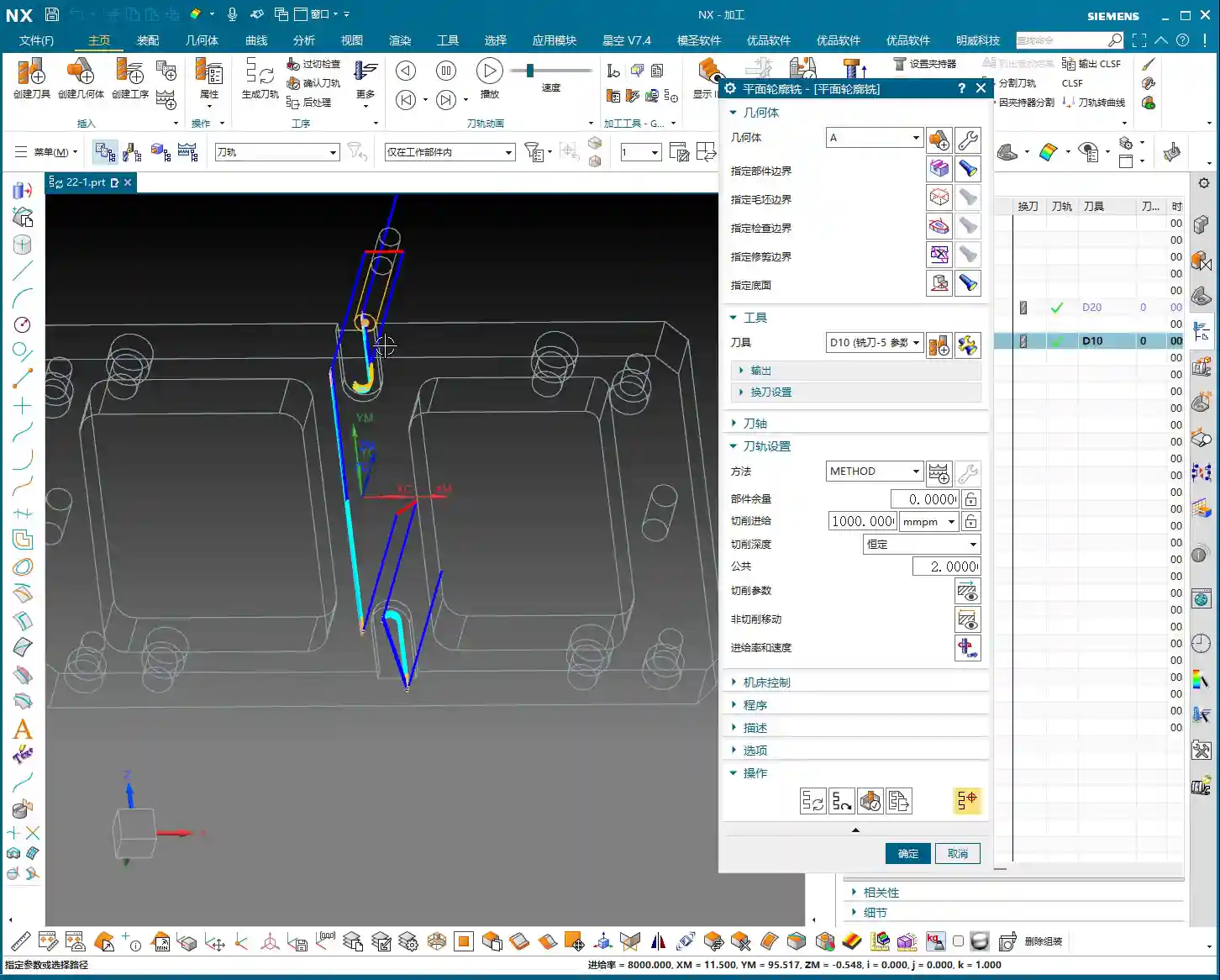
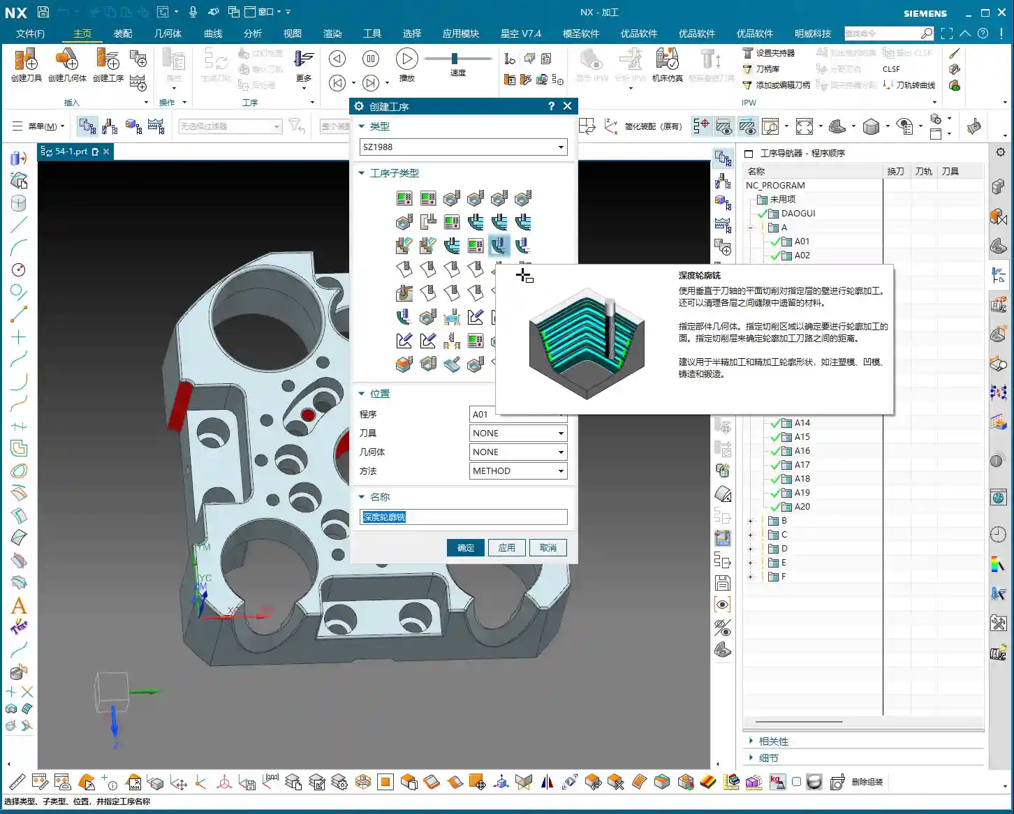
Listen up, Deep Contour Milling, as the name suggests, is for machining “contours.” So, how is this different from the “Planar Profile Milling” we discussed before? The difference is significant! While both machine contours, Planar Profile Milling is rigid; it only deals with **straight, vertical 2D sidewalls**. Give it an inclined surface or an arc, and it’s completely lost.
Our Deep Contour Milling, however, is a “versatile player.” Its greatest strength is its ability to handle **complex 3D surfaces**! Whether it’s inclined planes, fillets, radii, or various freeform surfaces – as long as it’s a sidewall, it can mill it precisely and smoothly. That’s why it’s our “go-to tool” for finishing, especially for precisely machining complex surface sidewalls.
Machining Strategy: The Frontrunner for Finishing
Before we dive into the NX operations, let’s get our strategy straight. Deep Contour Milling is specifically for **finishing, surfacing sidewalls, and Corner Cleanup**. Don’t even think about using it for Roughing; that’s like using a sledgehammer to crack a nut – it’s inefficient and puts unnecessary stress on the tool.
- Roughing: Remember, there are dedicated operations for Roughing, such as Cavity Mill, Face Milling, etc. These are designed for aggressive material removal. First, use Roughing to remove most of the material and mill out the blank’s basic shape.
- Finishing: By the time Deep Contour Milling comes into play, there should only be a thin layer of material remaining on the part. At this point, we use **small-diameter ball end mills or bull nose end mills**, combined with Deep Contour Milling, to finish the sidewalls, achieving the required accuracy and surface finish. Of course, for some tight corners or blind spots, you’ll need even smaller tools, or even custom-ground tools.
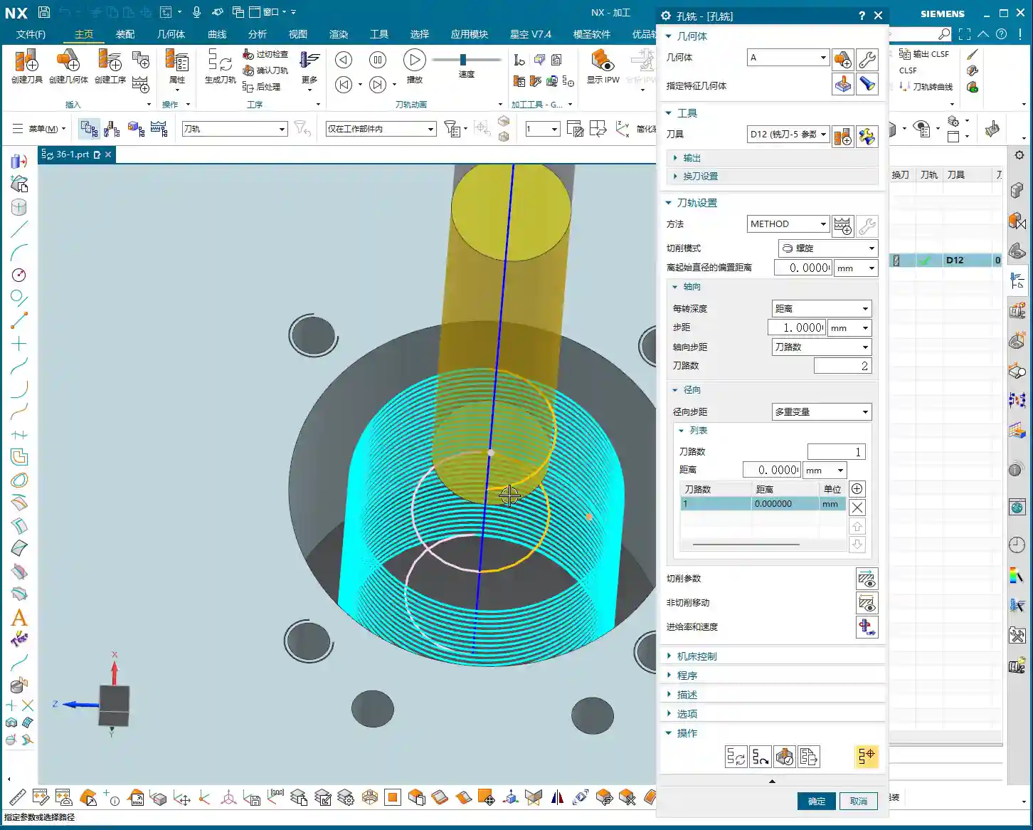
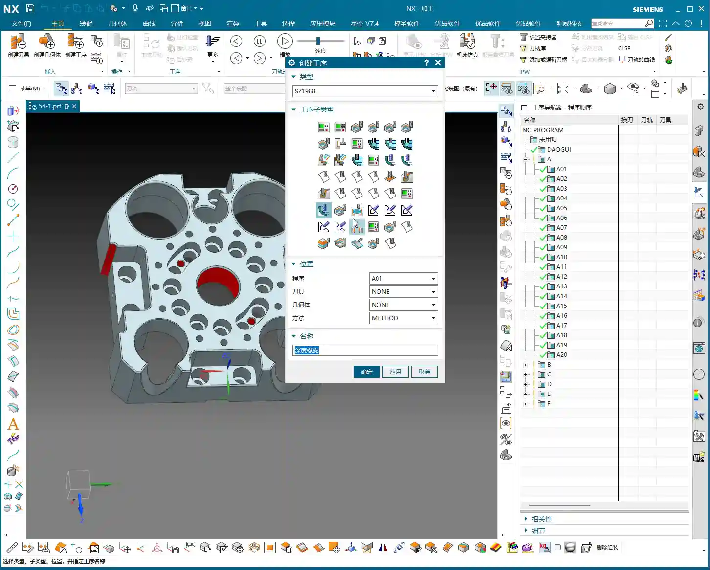
Sometimes you’ll see the “Deep Spiral” option; that’s actually a specialized helical feed strategy within Deep Contour Milling. It’s also for finishing sidewalls, and the principle is similar. Let’s put that aside for now and focus on the main concept.
Key NX Operations: Follow Master Wang and Avoid Years of Trial and Error

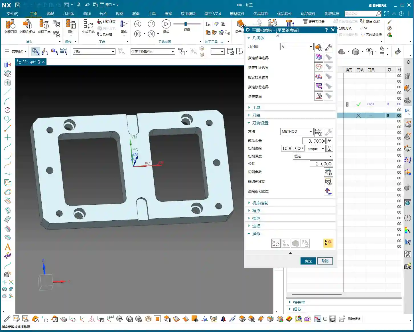
Step One: Work Coordinate System (WCS) Setup
This step is a common topic, but it still needs emphasizing. WCS setup is the foundation of all programming. This time, you don’t have to place it at the part’s center. You can place it at any corner, for example, a “pinch point” on the model, then rotate it 180 degrees so the X-axis aligns with your preferred machining direction. Remember, this is just a matter of preference and doesn’t affect your final programming logic or toolpath.
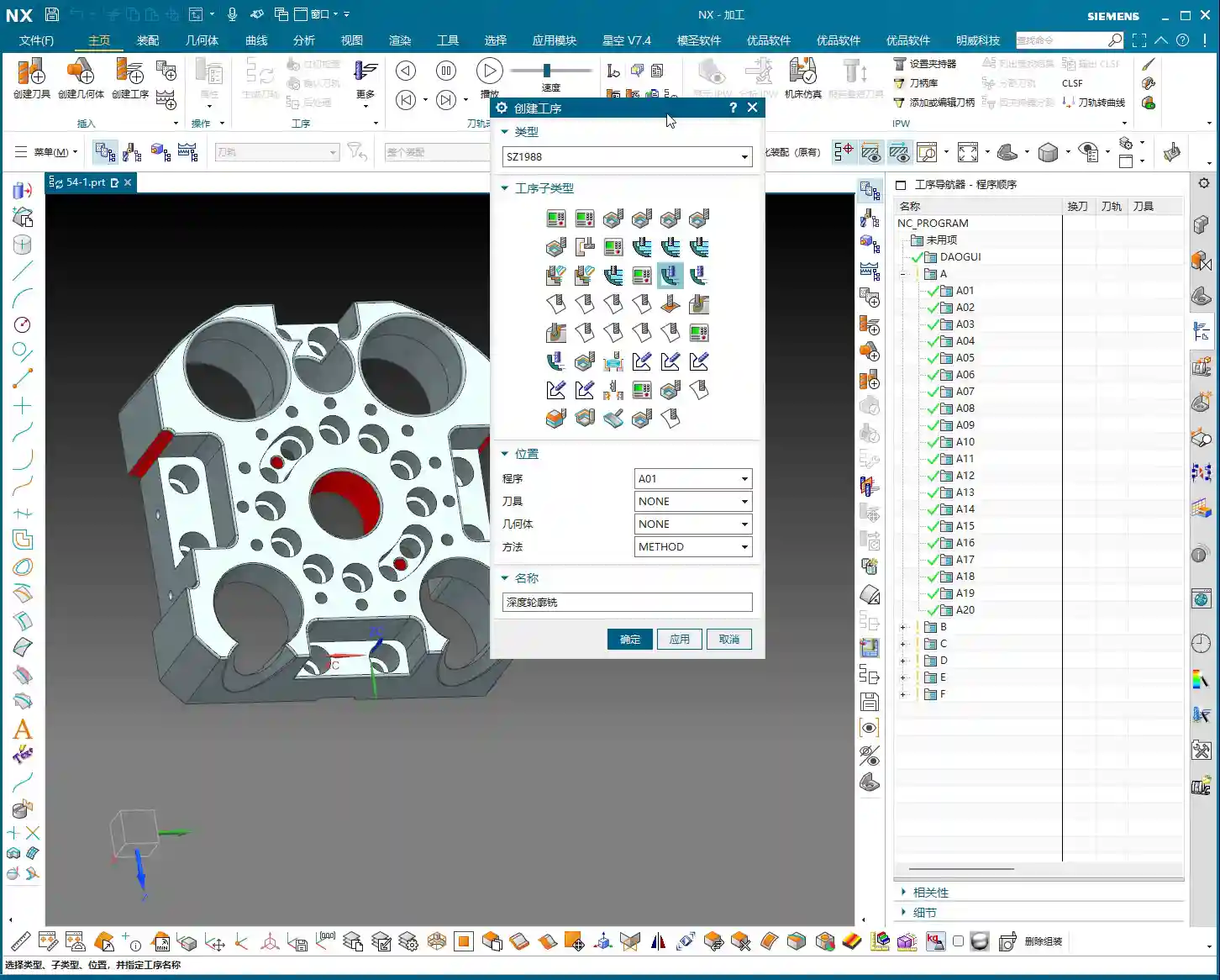
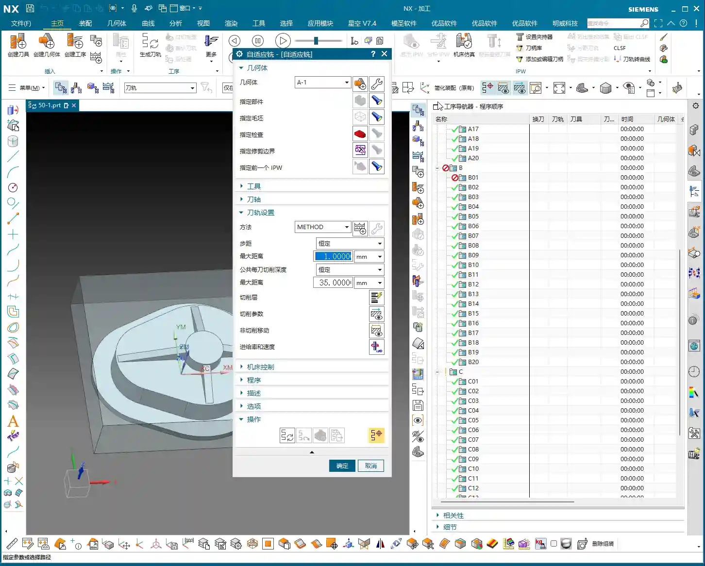
Each time, we must first create a **Workpiece** geometry and then specify our **Part** and **Blank**. However, since Deep Contour Milling is mainly for finishing, the blank has usually been largely machined already. So sometimes, you can directly delete the blank and keep only the part, which speeds up software calculations.
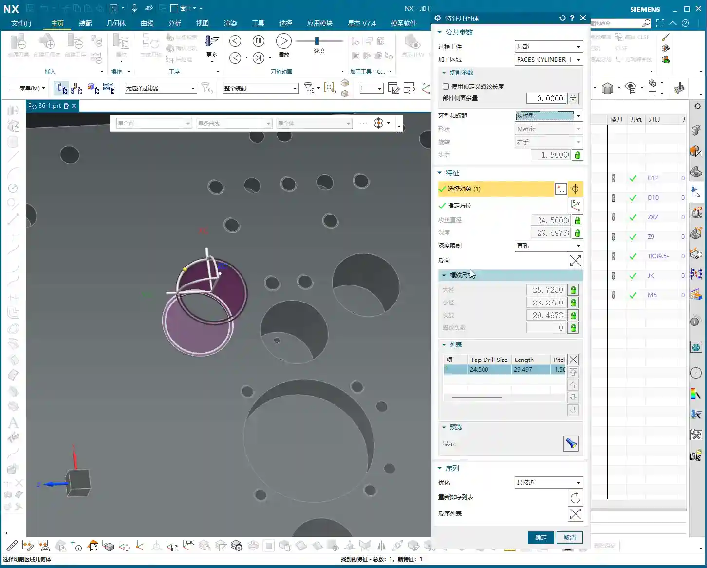
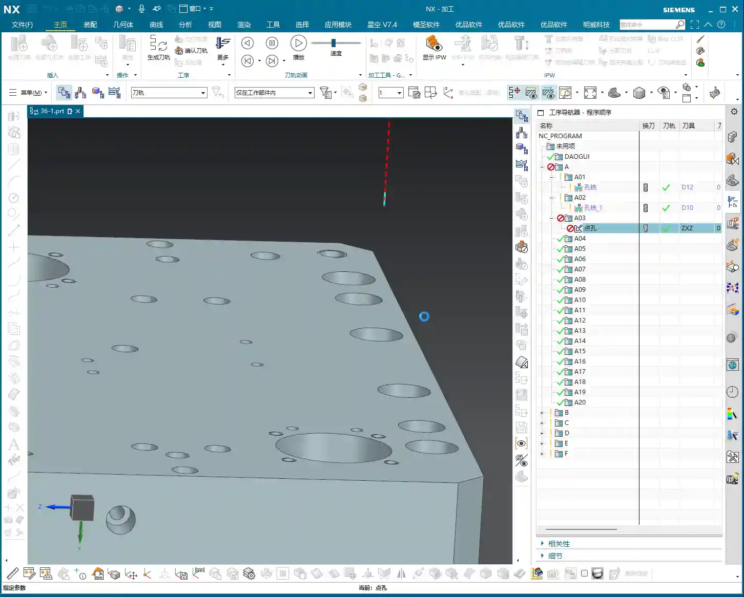
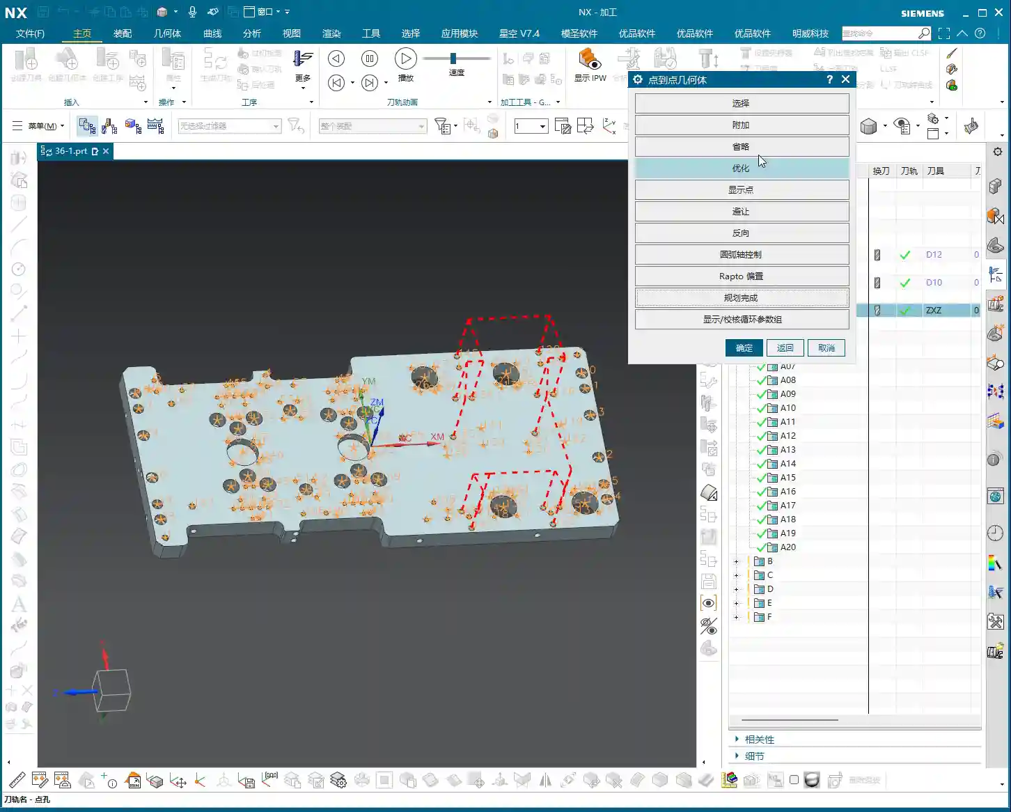
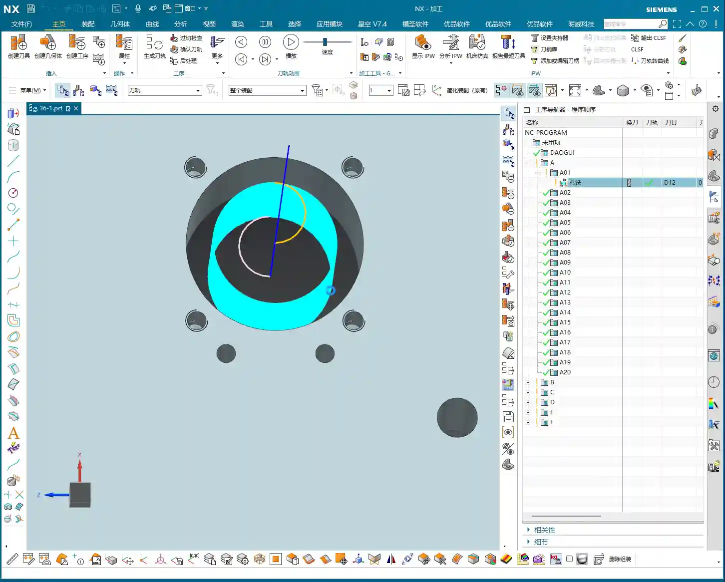
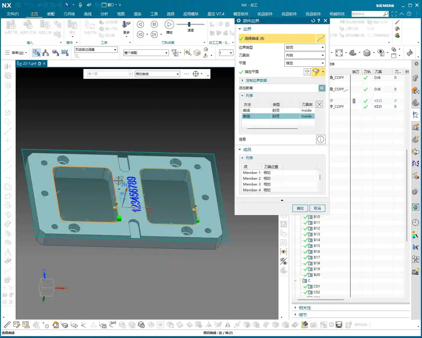
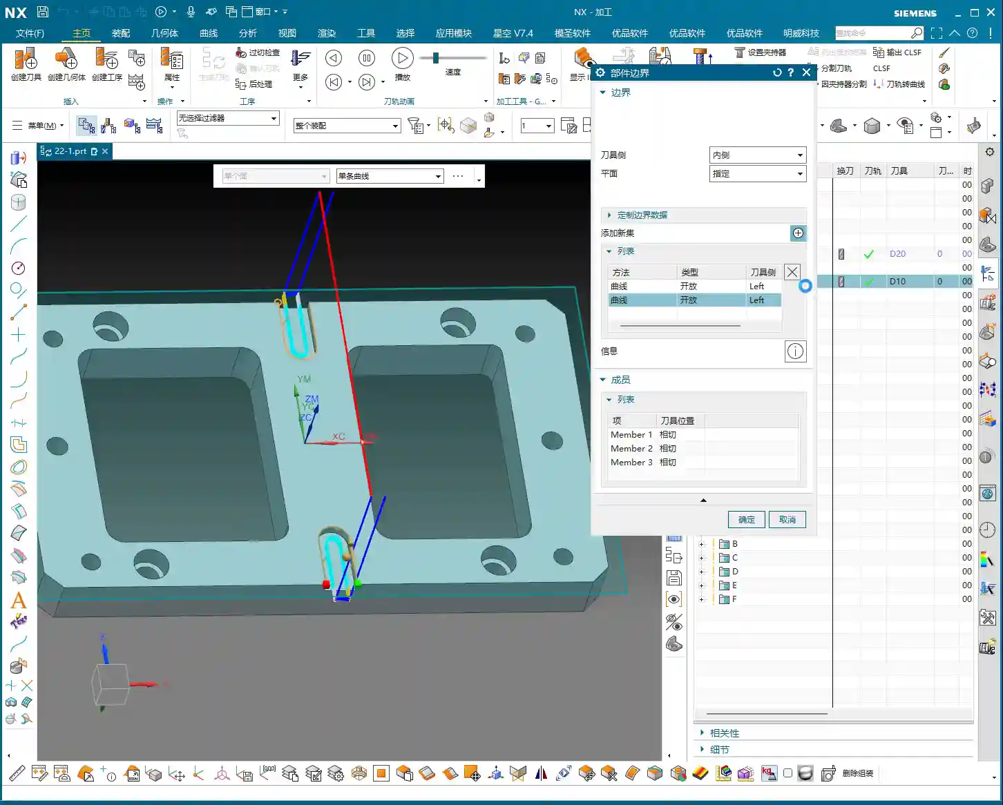
Step Two: Specifying the Machining Area – Avoiding the “Select All” Trap
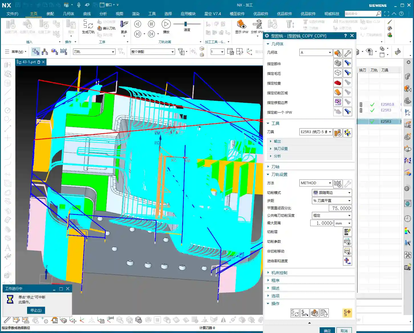
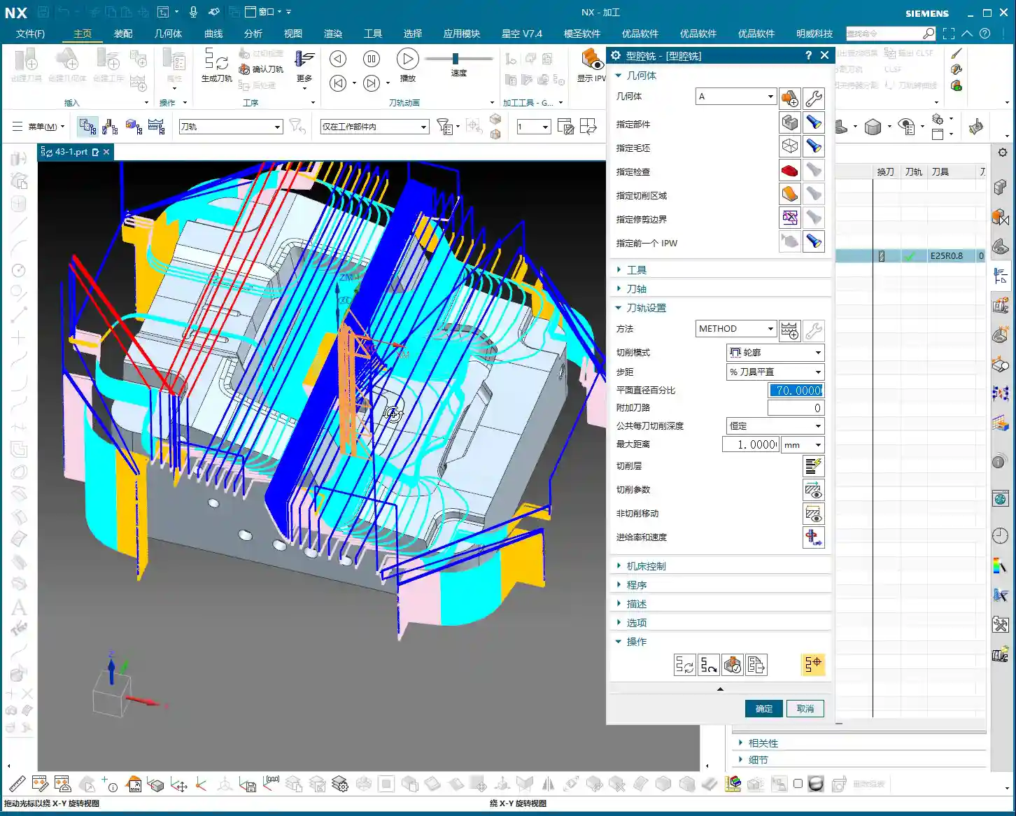
This is a crucial point! After entering the Deep Contour Milling operation, besides specifying the part, the most critical step is **”Specify Cut Area.”** Why emphasize this? Because new programmers often have a habit of blindly selecting the entire part. The tool then runs unnecessarily over areas that don’t need machining, which is a waste of time and increases wear.
The essence of Deep Contour Milling lies in its ability to precisely machine your desired **local sidewalls**. For instance, if you only want to finish the sidewall of a specific hole or the inclined surface of a certain step, you must **explicitly specify these areas**. If you don’t, it won’t know where to machine.
During the operation, open the “Specify Cut Area” option, then directly select the faces you want to machine on the model. This way, the toolpath will only be generated within this specific area, ensuring both efficiency and precision.

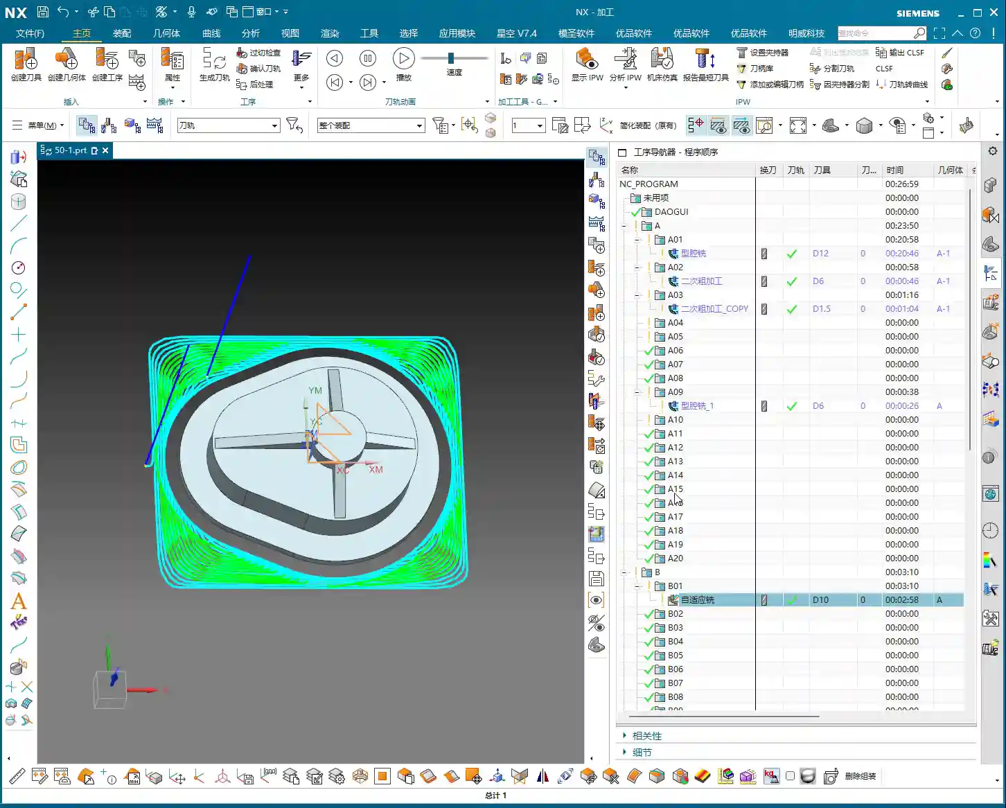
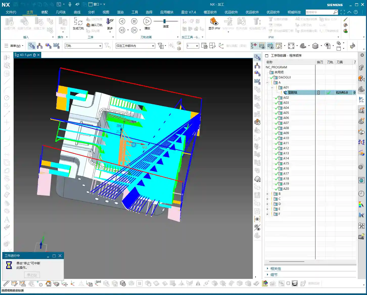
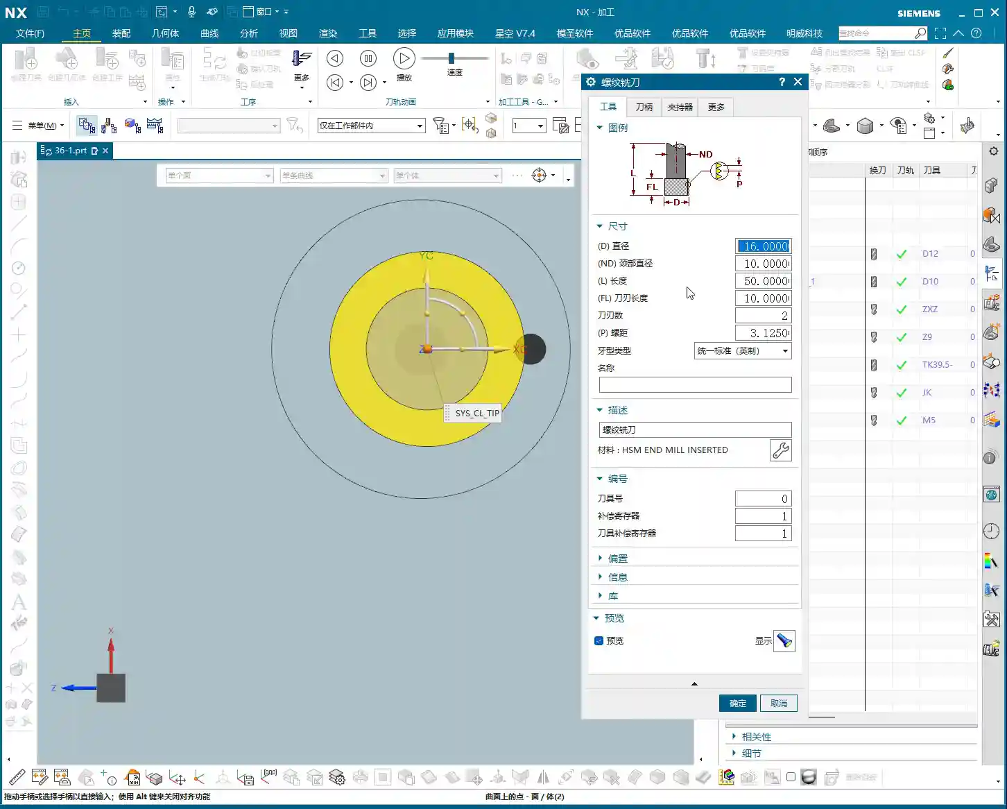
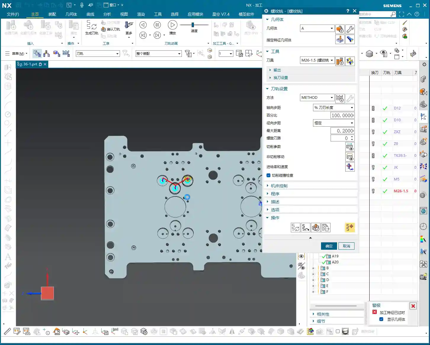
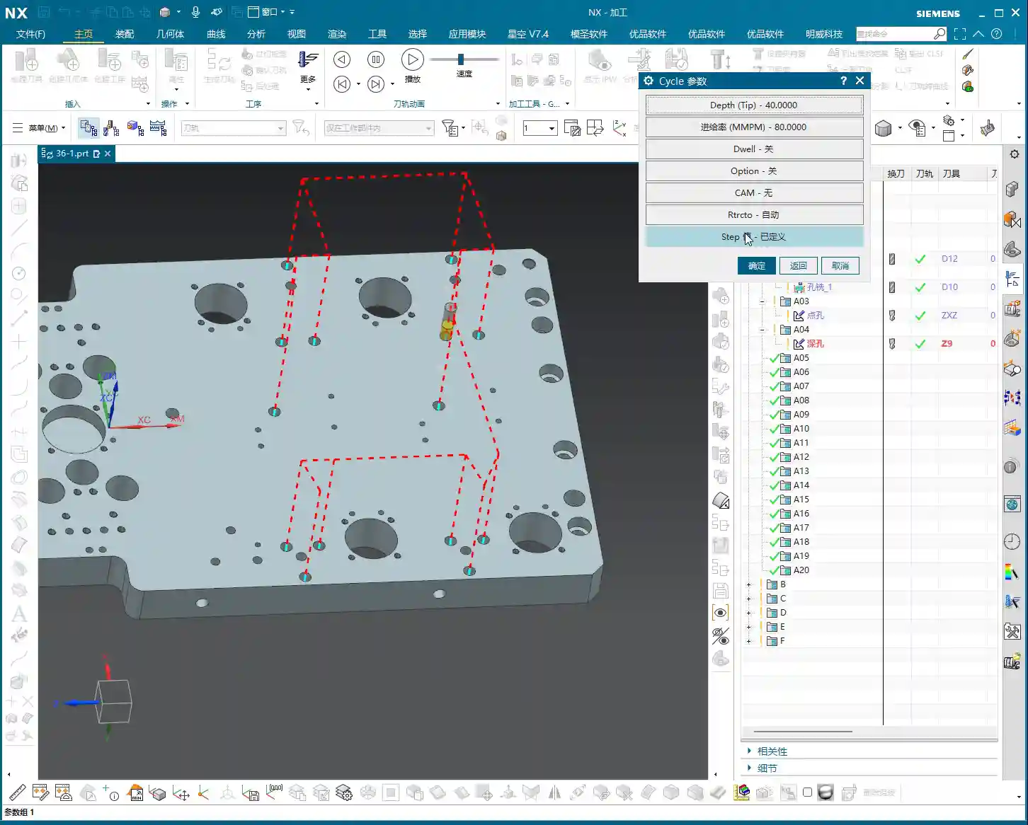
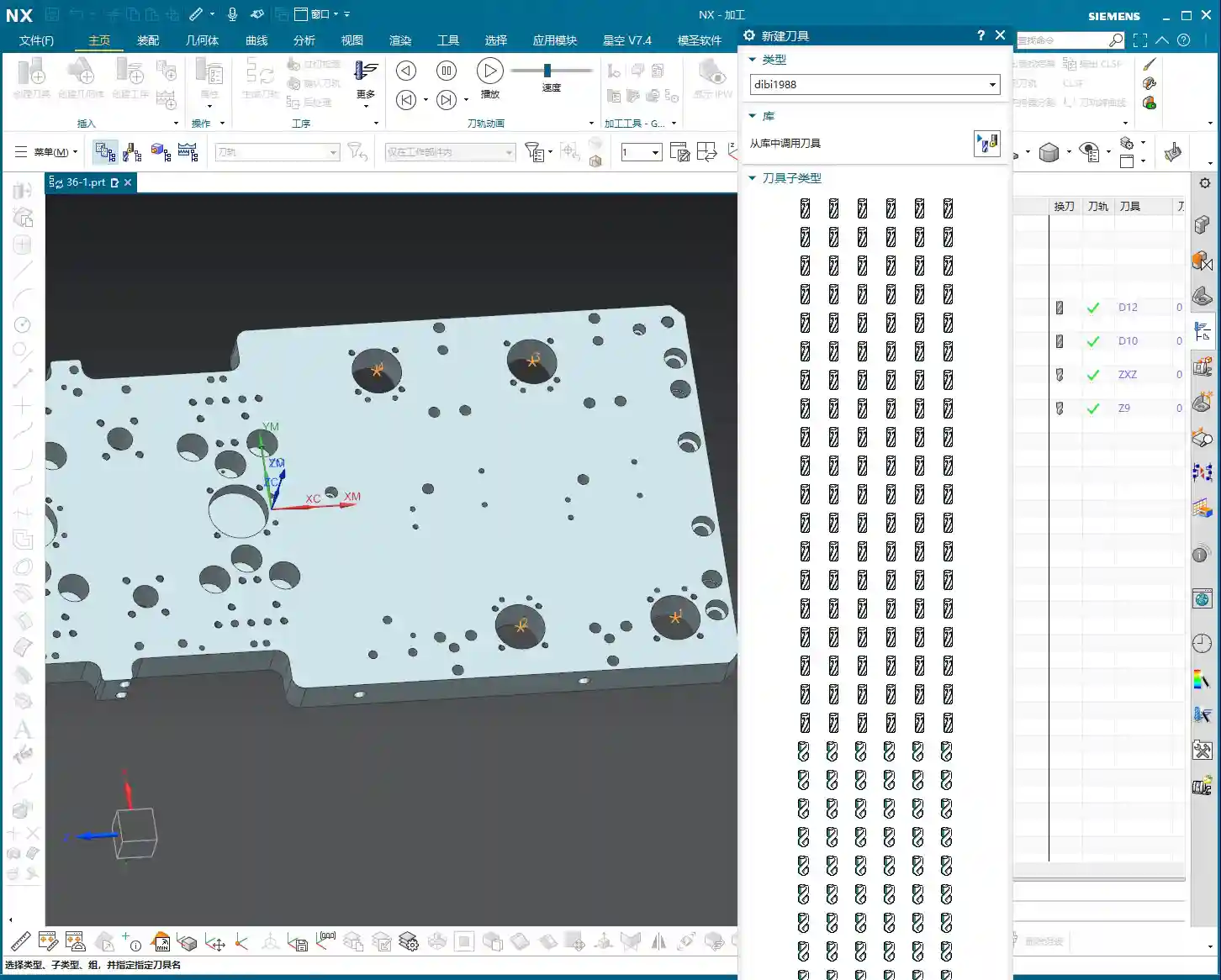
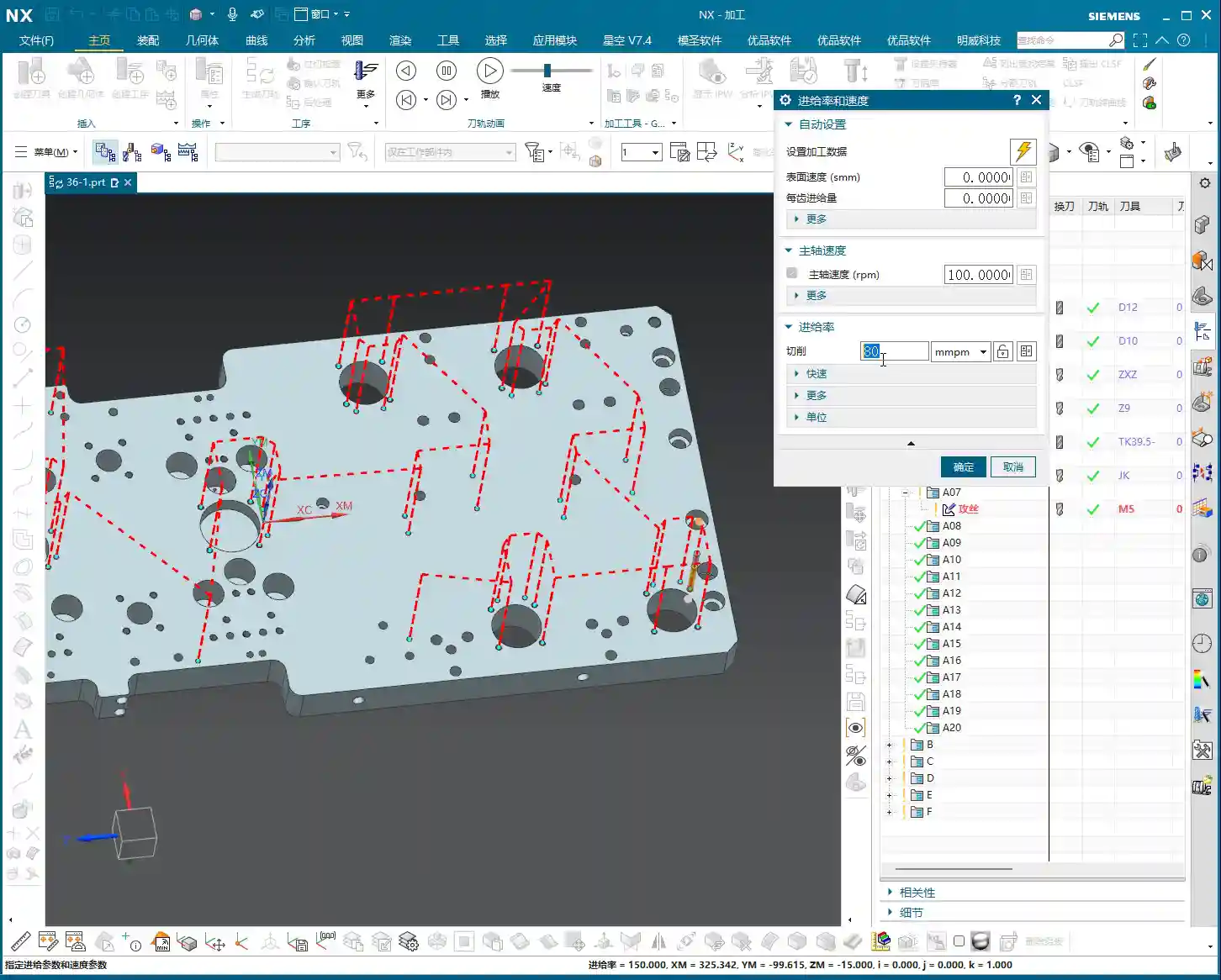
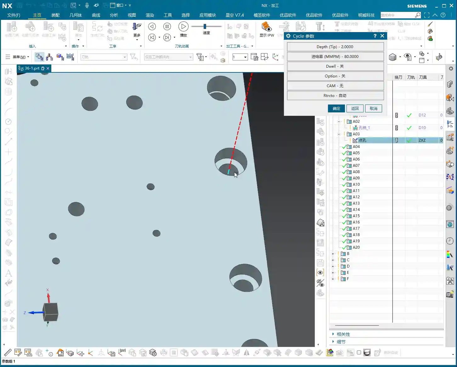
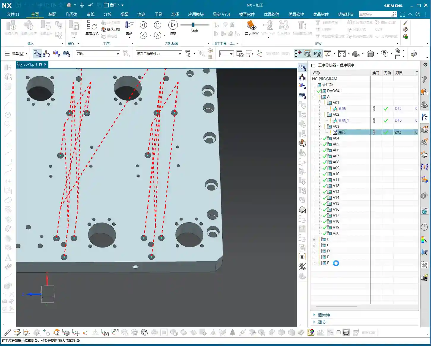
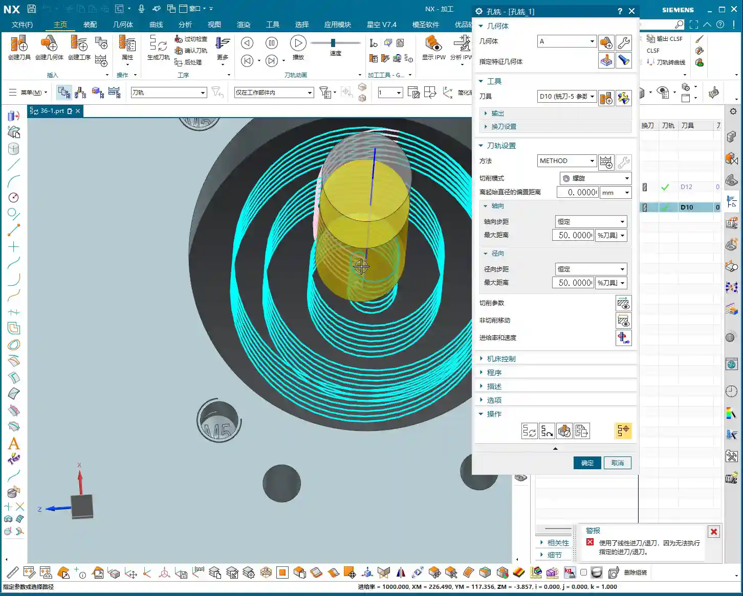
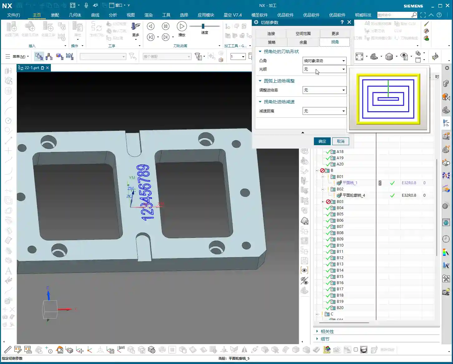
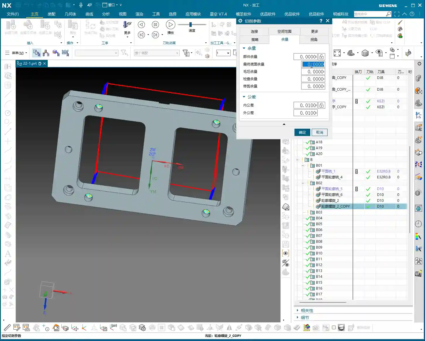
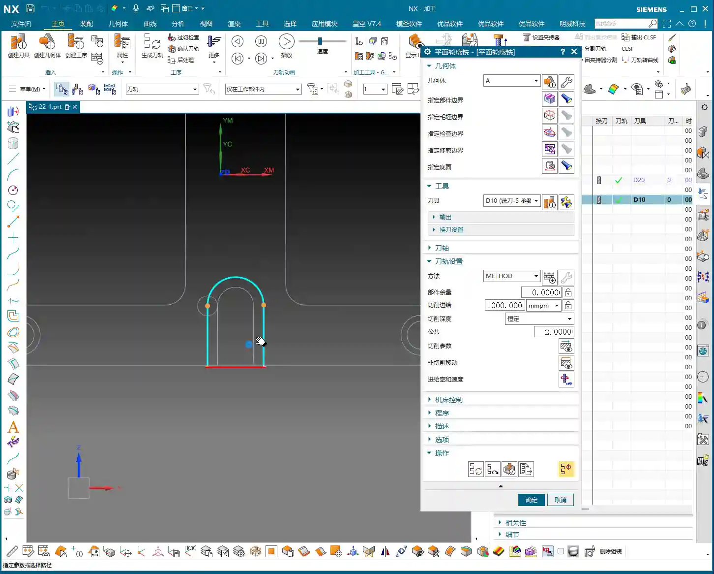
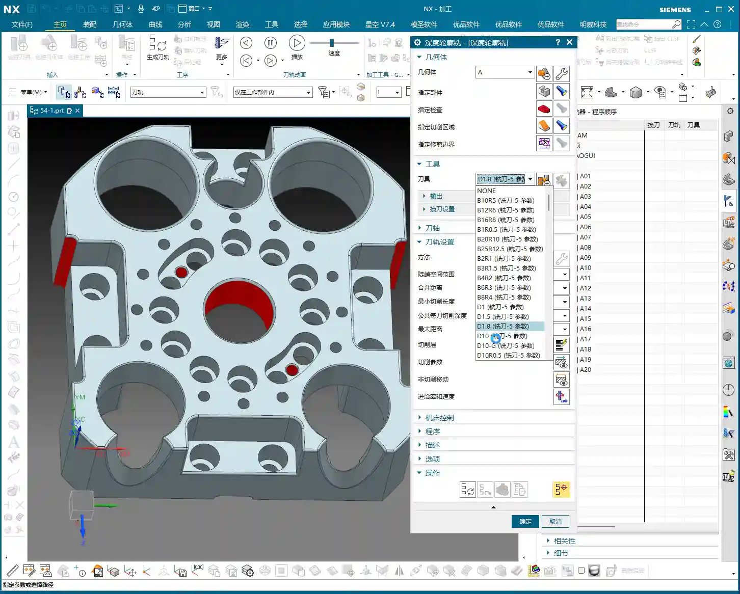
Step Three: Tool Selection and Toolpath Generation
Tool selection depends on the features you intend to machine. For example, to clean up an R5 fillet, you can’t possibly use a D10 tool, can you? Typically, flat end mills or bull nose end mills are used for finishing sidewalls, while ball end mills are commonly used for Corner Cleanup. Remember to choose the right tool, such as a D10 end mill for finishing a relatively large bore wall.
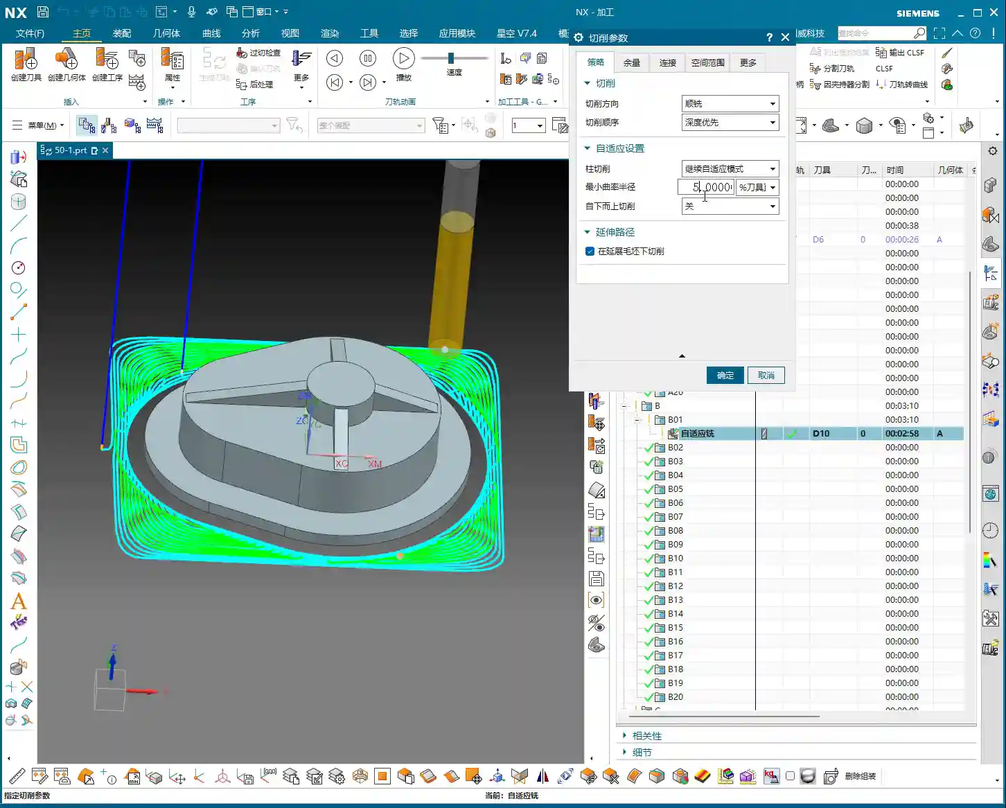
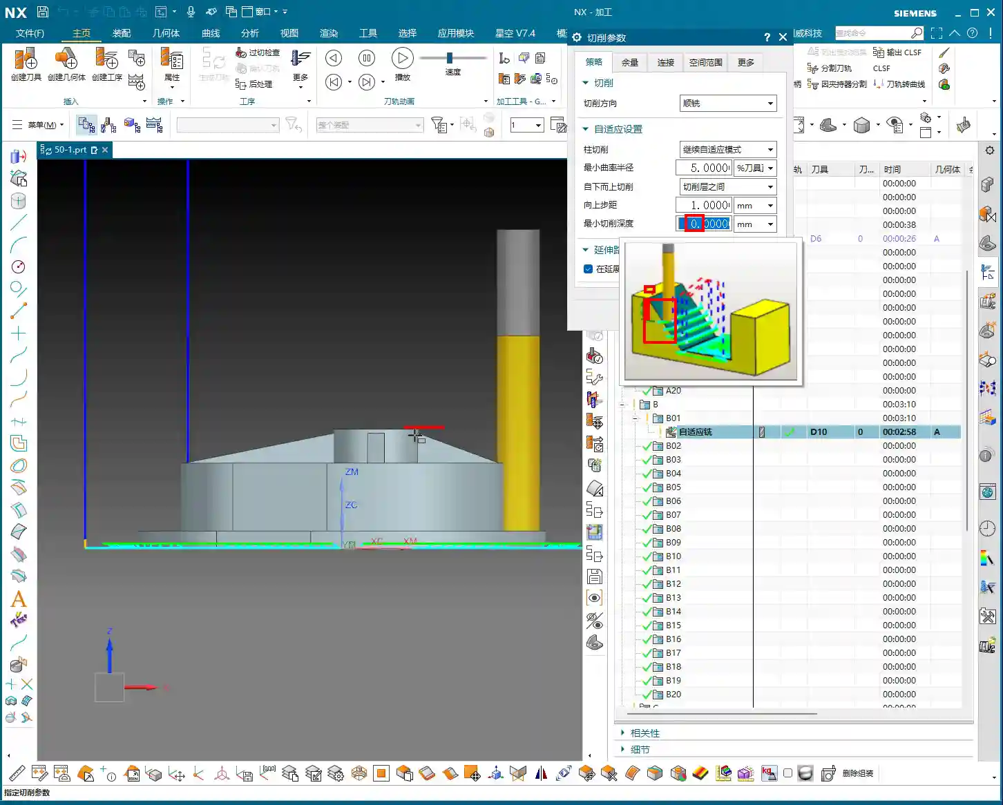
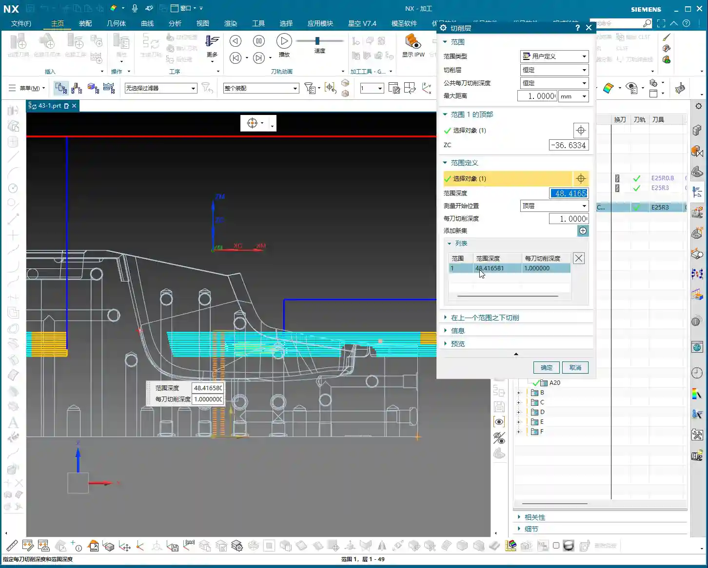
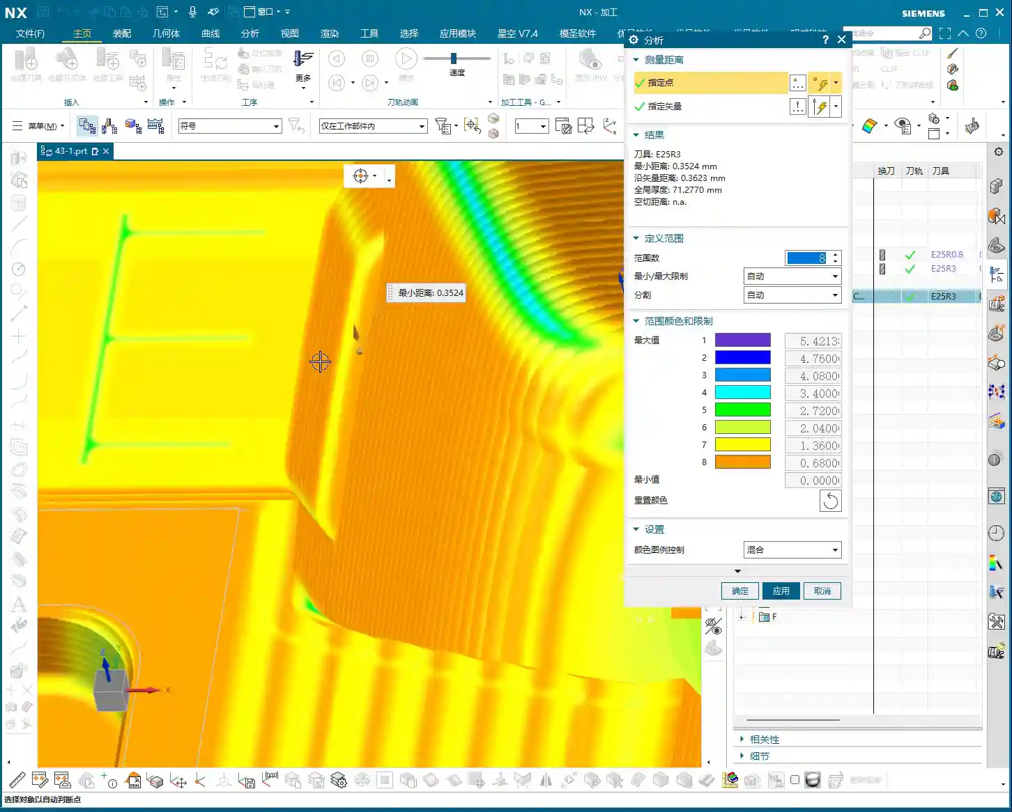
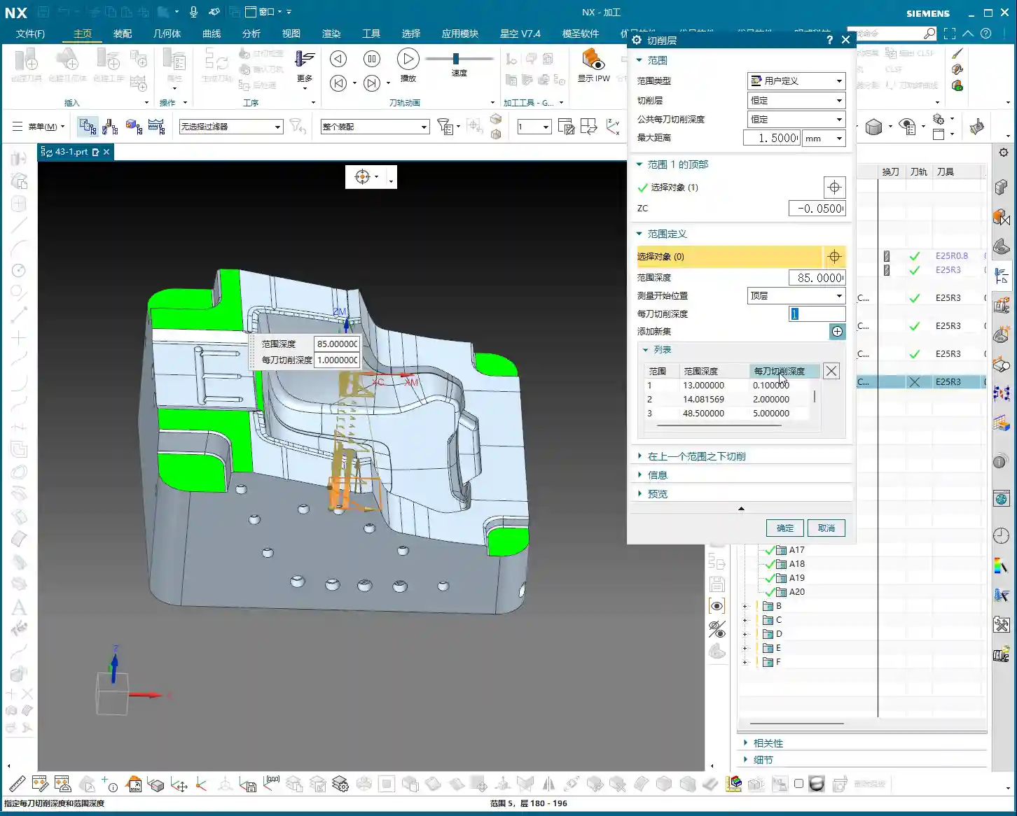
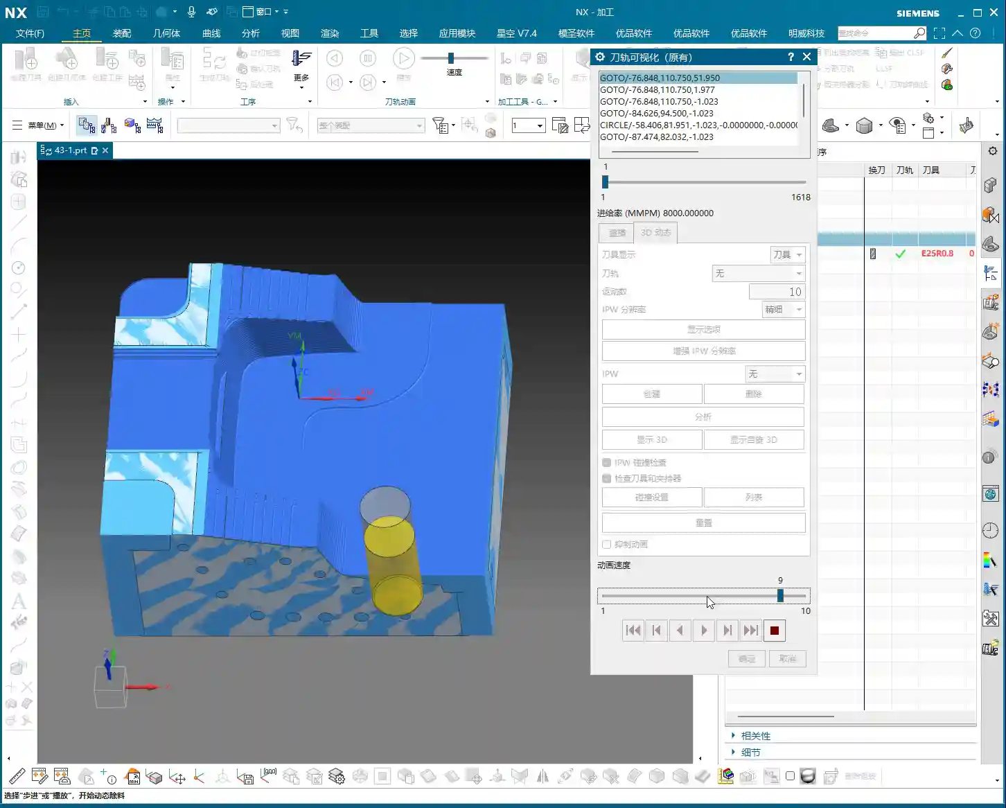
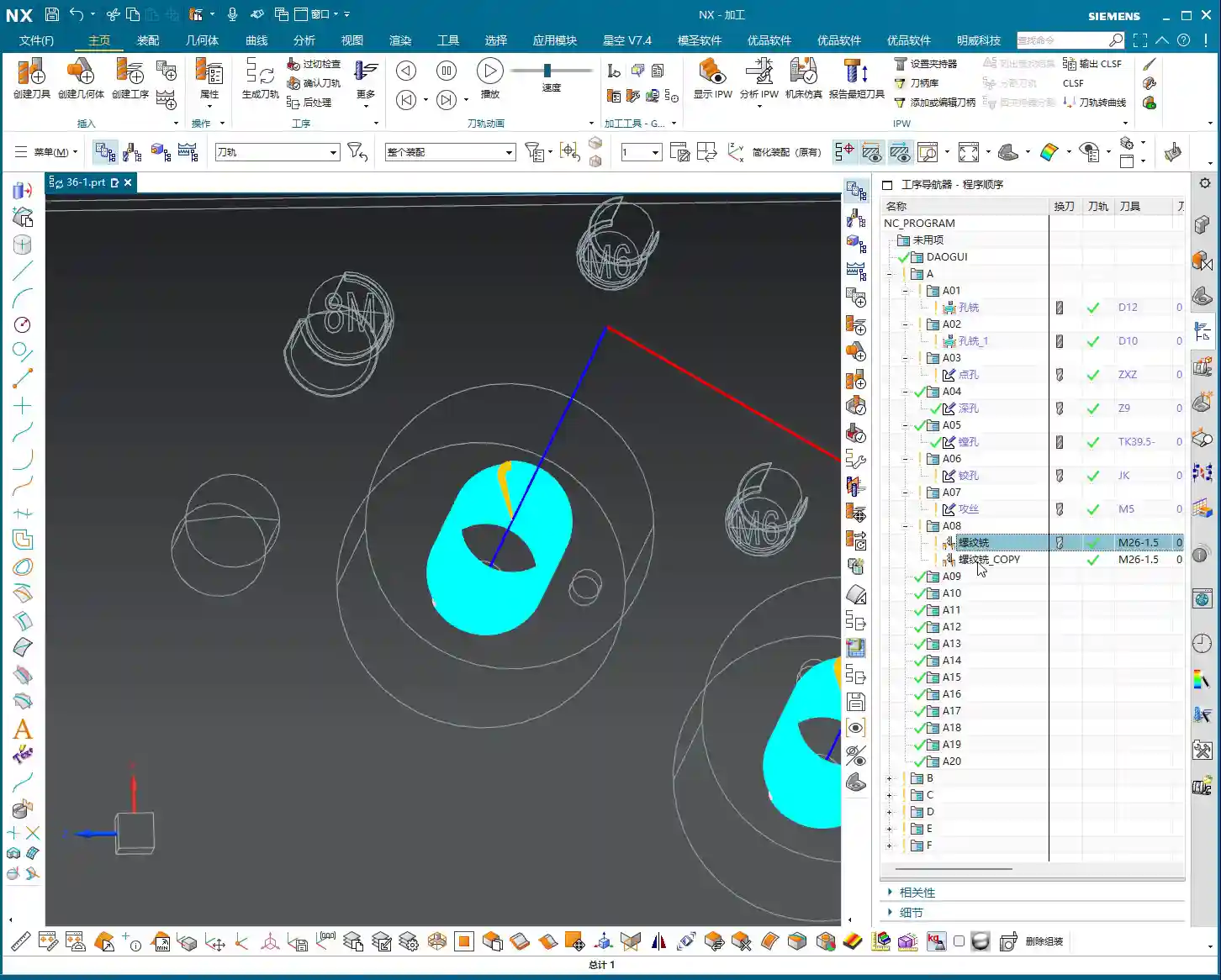
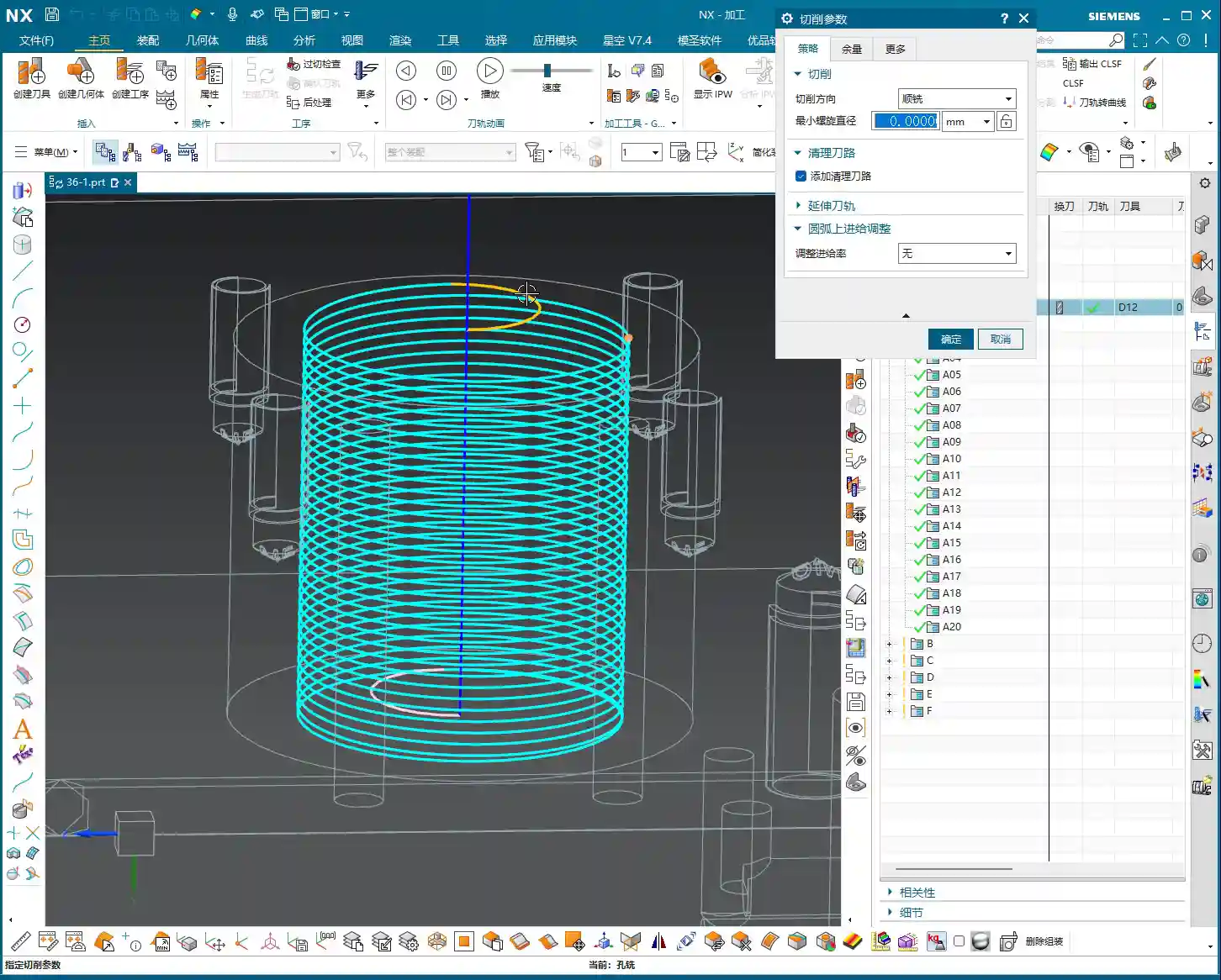
Once all parameters are set, it’s time for the “stroll” phase – toolpath generation. You young folks, don’t just stare at the computer screen. After the toolpath is generated, you must **carefully simulate and inspect it**. Check if the tool’s trajectory is reasonable, if there are any air cuts, overcuts, or areas prone to heavy Depth of Cut (DOC). Software simulation alone won’t show you machining sparks, so experience and visual inspection are indispensable.
Master Wang’s Pro Tips: Tricks to Boost Efficiency

NX View Rotation Trick
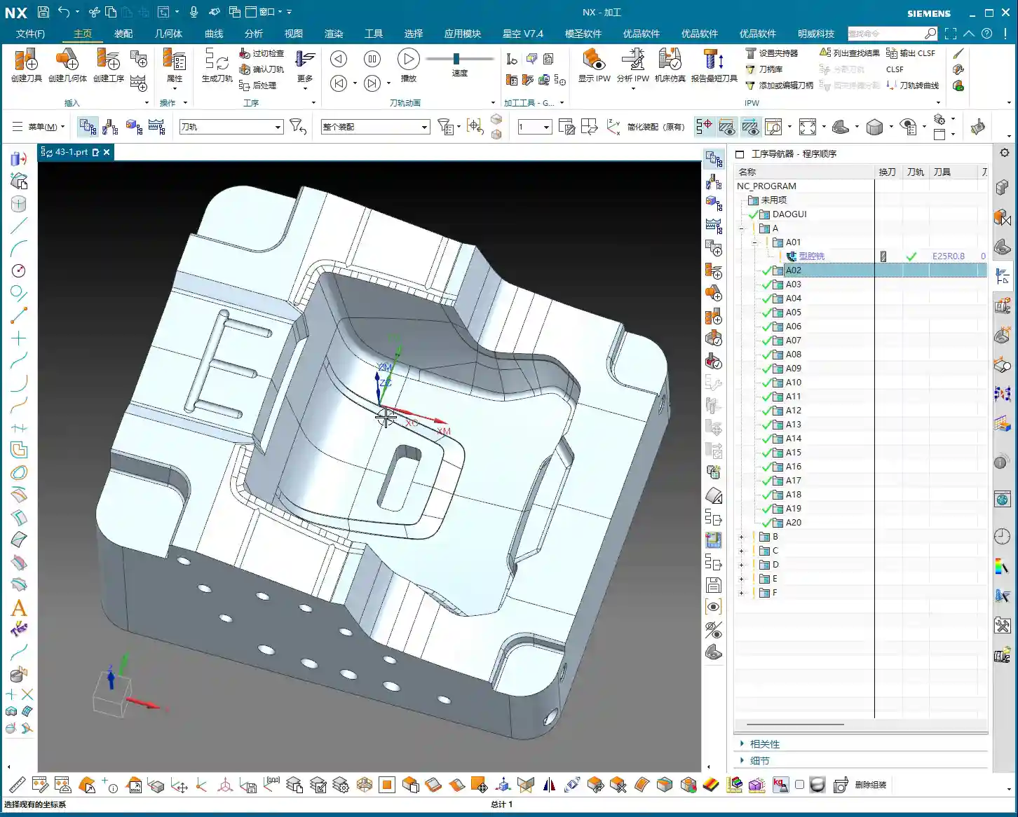
When rotating models in NX, do you often find the model flying off, not rotating to the position you want to see? That’s because you haven’t identified the correct center point for rotation.
Listen up, here’s a little trick: When you need to observe the model around a specific point (like a hole or a fillet), **hold down the middle mouse button on that point, don’t release it**, then drag the mouse to rotate. You’ll then notice that the model rotates around the point you’re holding, making observation much easier! This trick isn’t something textbooks necessarily teach you; it’s something we’ve picked up through hard work and experience on the shop floor.
Leverage NX Effectively to Avoid Repetitive Work
Many operations in NX are interconnected, such as “Specify Part,” “Specify Blank,” and “Specify Cut Boundaries.” Once you’ve learned them, there’s not much more to say. Practice more, think more. Only by mastering these fundamentals can you free up your mind to explore more advanced techniques.
In our next lesson, we’ll delve deeper and thoroughly review the other options within Deep Contour Milling. That’s all for today. See you next time!

Summary: Guide to Avoiding Common Mistakes
- DO NOT use Deep Contour Milling for Roughing! It’s a powerful tool for Finishing, not a brute-force tool for Roughing. Using it for Roughing is not only inefficient but also prone to tool wear and part damage.
- Precisely Specify the Cut Area! Don’t be lazy, and don’t “select all.” Select the specific sidewall surfaces that require machining to ensure efficient and precise toolpaths.
- Inspect the Toolpath! After the toolpath is generated, always simulate it carefully. Observe the tool’s entry and exit moves, and its cutting path, to confirm there are no overcuts, collisions, or air cuts. This will save you a lot of trouble compared to rework later.
- Understand the Difference Between 2D and 3D! Planar Profile Milling only handles straight walls, while Deep Contour Milling can tackle all kinds of sidewall surfaces. However, neither is suitable for machining large flat surfaces. Choosing the right operation will make your work twice as effective with half the effort.
👤 About the Author:
The author is a veteran CNC machining professional with 15 years of industry experience, specializing in UG NX programming. This article is an original work representing personal practical insights.
⚠️ Copyright Notice: Unauthorized reproduction or distribution without prior communication is strictly prohibited.