📝 Key Takeaways: Master Wang provides a detailed explanation of UG NX toolpath optimization, focusing on “Tool Rolling” and “Cut Below Tool Contact Point.” This ensures clean edges and thorough corner cleanup at the bottom, eliminating residual material and avoiding air cuts. The tutorial offers an in-depth analysis of the practical advantages and disadvantages of “Cut Between Levels,” emphasizing that for complex parts, side walls and bottom surfaces should be machined separately to enhance both efficiency and quality. This guide distills fifteen years of hands-on experience, imparting techniques not found in textbooks, to help you truly master NX programming.
Master Wang’s Talk: Advanced Siemens NX Machining Techniques
Hello everyone, I’m Old Wang. I’ve been in this industry for fifteen years, and the experience I’ve gained from hands-on work in the shop floor—that’s something you won’t learn from textbooks. Today, we’re not going to talk about abstract theories; we’re diving straight into practical insights. Let’s discuss some easily overlooked parameters in Siemens NX programming that have a huge impact on machining quality and efficiency.
Especially for complex surfaces and precision parts, these details determine whether you get it “right the first time” or have to “rework and modify the mold.” Listen up, this is all hard-earned, valuable experience.
I. Tool Rolling: Making Your Toolpaths More “Smooth”
In Siemens NX “Z-level Profile Milling” or “Depth Contour Milling” operations, we often encounter an option called “Roll Tool on part edges”. Many novices might think this is an unimportant option, or simply don’t know what it does. But Master Wang tells you, if you use this correctly, it can significantly improve the edge quality of your part.
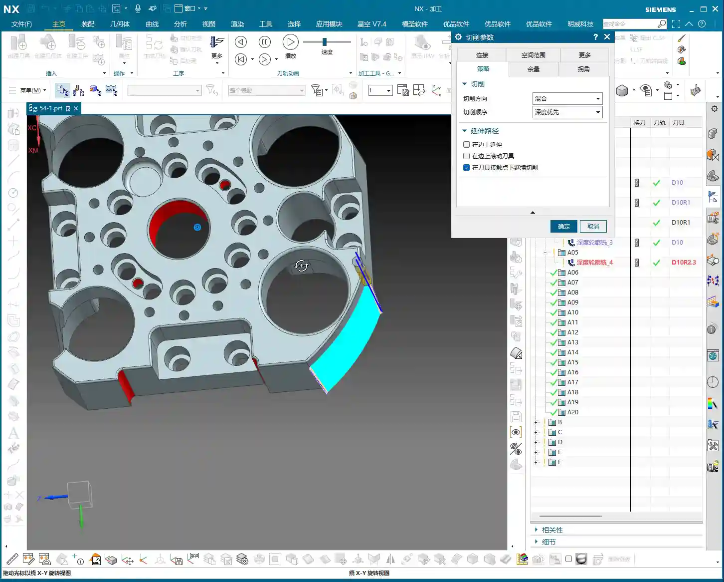
What is Tool Rolling?
Let’s use an analogy. With a normal toolpath, when approaching a right angle or sharp corner, the tool’s center path directly follows the model’s edge, and the tool side “cuts straight through.” However, if you select “Roll Tool on part edges”, the software automatically adjusts the tool’s tilt angle, allowing the tool to “roll” smoothly over these edges. This is like running your hand over a sharp edge: is it more painful to slide straight across, or more comfortable to roll over it slightly tilted? Rolling over it is definitely smoother.

Practical Application and Key Pitfalls to Avoid
- Purpose: Primarily to improve the surface quality of part edges, reduce burrs, and prevent tool impact. This effect is especially noticeable when machining parts with chamfers or fillets. It helps distribute cutting forces more evenly and extends tool life.
- Effect: You’ll notice the toolpath will “turn slightly” when approaching an edge, as if to “smooth out that little corner”. Don’t just stare at the simulation in the software; those are theoretical paths. On the actual machine, you need to observe the cutting sparks and listen to the cutting sound to determine if the tool is running smoothly and engaging properly.
- When to Use: Generally, if you’re only performing roughing or if edge finish requirements are not high, you typically don’t need to select this option. The extra “rolling” motion might slightly increase machining time. However, for finishing passes, especially for edge refinement on high-precision parts such as mold cavities or turbine blades, this option becomes very important.
II. Cut Below Tool Contact Point: The Secret to Clearing Residual Material
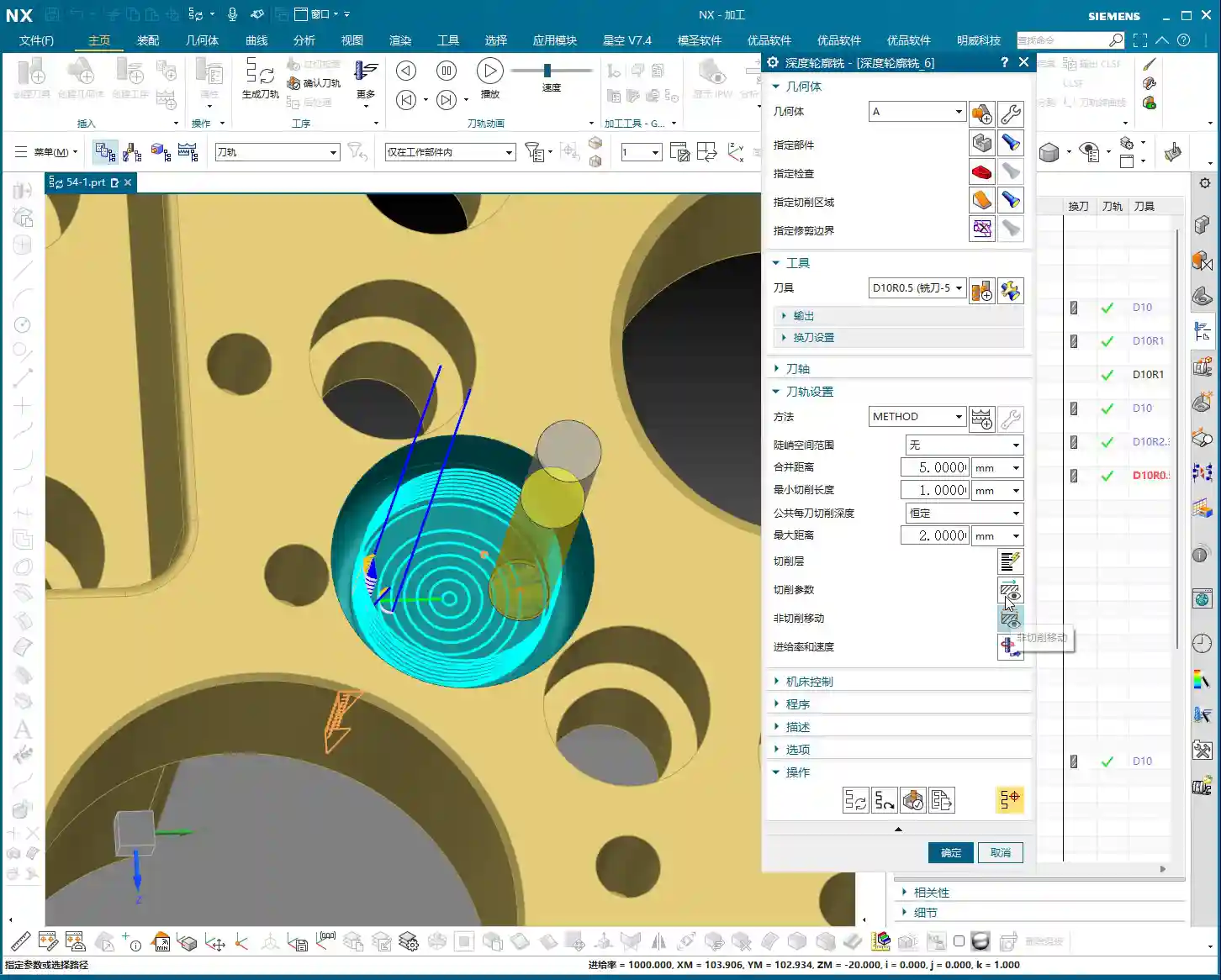
This option in Siemens NX is called “Cut below tool contact point”. Often, when machining a curved surface with a ball end mill or a radius tool, theoretically the tool reaches the bottom, but in reality, a small amount of residual material might still be left along the bottom edge. This is due to the tool’s geometry.

Core Principle: True Contact Between Tool and Workpiece
Imagine you’re using a ball end mill to machine a deep groove. When the theoretical tool contact point (typically the tool tip or the lowest point of the radius) reaches the bottom edge of the groove, if “Cut below tool contact point” is not selected, the software will consider that spot “machined to depth,” and the toolpath will stop extending downwards. However, due to the spherical part of the ball end mill, a small amount of unmachined material might still be hidden beneath the edge. The software won’t continue cutting further down because it believes there’s nothing left for the tool to contact on that main surface.
However, when you select this option, Siemens NX intelligently determines that even if the theoretical tool contact point has reached the boundary, as long as the tool’s “actual cutting portion (e.g., the spherical part of a ball end mill)” can still engage the model, it will continue extending the cut downwards until the residual material in that corner is completely removed. As illustrated in the diagram, one toolpath will extend further down than the other.
An Essential Option for Precision Machining
- Function: Ensures that residual material at the intersection of vertical walls and bottom surfaces is completely removed, resulting in sharper, more precise edges. This is crucial for parts requiring strict dimensions and surface quality.
- Misconception: Some might think this could lead to overcutting, but that’s not the case. Siemens NX considers the tool’s true geometry during calculations and won’t cut downwards indefinitely. It only machines material that “theoretically should be cut, but might be missed due to tool geometry limitations.”
- Efficiency and Quality: If you don’t select this option, you’ll likely need a second tool or subsequent manual finishing to remove these residual materials, which undoubtedly increases cost and time. Especially when machining deep pockets, ribs, or performing corner cleanup on molds, this option can save you a lot of trouble.

III. Cut Between Levels: Optimizing Paths to Improve Surface Finish
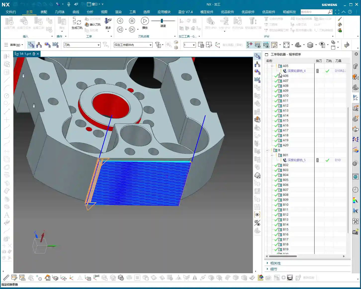
In Siemens NX machining operations, especially in some 3D milling strategies like “Depth Contour Profile” or “Z-level Profile Milling”, you might see the parameter “Cut between levels”. This function is primarily designed to add extra toolpaths between existing cutting levels to achieve a better surface finish or more uniform machining allowance.
Principle and Application Scenarios
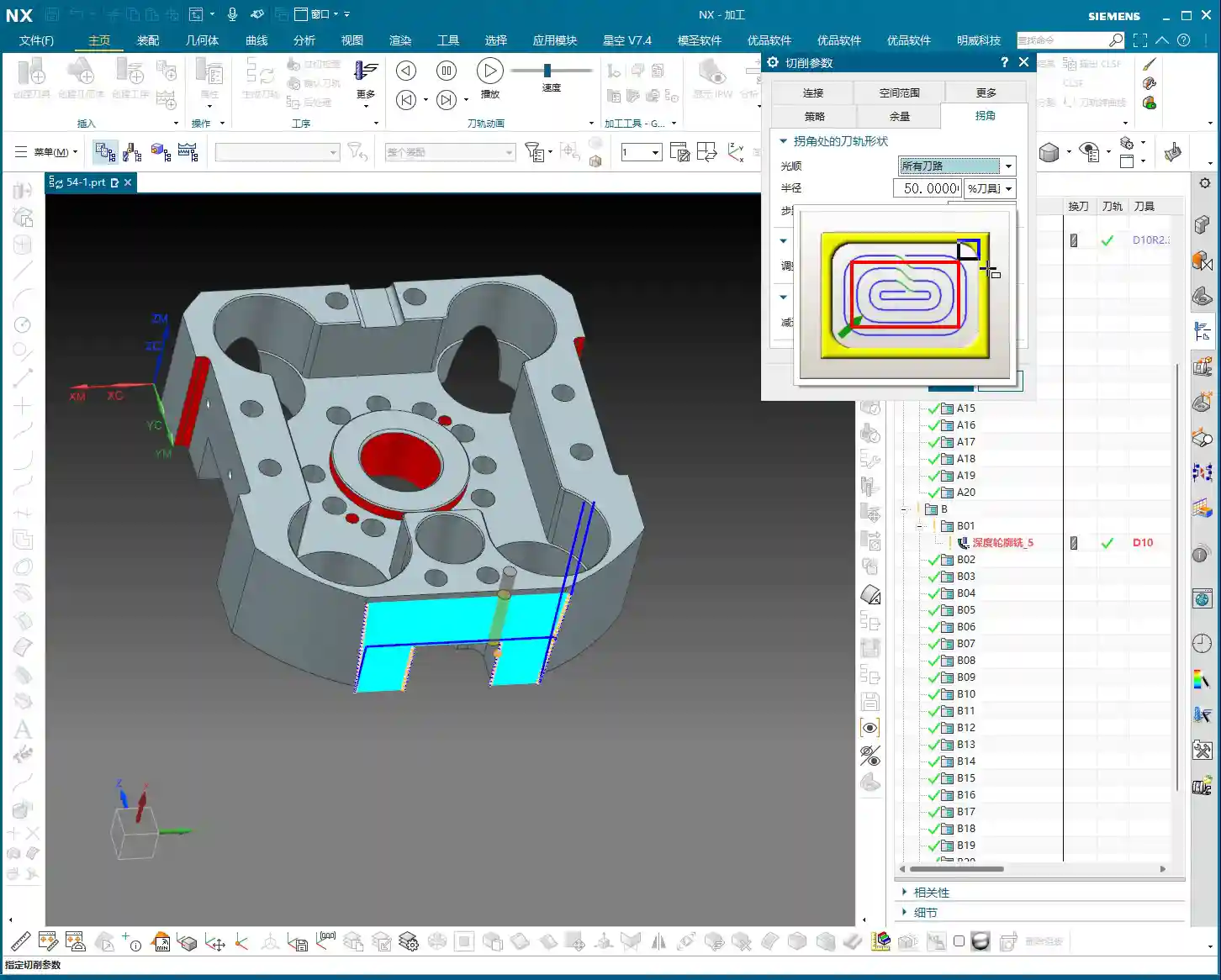
As its name suggests, Cut Between Levels inserts additional intermediate toolpaths between our established normal cutting levels. It doesn’t simply increase the Depth of Cut (DOC), but rather, builds upon existing toolpaths by adjusting the stepover to increase the cutting density on angled and curved surfaces. The result is a reduction in the “stair-stepping” marks left by the previous tool on these surfaces, leading to a smoother surface transition.
- Advantages: For finishing passes on parts requiring high surface finish, Cut Between Levels can significantly improve results. It can effectively reduce surface roughness without substantially increasing overall machining time.
- Disadvantages (to Note): If misused, especially on complex open geometries, it might generate redundant toolpaths or even “imperfect” toolpaths, which can actually decrease efficiency.

Master Wang’s Practical Experience: Separate Machining is More Reliable
Although Siemens NX provides some conveniences, allowing you to process both side walls and bottom surfaces simultaneously in a single operation using Cut Between Levels—for example, in “Depth Contour Milling”, when you select it, it will attempt to finish the side walls and then finish the bottom surface as well. However, having worked in this field for so many years, my advice to you is: unless it’s a very simple part, always try to machine the side walls and bottom surfaces in separate finishing passes!
Why?
- Control: Separate machining allows for more precise control over the machining parameters for each area. The cutting conditions, tool selection, and stock allowance strategies for bottom surfaces and side walls can differ significantly.
- Machining Stability: For “open geometries,” forcing a single toolpath to simultaneously finish side walls and bottom surfaces can very likely lead to “less-than-perfect” toolpaths, or even issues like chatter and overcutting.
- Not for Novices: For beginners just learning Siemens NX, I do not recommend using “Cut Between Levels” to simultaneously process both side walls and bottom surfaces right from the start. Stick to using “Planar Milling” for finishing bottom surfaces and “Depth Contour Milling” for finishing side walls. Operate separately, step by step, and build a strong foundation. Once you gain sufficient experience, then consider these advanced combined techniques.
Summary: A Guide to Avoiding Pitfalls
- Tool Rolling: Consider for finishing passes on edges; generally not needed for roughing. Always observe the actual cutting effect.
- Cut Below Tool Contact Point: Addresses residual material at the intersection of vertical walls and bottom surfaces, ensuring thorough corner cleanup, improving precision, and reducing subsequent rework.
- Cut Between Levels: Improves surface finish on angled and curved surfaces. However, for complex parts, when performing finishing passes on side walls and bottom surfaces, try to machine them separately. Don’t sacrifice long-term reliability for short-term convenience.
Remember, textbooks teach theory, but the shop floor hones experience. Observe more, ask more questions, and practice more to truly become a skilled machining master!
👤 About the Author:
The author is a veteran CNC machining professional with 15 years of industry experience, specializing in UG NX programming. This article is an original work representing personal practical insights.
⚠️ Copyright Notice: Unauthorized reproduction or distribution without prior communication is strictly prohibited.
Leave a Reply