Blog

  • Siemens NX 1980 Feed Rate & Spindle Speed Real-World Setup: Master Wang’s Practical Guide to Optimal

    📝 Key Takeaways: Master Wang shares hands-on techniques for setting Feed Rate and Spindle Speed in Siemens NX 1980. This tutorial moves beyond theory, diving straight into practical insights: understanding S and F values, avoiding air cuts, and applying experienced parameters for various materials like steel, aluminum, and stainless steel.

    Master Wang’s Lesson: Core Settings for Feed Rate and Spindle Speed

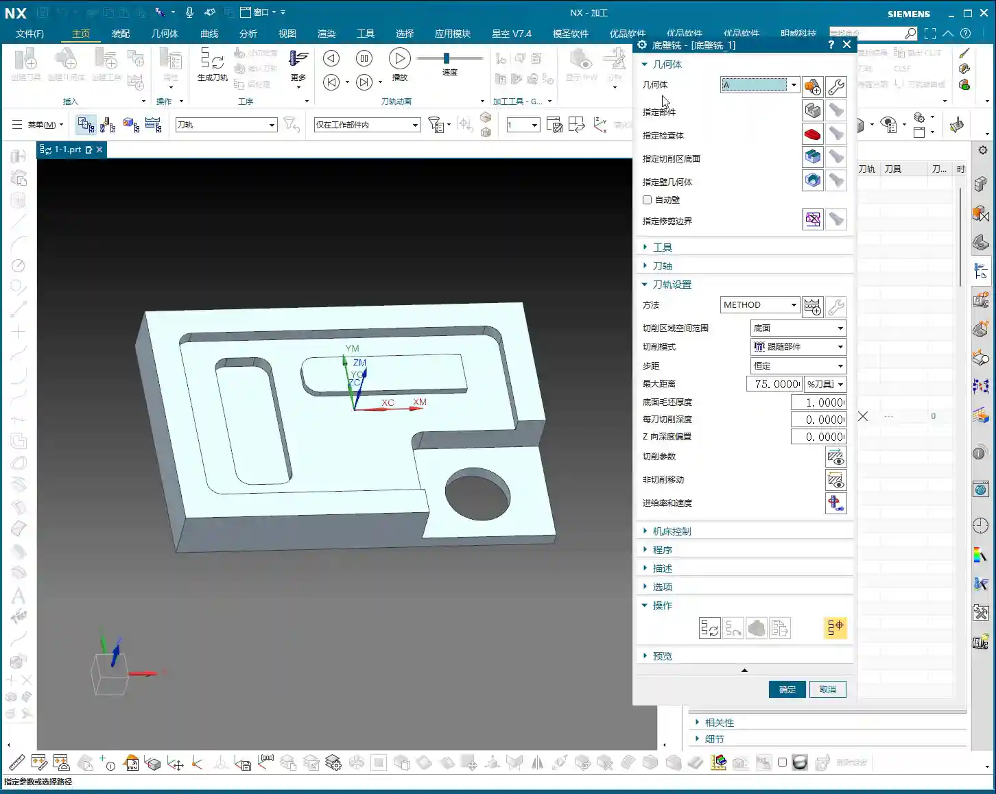
    Listen up, apprentices! Today, we’re going to talk about the core elements that make the machine run in Siemens NX 1980: Feed Rate (F) and Spindle Speed (S). Setting these two parameters incorrectly can lead to minor issues like tool breakage, or major problems like scrapping the workpiece. So, you must get this right!

    In the last lesson, we covered blank stock thickness and depth of cut. This lesson jumps straight to the more critical parts.

    1. S Value: Spindle Speed

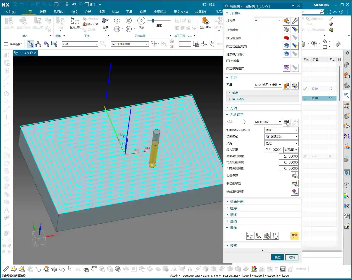
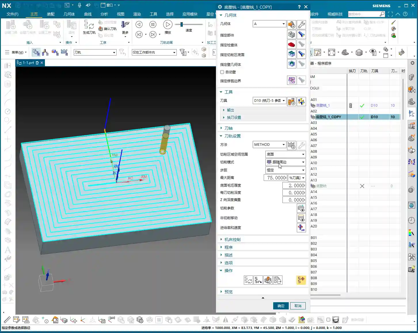
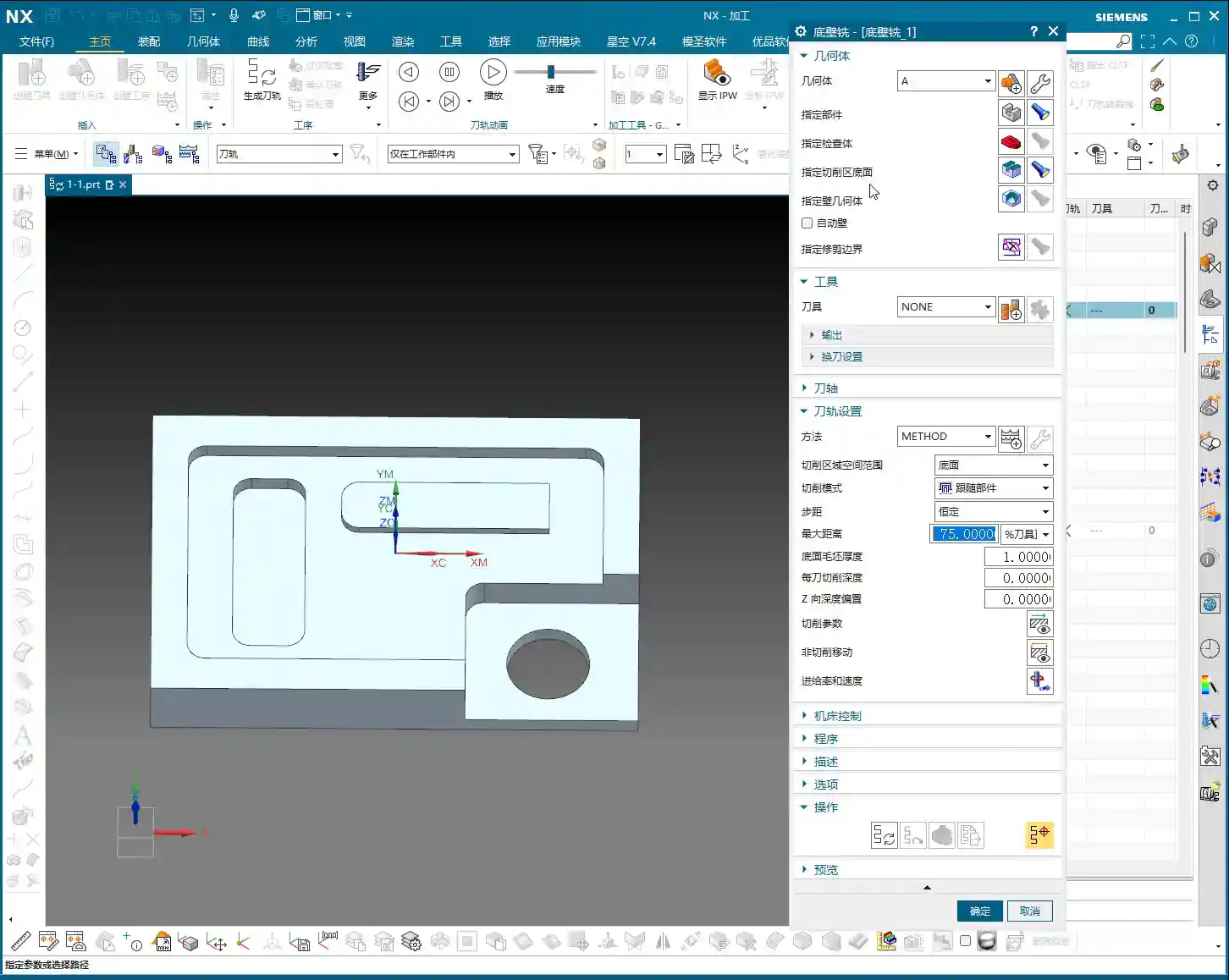
    In the parameter settings, find Spindle Speed. The S value is your spindle’s rotation speed, measured in revolutions per minute (RPM).

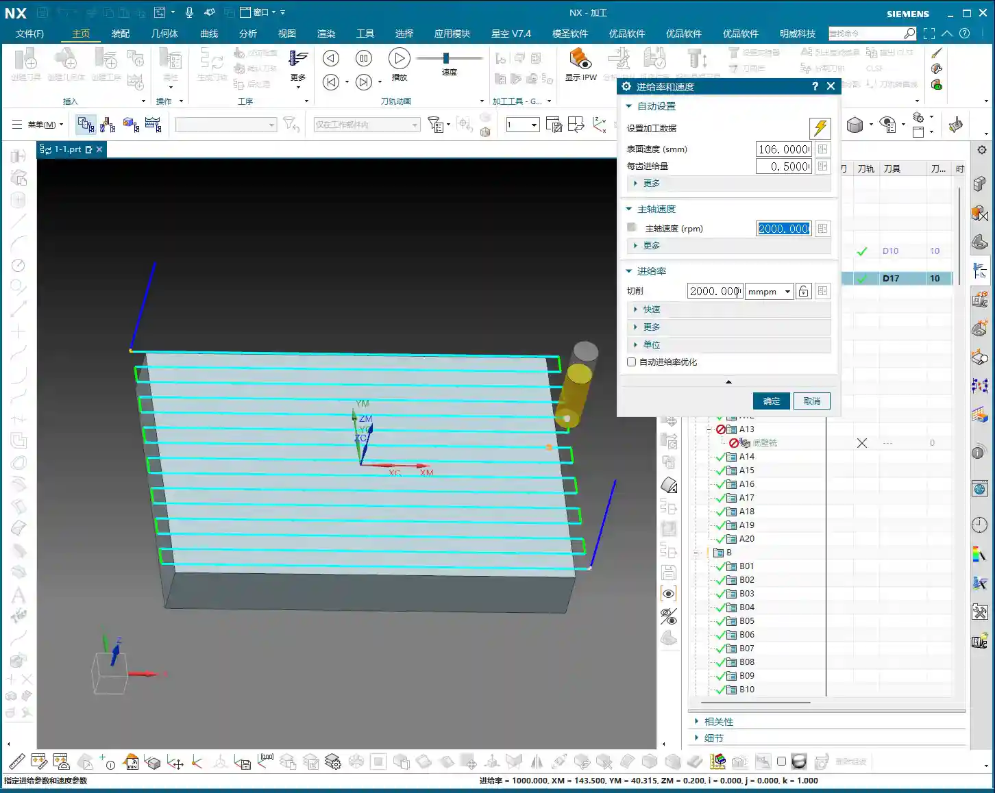
    • How to Set: For example, if the default is S3000, meaning 3000 RPM. If you want to change it to 2000, simply input “2000”.
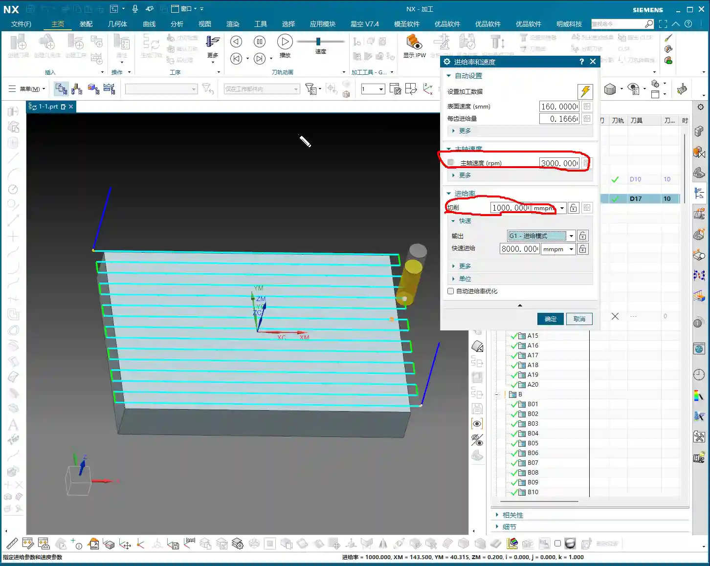
    • Key Reminder: After every modification to the S value, you must click the calculator icon next to it. If you don’t click it, the software might not update, or it might not update completely. As the old saying goes, “Practice without doing is useless, changing without clicking is pointless!”

    2. F Value: Feed Rate

    Once you’ve handled the S value, next up is the F value, which is the Feed Rate, usually in millimeters per minute (mm/min).

    • How to Set: Similar to the S value, directly input your desired number. For example, I’ll set F2000 here. After changing, you still need to click the calculator icon.
    • Modification Tip: Listen carefully! Sometimes if you only change S or F and then click the calculator, the other value might change along with it. The safest approach is to set both S and F values, then click the calculator together. This ensures they both take effect as you intended.

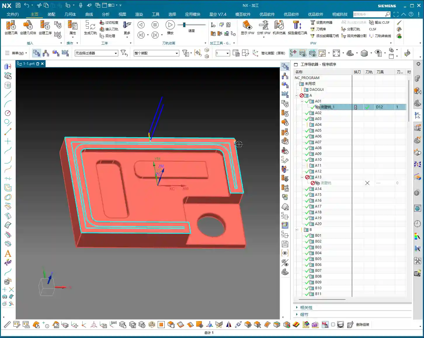
    3. G-code and Feed Rate for Rapid Moves

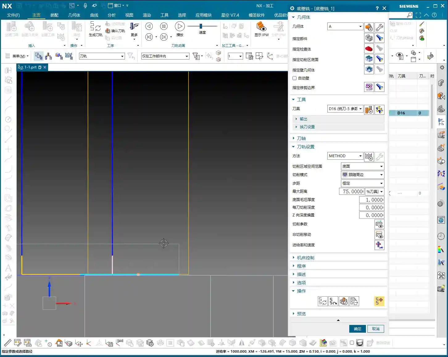
    In the G-code generated by Siemens NX post-processing, G00 stands for Rapid Move, and G01 stands for Linear Interpolation, which is cutting feed.

    • Master Wang’s Template: In my personal template, to avoid the potential impact and uncertainty of G00, I often use G01 for all rapid moves as well, but with a very high Feed Rate, such as F8000. This ensures both speed and smoother movement.
    • Your Choice: You can also set G00 as rapid mode, which doesn’t require an F value input; it will run at the machine’s maximum rapid traverse speed. But remember, G01 is the main cutting command, and its F value is what truly needs to be considered based on material and tool.

    Practical Experience: Spindle Speed References for Different Materials and Tools

    During the programming learning phase, we might start with the software’s default values. For example, my template’s default cutting parameters are roughly S3000, F1000.

    However, during actual machining, you must adjust flexibly based on material properties and tool type. Don’t just rely on software simulations; observe the cutting sparks, listen to the cutting sound, and feel the workpiece temperature!

    1. Master Wang’s “Tool Spindle Speed” Reference Table

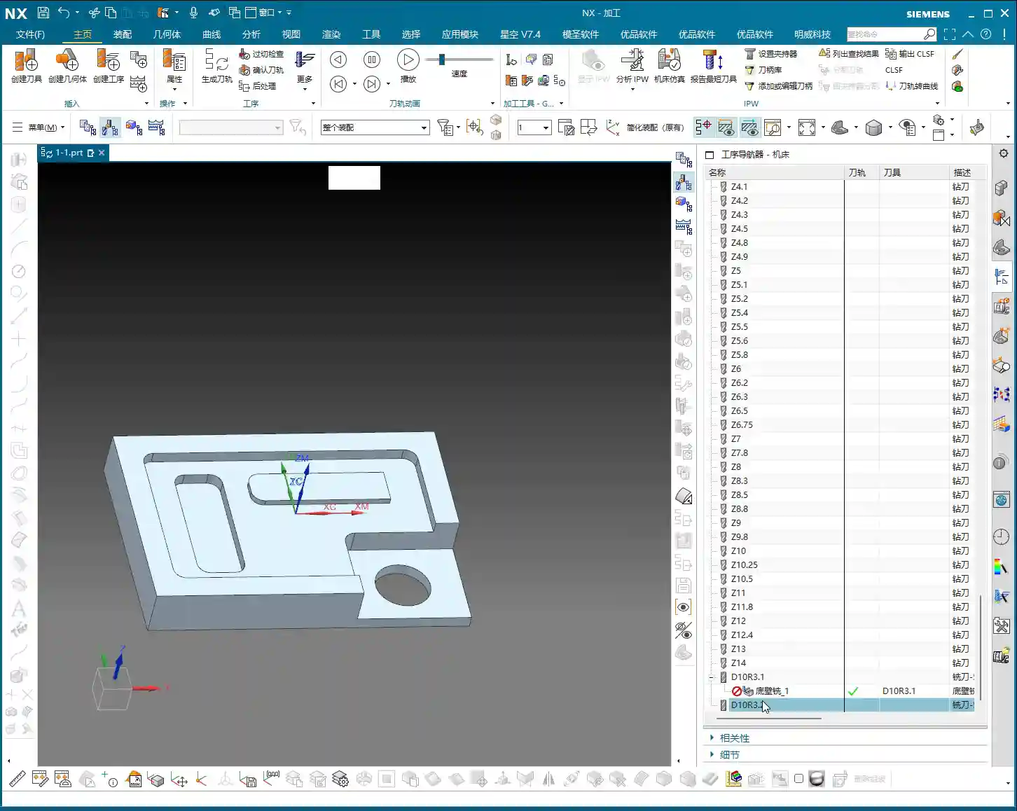
    If you’re completely unsure, you can refer to the empirical data I’ve collected in the “Tools” module. In the Siemens NX menu bar, find “Tools” -> “Tool Spindle Speed”. It’s categorized by Steel, Stainless Steel, Copper, etc.

    I’ll list some common tool spindle speed references for you (for reference only; please adjust according to specific conditions in actual machining):

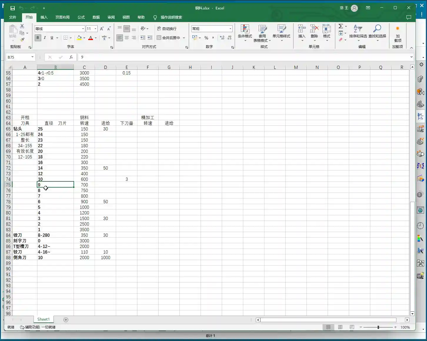
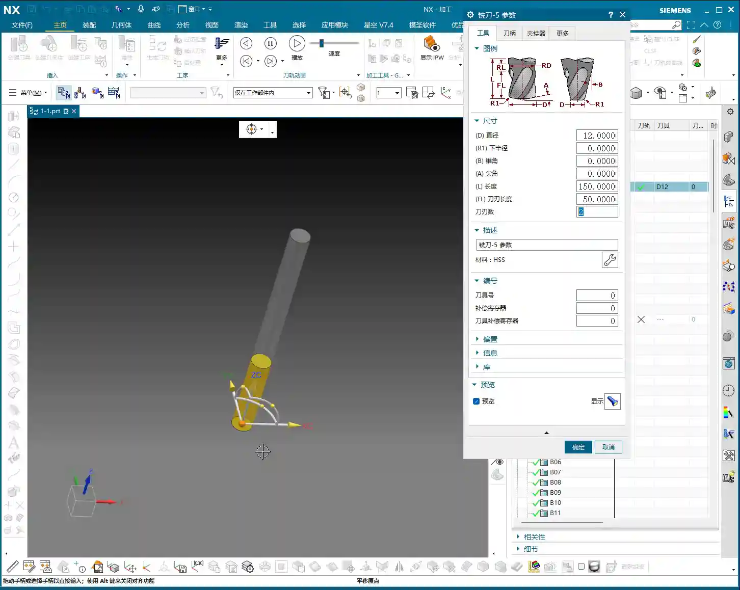
    • Ball End Mill: Varies by size.
    • End Mill:

      • ∅20mm: Approx. S2000 RPM
      • ∅6mm: Approx. S2600 RPM
      • Radius End Mill (e.g., 1R series): Approx. S2500 RPM

    • Drill Bit:

      • ∅9mm: Approx. S700 RPM
      • ∅3mm: Approx. S1500 RPM
      • ∅22mm: Approx. S180 RPM

    2. The “Close Enough” Principle in Practice

    These parameters aren’t rigid rules; they’re merely starting points. For example, if the optimal speed for your tool is actually 2500 RPM, setting it to 2600 RPM is usually fine. As long as it’s “not far off”, the machine and tool have a certain tolerance.

    But remember, the final judgment must come from your experience. Observe carefully and think critically once you’re on the machine!

    Other Siemens NX Interface Parameters Explained

    Many parameters and options in Siemens NX are not necessary to delve into for beginners in programming and daily use.

    1. Parameters to Ignore for Now

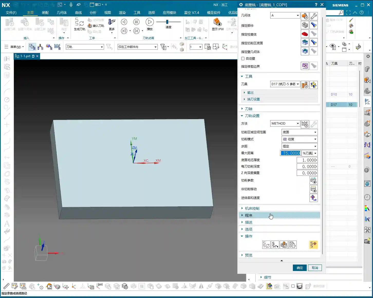
    Things like “Program,” “Description,” “Options,” and some “Links” are not something we need to worry about at the moment. These aren’t very useful for our current programming studies. Once you become an expert, mastering the software, then you can come back and briefly understand what they do.

    2. Parameters for Future Use

    Parameters related to “Machine Control” might not be used now, but they will become relevant when we learn about tool compensation in the future. We’ll explain them in detail then.

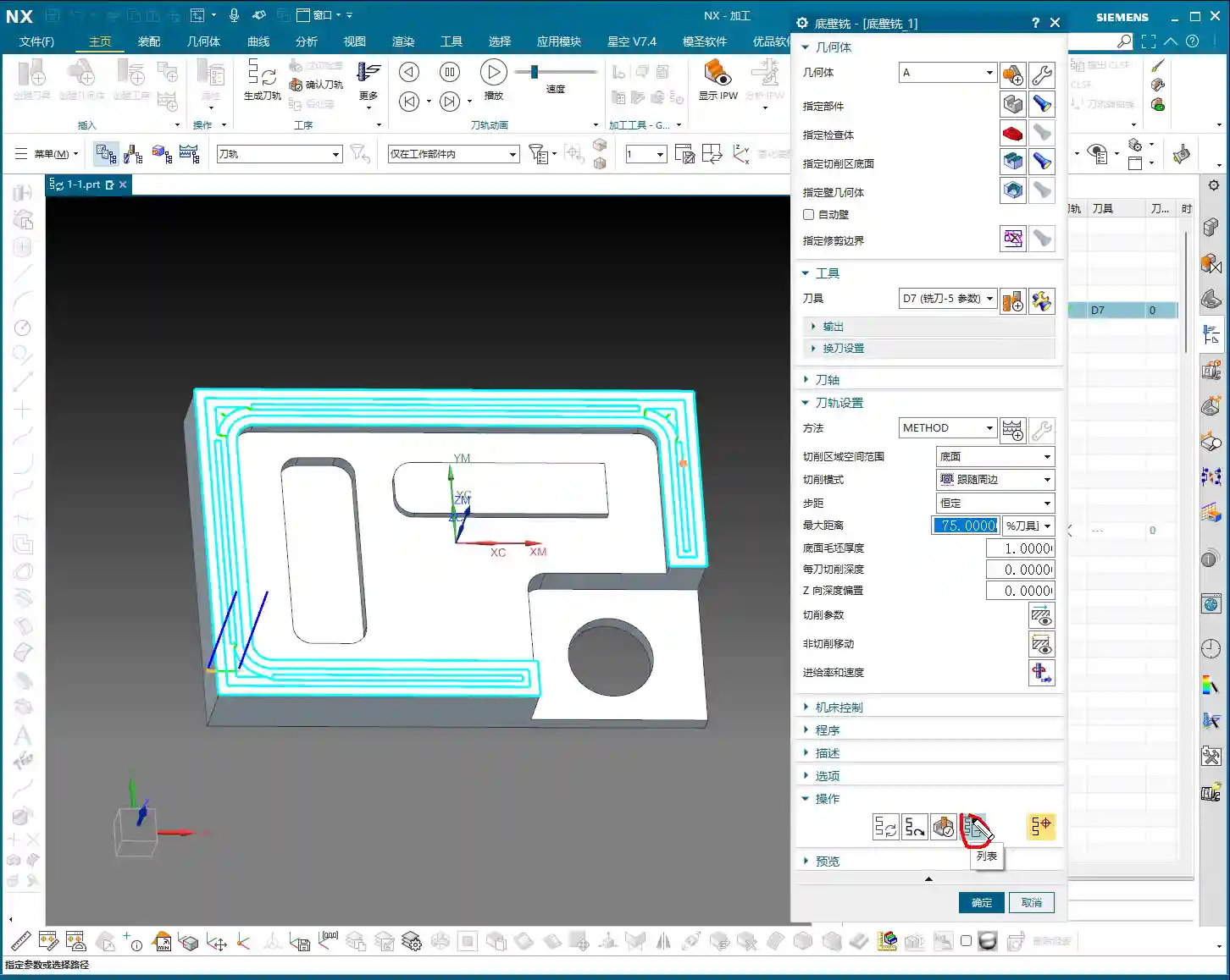
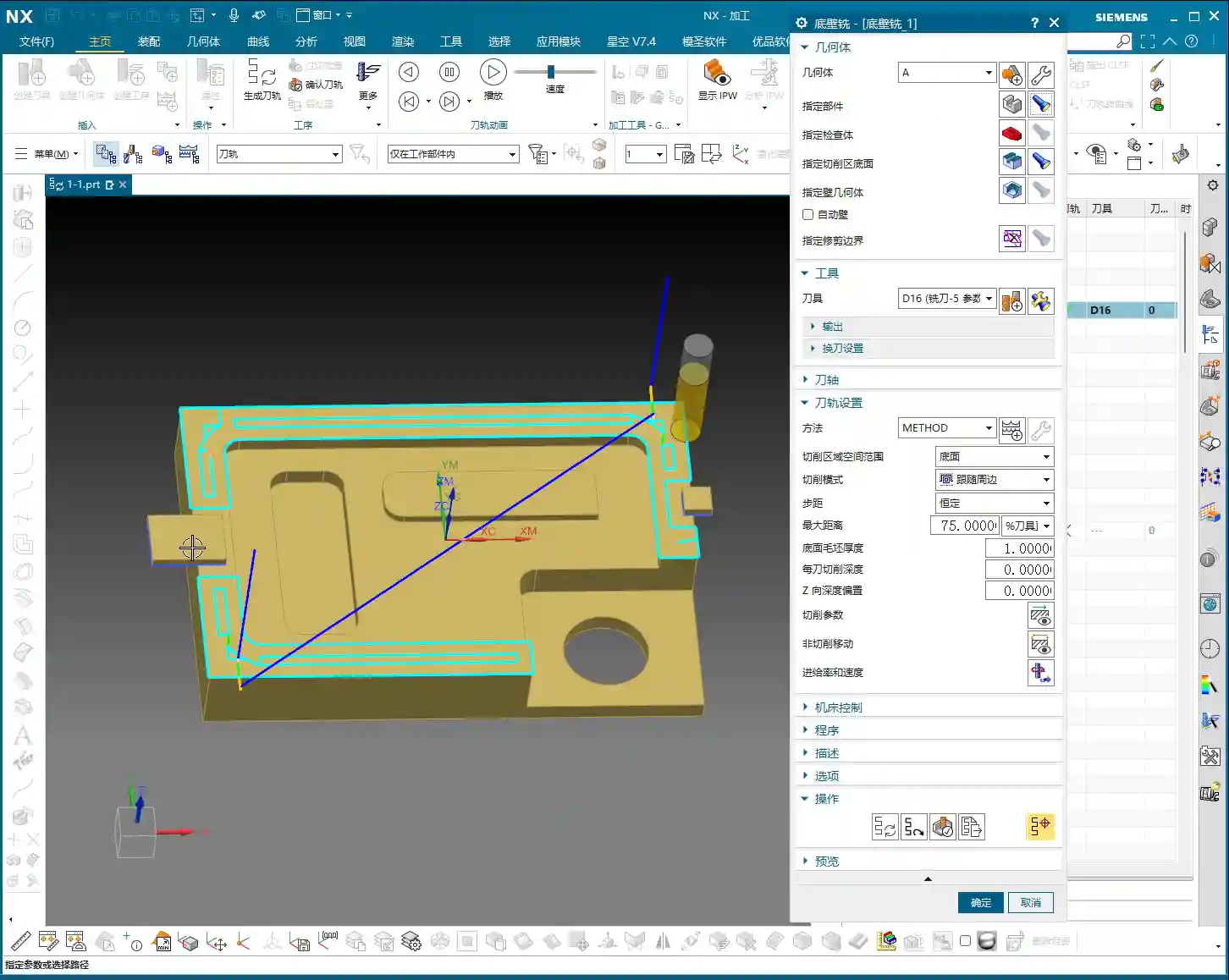
    3. The Essential “Generate”

    The “Generate” command under “Operation” must be clicked after every tool path modification; otherwise, your changes won’t take effect. It’s like an “Execute” button; only after clicking it will the software calculate and update the tool path. You must remember this!

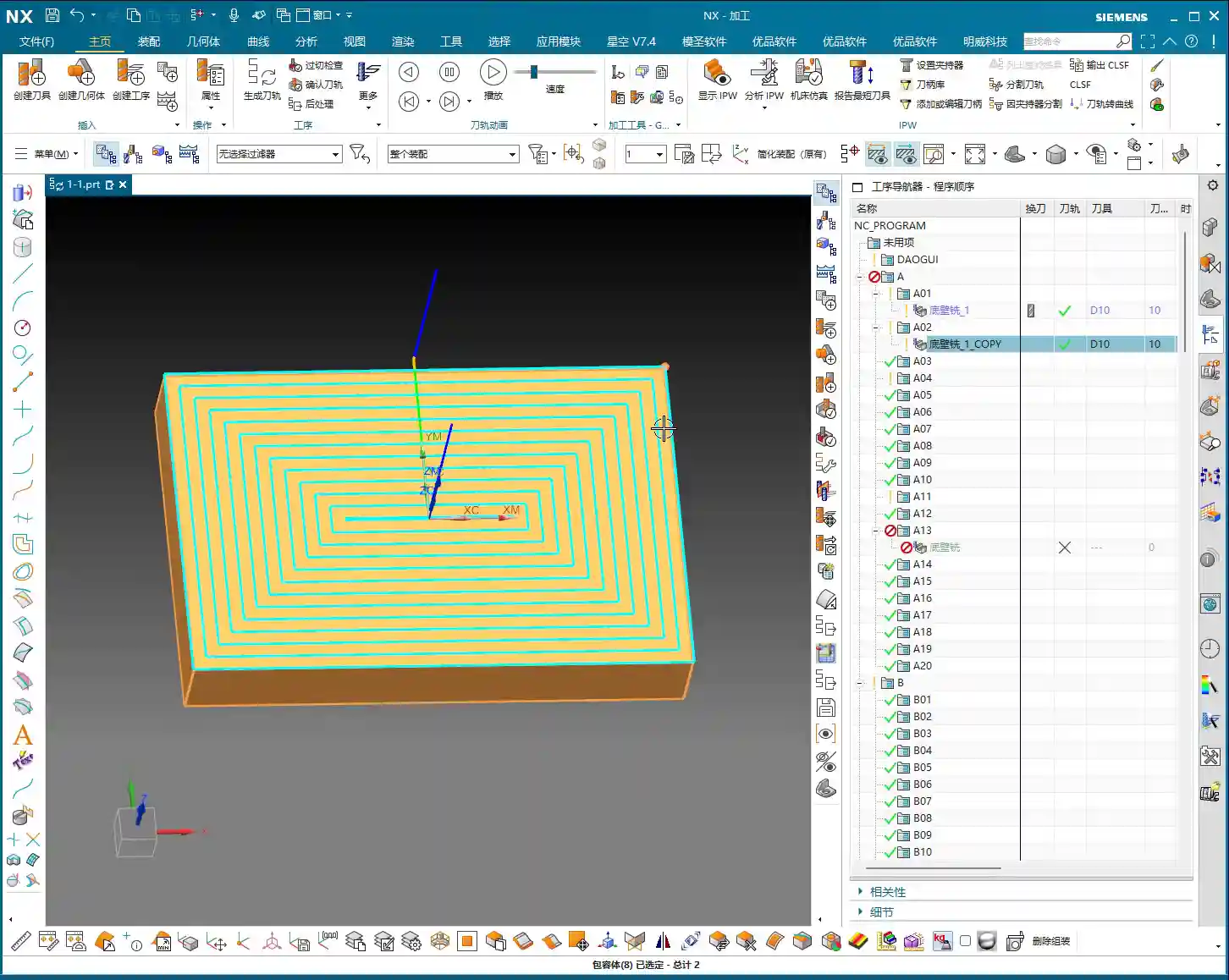
    4. Preview: Just to See the Tool Path Shape

    The “Preview” function is mainly for you to see what the generated tool path looks like. It’s the same visual effect you see on the interface after clicking “Generate.” So, usually, there’s no need to specifically click it.

    Summary: Pitfall Avoidance Guide

    • Core Parameters: S value (Spindle Speed) and F value (Feed Rate) are of utmost importance. Understand and set them correctly.
    • Setting Technique: After modifying S and F values, be sure to click the calculator icon. It’s best to modify both S and F, then click it once.
    • Practice is King: During programming practice, you can use default or reference values. But in actual machining, you must adjust flexibly based on material, tool, machine, and on-site feedback. Don’t be rigid. Master Wang’s experience table is just a reference, not gospel!
    • Don’t Over-Analyze: For parameters not currently needed (e.g., program, description, options, links), just understand their general meaning. No need to waste time delving deep.
    • Key Operation: After every tool path modification, always click “Generate” to update the tool path.

  • UG NX 1980 Tool Axis and Cutting Method Explained

    📝 Key Takeaways: Master Wang gives you an in-depth look at the core functions of ‘Tool Axis’ and ‘Cutting Method’ in UG NX 1980. From basic concepts to practical applications, learn how to precisely set the tool axis direction, master different cutting methods, avoid common filter pitfalls, and ensure efficient, stable machining paths.

    Hello everyone, I’m Master Wang. Today, let’s continue discussing core operations in UG NX, especially the two key points: Tool Axis and Cutting Method.

    Program and Blank Preparation

    We’ve already covered tools, so today we’ll dive right into hands-on practice. First, we need a part to machine. Listen up, this is our actual component. The initial blank (raw material), I enclosed it directly with a block.

    Select this block, select all, set its position to zero, confirm. When we first cut the blank, it was exactly this size, with the part inside, right?

    First Operation: Face Milling

    For the first step, we need to face mill this surface, which means flattening the top surface. Let’s see how DPM (Direct Path Manufacturing) performs this face milling.

    Double-click to open the program. We can copy a program we’ve made before. For example, copy it into A02, right-click ‘Paste Inside’, and it’s there.

    Blank Selection and Transparency

    Double-click to open. If it prompts you to specify a component, just close it. Specifying only the blank is fine, or you can box-select both. Let’s just select this face of the blank, confirm.

    Some might not understand why the blank appears semi-transparent. That’s because after it’s created, its transparency isn’t very high. To adjust transparency, press Ctrl + J, or click ‘Edit Object Display’ nearby. Drag the slider, and you’ll see the solid blank.

    To better observe the face milling effect, we can hide the part first. Click ‘Hide’, then ‘Invert Display’, and the part will be hidden.

    Double-click to open again. When specifying the component, we’ll select the top face of this newly created block blank, confirm. Once the blank and tool are selected, the program should appear, right?

    Toolpath Display and Filter Application

    Pause the program. Now you can click anywhere on the toolpath, and it will jump to that position. Why can you click anywhere? Because our filter is set to ‘Toolpath’.

    If you’re on the current page and click the program, it will be displayed; if you click other folders, then this toolpath will be hidden. So, click the toolpath you want to see, or click upwards, any will select it.

    But pay attention: if your filter is set to another type, like ‘Drafting Filter’, you won’t be able to click on the toolpath. Only when the filter is ‘Toolpath’ or ‘No Selection Filter’ will you be able to click on it.

    Three Highlighted Key Points

    Also, these three areas, everyone must pay attention: they must be highlighted. If the middle one isn’t highlighted, you won’t be able to click the toolpath; if the two at the back aren’t highlighted, your rapid move lines or the entire toolpath will disappear, and you won’t see them at all. Usually, all three are highlighted, which ensures you can view and operate the toolpath normally.

    Tool Axis Explained

    Let’s double-click to open and look at the ‘Tool Axis’ below.

    Default Tool Axis: Perpendicular to First Face

    Currently, the tool axis here is ‘Axis perpendicular to first face’. Why? Because for operations like Floor Wall Milling, its default tool axis is perpendicular to the first face. Usually, we don’t need to change it.

    Common Tool Axis: +ZM Axis

    Generally, during normal machining, it’s mostly the +ZM Axis. Except for Floor Wall Milling, most other commands, ninety-nine percent, use the +ZM axis.

    The meaning of this is that our tool axis is upwards, meaning the Z-axis is upwards, machining from top to bottom. This is how +ZM axis machining works.

    When learning 3-axis machining, it’s basically all about the +ZM axis. Almost all programs are like this. However, for special cases like Floor Wall Milling, setting it perpendicular to the first face is also acceptable.

    When to Modify Tool Axis

    Everyone should now understand the meaning of the tool axis. We mainly need to change it when learning 4-axis or 5-axis simultaneous machining. For 3-axis machining, we generally don’t need to adjust it much.

    Cut Region Space Range: Bottom Face

    Let’s look further down at ‘Cut Region Space Range’ and ‘Bottom Face’.

    Looking at this diagram, there’s ‘Bottom Face’ and ‘B’. I personally think this ‘B’ method is used quite rarely. Because when we later learn 3D machining, we can directly machine sloped surfaces like this. This ‘B’ is specifically for machining sloped surfaces.

    Floor Wall Milling is typically for 2D machining. While it can occasionally machine 3D (sloped surfaces), I don’t think the results are particularly good. So, I don’t really recommend using this function. Everyone just needs to know that such a function exists.

    Typically, we will choose Bottom Face. This way, it directly machines up to this edge, and sloped areas are not machined.

    Cutting Method Explained

    Moving on, let’s look at our ‘Cutting Method’. Currently, the default is ‘Follow Perimeter’.

    What does ‘Cutting Method’ mean? Simply put, it’s the way the toolpath moves. Let’s change it to ‘Follow Part’ and see if there’s any change. For our simple face milling, there’s actually no change.

    However, if we change it to Contour, then there will definitely be a change. ‘Contour’ mode only machines contours. Since we are currently face milling, it’s not applicable, and it will give an error: ‘This component cannot perform face cutting on a planar surface’. So, face milling definitely cannot use ‘Contour’ mode.

    One-Way Cutting

    Let’s try One-Way. One-way is definitely possible. See? It engages the tool from this side, moves to that side, then lifts the tool and returns, then engages the tool from that side and moves back. This is a one-way machining method: move across, lift tool and return, move across again, lift tool and return again.

    Zig-Zag Cutting

    Since you understand one-way, Zig-Zag is even easier to grasp. It just moves across, then directly down, then across again, then down again. That is: move across, go down, return, then move across again, go down, return. It just keeps milling like that.

    This, then, is our ‘Cutting Method’.

    Summary: Pitfall Guide

    Everyone must pay attention to the filter settings, especially when you’re first practicing; not being able to click toolpaths is often because the filter isn’t selected correctly. Furthermore, the tool axis usually doesn’t need to be changed in 3-axis machining, mainly focus on the +ZM axis. The choice of cutting method depends on the type of machining; for example, face milling usually selects ‘One-Way’ or ‘Zig-Zag’, while ‘Contour’ mode is not suitable for planar cutting. Understanding these will greatly improve your programming efficiency and machining stability.

    Alright, we’ll finish this lesson here. We’ll continue in the next lesson. Thank you all for watching, goodbye!

  • Master Wang’s Practical Guide: Siemens NX 1980 Tool Management – Selection, Creation, and Parameter

    📝 Key Takeaways: In this hands-on tutorial, Master Wang shares his expertise on tool selection, creation, and parameter configuration in Siemens NX 1980. Learn how to efficiently manage your tool library, set tool numbers, compensation numbers, and cutting lengths to avoid common programming errors and boost machining efficiency. Practical knowledge you can apply immediately!

    Previous Review and Function Overview

    Hello everyone, I’m Master Wang. Let’s pick up where we left off. We’ve already covered all the functions in that first section. As for “Trim Boundary” and “Specify Boundary,” these aren’t used very often, so we’ll just briefly touch upon them for now and might revisit them later.

    Listen up! Pay special attention to the “Specify Bottom Boundary” function. Frankly, I don’t particularly recommend using it, but since it’s in the software, we still need to know how to use it to avoid potential pitfalls later on.

    Core: Tool Selection and Generation

    Tool Selection

    Look at this section, the “Tool” option. It’s straightforward: choose the tool you want to use. For example, if the default is a D16 (16 mm diameter) tool, we can switch to a D4.7 R0 tool (4.7 mm diameter, 0 corner radius).

    Remember these three crucial steps:

    1. Specify Blank

    2. Specify Cut Area

    3. Select Tool

    As long as you get these three steps right, you generally won’t make major mistakes. Don’t just rely on software simulations; you need to observe the actual cutting sparks and results!

    Importance of Program Generation

    After selecting the tool and setting the parameters, the most important step is to click the “Generate” button. Once you click it, the program will generate the toolpath for you.

    Let me give you an example. Say you change the tool from D4.7 to D5.8. After making the change, the tool in your toolpath might still be using the D4.7 parameters internally. You must click “Generate” for your changes to be truly applied.

    This “Generate” step is the most critical one every time you modify parameters. You can either change all parameters at once and then generate, or change one step and generate. Either way is fine. But any change requires generation!

    We’ll talk about “Replay,” “Verify,” and “List” later. But the importance of “Generate” outweighs them all.

    Methods for Tool Creation

    Method One: Copy and Paste

    If the current tool library doesn’t have the tool you need, like a D17 tool, don’t rush to search for it. We can “Copy” an existing tool and then “Paste” it.

    Next, double-click the pasted tool, rename it to “D17,” and confirm. Just like that, a new D17 tool appears in your tool library.

    Method Two: New Tool Creation

    Besides copying and pasting, we can also directly click “New” to create a tool. For example, let’s create a D10 R3.1 tool.

    Pay attention: If you try to create a D10 R3 tool, and your tool library already has one with that name, you won’t be able to create another tool with the same name. So, it’s best to use a distinct name, such as adding a prefix like “E10 R3.1” to avoid conflicts.

    Simply enter the name and corresponding parameters, such as diameter D10 and corner radius R3.1, then confirm. The new tool is now created. This is effectively the same as copying, pasting, and renaming. Both methods work, use whichever you find more convenient.

    Method Three: Create within an Operation

    When creating an operation, there will also be a “Create Tool” option. This function is identical to the “New Tool” option mentioned earlier. You only need to learn one tool creation method; there’s no need to master every single one.

    So, in summary, you can create tools either externally via “New” or “Copy and Paste,” or directly within an operation. All methods are viable.

    Modifying Tool Parameters and Output Settings

    Editing Tool Parameters

    Click “Edit Display” to modify tool parameters. However, there’s a pitfall here: if you directly change the name or diameter, for example, changing D10 R1 to D11 R1, the tool’s name in the list will still show D10 R1, but its internal parameters will have changed. This is highly confusing, and I do not recommend doing this!

    What I suggest changing here are only the physical dimensions of the tool, such as “Tool Length” and “Cutting Length.” For instance, changing the tool length to 150mm and the cutting length to 50mm is perfectly fine. As for the “Number of Flutes,” you can change this, but usually, it doesn’t have a significant impact if left as default; the software’s default is often sufficient.

    So, after modifying these physical dimensions, the tool’s name in the list will remain the original D12, but its actual dimensions will have changed according to your input.

    Output Settings and Post-Processing

    Next, let’s look at the “Output” options. Here we have “Tool Number,” “Compensation,” and “Length Compensation.” By default, they are all set to 0.

    What do these mean? Simply put, they relate to the G-code generated during post-processing. For example, your G-code might contain M6 T1 (tool change to tool 1) or G43 H1 (length compensation 1).

    Your “Tool Number” corresponds to that T-number. If you set it to 1 here, then in the post-processed program, this tool number will be T1. If your company doesn’t have strict requirements, or if your workshop, like ours, uses non-standardized tools where operators manually perform tool offsetting and input compensation, then setting this to 0 is also acceptable; the operator will fill it in manually.

    However, if you need the program to automatically output T1 H1, then set all three parameters (Tool Number, Compensation, Length Compensation) to 1, then “Generate.”

    Listen up! Changing these parameters here won’t show any visual change in the toolpath within the software. Where do you see the effect? Only when you post-process the G-code! For example, if you select post-processing and then view the generated NC file, you’ll find codes like M6 T1 or G43 H1 inside.

    Summary: Pitfall Guide

    • Always “Generate”: Any modification to tool parameters (diameter, length, compensation, etc.) must be followed by clicking “Generate” to take effect. Otherwise, your program will still be using the old parameters. This is the most common mistake, so remember it!
    • Be Cautious with “Edit Display”: Do not use “Edit Display” to change the tool’s “name” or core identifying parameters like “diameter/corner radius.” This only alters internal parameters and not the displayed tool name in the list, which can lead to extreme confusion. For such changes, please use “Copy and Paste then Rename” or “New Tool Creation.”
    • Understand Tool Number and Compensation: If your workshop’s tool management is flexible and operators manually touch off tools and input compensation, then you can set “Tool Number,” “Compensation,” and “Length Compensation” to 0 in the software. However, if you need the program to automatically output these, you should set the corresponding values. Remember, these changes are only reflected in the G-code after “Post-processing.”
    • Master Multiple Creation Methods: Learn the two primary methods: “Copy and Paste” and “New Tool Creation.” They are essentially the same, so choose whichever you prefer.

  • Mastering UG NX 1980 Milling: Practical Guide to Specifying Part, Check Body, and Cutting Area Botto

    📝 Key Takeaways: Master Wang shares crucial tips for setting ‘Specify Part,’ ‘Check Body,’ and ‘Floor of Cut Area’ parameters in UG NX 1980. From theory to hands-on practice, learn to avoid common beginner mistakes and achieve efficient part machining. Don’t just rely on software simulations; pay attention to the cutting sparks!

    Introduction: Starting with Operation Creation

    Hello everyone, I’m Master Wang.

    Today, we’re going to talk about some parameters within the Floor_Wall (底壁洗) operation and how to create a program. First, let’s take face milling as an example; we’ll mill it once. Then, we’ll process this program.

    Alright, first, when we click, for normal operations, we usually right-click and insert an operation.

    Of course, you can also click the ‘Create’ button. Down here, one is to create geometry, another is to create a tool, one is to create a tool path, this position is for operation inspection, and this position has ‘Create Operation’. This one is ‘Create Program’. Have you noticed these few? They are all for creation.

    So, we can directly click ‘Create Operation’. However, for this step, the program’s location isn’t necessarily fixed to be in A01. For example, if you want it in A10, or say A13, right-click and insert; it will definitely be inside A13. See? When you click ‘Create Operation’, open it, it defaults to what you created last time, so it’s A13. If you want to change it here, it’s a bit troublesome. A is fine, but if you want to create it under F, F-something, it gets a bit cumbersome below. That’s why I generally don’t click that way; I directly click ‘Create Operation’.

    I usually insert by right-clicking, selecting ‘Insert’, then ‘Operation’. This inserts it directly.

    Operation Template and Basic Parameters

    The one at the top, as mentioned, is a template. Select the Floor_Wall (底壁洗) template. This is a Floor_Wall operation. We’ll mainly study the detailed parameters of this Floor_Wall operation to understand what they truly mean.

    This position is Program (程序). What does this mean? Simply put, it’s where we create it, for example, within A01. For Tool (刀具), you can select the tool now. Of course, we don’t need to right now; we can select it later. You can select it in a bit.

    Geometry (几何体) refers to the A-sequence geometry we created. Remember the A-sequence? We created it as a four-sided square, with the top face as zero. This is a coordinate system, essentially the coordinate system on the machine tool. Inside, there’s only A. We’ll discuss A-1 later.

    Uh, for example, at this position, let’s create a geometry. I’ll just create a ‘B’ randomly; I haven’t changed anything. Okay, let’s move it below it.

    For B, if you right-click, insert an operation, then B will appear here. You can choose B or A. However, I didn’t make any changes to our B just now, so B won’t work. We’ll still choose A.

    Similarly, we can delete this B. Right-click, delete. Good. Right-click, insert operation. If you select the geometry, it defaults to A.

    For Method (方法), it doesn’t matter; we won’t discuss methods, so it doesn’t need to be changed. Just select the default here; no matter what it is, the default is fine. The main thing for this page, let’s take a look. The primary thing is that you must select this correctly. Whichever one you want to use, select it. After that, for this, we usually right-click and insert, and it automatically jumps to this; this also doesn’t need changing. This also doesn’t need changing. The only thing to pay attention to is this geometry. Check if the coordinate system you want to use is indeed this one. If it is, then there’s no problem. If it is, you just need to select the sub-program type.

    Alright, first, for this page, we actually change very little. Directly click it, then click ‘OK’.

    Core Parameter Details: Specify Part, Check Body, Floor of Cut Area

    Geometry: Crucial for Selecting the Correct Coordinate System

    This will bring up a dialog box. Let’s see what it actually means, from start to finish. Let’s talk about it from start to finish.

    Geometry (几何体). Alright, there’s ‘Geometry’ here, A. This is the A we are currently using. Of course, you can also change it here. As I just said, this is the same as the A we first encountered. You can also change it, you can change it to B or something. Of course, I deleted that B earlier, so now there’s only A. Usually, this is something we don’t need to change. We already selected it correctly earlier, so no changes are needed. Everyone just needs to understand this. For example, if you selected incorrectly, you can change it again here. This is what geometry means.

    Specify Part: Telling the Machine What to Process

    Specify Part (指定部件). Alright, this is very important. Look, ‘Select Edit’, ‘Select or Edit Part Geometry’. What does this mean? This is very important.

    To put it plainly, in simple terms, ‘Specify Part’ means to designate the part we want to machine. You can select the whole thing, or if you want to machine a specific area, you can just select the entire solid, or just a part of it. For example, ‘Specify Part’, typically, I just click it, then ‘OK’. Selecting the entire part means our component looks like this. You tell the software, ‘My part looks like this.’ Okay, click ‘OK’ directly.

    Alright, this is what ‘Specify Part’ means.

    Of course, there are many options within ‘Specify Part’. For example, click in here. At this position, there’s solid, sheet. We can also choose ‘no selection filter’. If you don’t want it, for example, if you made a wrong selection earlier, you can just cancel it. Or you can directly select our sheet body, or ‘no selection filter’, just select it directly. It’s all fine. There are no issues.

    Specify Part. This is ‘Specify Part’. If you specify it incorrectly, cancel it, then re-specify. Usually, if you specify it this way, there are generally no problems. Filter, you can filter it. Hold down the left mouse button, and since there’s only one solid and no faces, we can just select everything directly. Okay.

    Of course, this list might not be open; you need to open it. There’s nothing else worth looking at. We can just click ‘OK’.

    This tells the software what our part looks like. Alright, now you understand ‘Specify Part’, right? It means specifying the part we are machining.

    Specify Check Body: Avoiding Clamps and Obstacles

    Specify Check Body (指定检查体). What does this mean? This means, for example, let me give you an example first.

    At this position, if there’s a clamp plate, if there’s a clamp plate at this position, for instance, a clamp plate here. We’re only talking about the usage of this tool here, not whether it’s reasonable or not. Whether it’s reasonable, that’s another matter. So, for example, if there’s a clamp plate here, and another clamp plate here. Then, ‘Specify Check Body’ means that we can set that clamp plate as a Check Body. That’s also possible.

    If the clamp plate is set as a Check Body, the tool path will not go over the clamp plate we drew ourselves.

    Let’s draw one here. We’ll wait a moment for this; let’s first see if the program can be generated, and then we’ll draw it. Alright, the meaning of this is roughly what I just said. Let me briefly explain ‘Specify Check Body’. Typically, we don’t use this very often; it’s not frequently used.

    In general, when I use it, if there’s a clamp plate, I usually select it as part of the Part (部件). If you select it as a Part, it won’t machine that clamp plate. This is also a valid approach.

    Specify Floor of Cut Area: Defining the Machining Range

    Specify Floor of Cut Area (指定切削区底面). What does this mean? It means whichever position you want to machine, you select that position. For all of these, you click this position. This small display means that if you click the left mouse button, it will show what you previously selected.

    Alright, ‘Specify Floor of Cut Area’, click it. For example, if we want to face mill, we select this face. Actually, this Floor_Wall operation has many functions. If you just select one face like this, it can roughly automatically define and combine the entire large face for you. It will automatically combine it here, and it will machine it. If I selected it incorrectly, I’d click ‘X’ to clear it. For example, if I box-selected just now, that definitely won’t work. All areas would be machined. So, if you selected it incorrectly, clear it, and we’ll re-select this face. ‘OK’.

    Select ‘Part’, ‘Check Body’, ‘Floor of Cut Area’. Alright, what does ‘Specify B Geometry’ mean? Usually, for face milling, we don’t involve B geometry; it’s not needed for B. So, we’ll skip this.

    Next, ‘Automatic B’ is also skipped.

    We can talk about ‘Specify Trim Boundary’ later. Let’s generate this program first.

    To generate the program, we need to ‘Specify Part’, ‘Specify Floor of Cut Area’, and we need to select a tool. Let’s just pick a tool, for example, a 16mm cutter. Alright, at this point, generate and push it down.

    This program is now created. It shows the tool path. It enters the cut from here, then machines, then machines. Alright.

    Of course, this is for finishing this bottom face, not for face milling the large top surface. For example, if we didn’t machine anything and needed to face mill this large surface, we’ll talk about that later. Let’s first explain the general meaning of the parameters here.

    Check Body in Action: Adding a Clamp

    Now let’s draw a clamp. Incremental.

    Alright, for example, go to sketch, then click on this face. Alright, draw a rectangle, for example, at this position. Draw one here. Alright, draw another one from this position, draw it a bit smaller. Finish.

    Then we’ll extrude it in a bit. Alright, extrude it. For example, I’ll extrude it upwards, let’s give it a distance of, say, 5mm. Alright, ‘OK’.

    Summary: Pitfall Avoidance Guide

    • Program Settings: When creating an operation, right-click and insert directly in the Program Navigator to avoid incorrect default locations, reducing subsequent adjustments.
    • Geometry Confirmation: Always check that ‘Geometry’ points to the correct MCS/WCS (Machine/Work Coordinate System) when creating or modifying an operation. This is the foundation of machining accuracy!
    • Specify Part: Clearly tell the software what your workpiece is and which solid or faces to machine. Incorrect selection leads to air cuts or collisions.
    • Specify Check Body: This is a collision avoidance tool. When there are clamps, fixtures, or other fixed obstacles, set them as ‘Check Body’. The toolpath will automatically avoid them, preventing machine crashes and saving on repair costs! For less complex scenarios, you can also include the obstacles as part of the ‘Part’ to avoid them.
    • Specify Floor of Cut Area: Precisely define the bottom of the machining area. For Face Milling or Floor_Wall Milling, selecting the correct face is crucial, allowing the software to intelligently generate toolpaths and reduce manual trimming.
    • Method and Sub-program Type: In most cases, keep these as default. Do not change them unless you fully understand their purpose.
    • Prioritize Actual Operation: Don’t just rely on software simulation results. Observe the cutting sparks and listen to the sounds during machine operation, combining experience to judge if the toolpath is reasonable.
  • UG NX 1980 Floor-Wall Milling Machining: Master Wang Guides You Through Bottom and Side Wall Machini

    📝 Key Takeaways: Master Wang shares practical techniques for UG NX 1980 Floor-Wall Milling, from coordinate system setup to core function analysis, revealing efficient bottom and side wall machining methods, emphasizing flexible application and real-world experience.

    Hello everyone, I’m Master Wang. Today, let’s talk about an old friend in UG NX: Floor-Wall Milling. This function might sound complicated in textbooks, but in our actual work, it’s a Tier 0-level powerhouse. Using it correctly can save you a lot of trouble.

    I. Pre-Programming: Creating and Applying the Work Coordinate System (WCS)

    Listen up! The first step in programming is to handle your geometric properties, which means setting up your Work Coordinate System (WCS). Don’t think it’s simple and overlook it; it’s your foundation!

    1. WCS Creation and Movement

    Let’s create a WCS and move it to the center of our machining. The method is simple:

    1. Click on WCS and set it in the center.
    2. Select point A to confirm.

    We’ve covered this step before. It’s to ensure the program starts correctly. For one workpiece, we usually only need one primary WCS; others are just auxiliary. While you can create countless WCSs, in practice, we typically use only one as the main reference.

    II. Floor-Wall Milling: Core Function Analysis

    Now, let’s get to the main topic. In UG NX 1980, right-click and select “Insert Operation”, then find our Floor-Wall Milling, which usually comes with a specific template, like “Floor-Wall 1988”.

    1. The Essence of Floor-Wall Milling: Efficiently Machining Floors and Walls

    Floor-Wall Milling, as the name suggests, is specifically designed to cut the floor and side walls of a workpiece. It can remove material, and the cutting area, corner radius, and blank thickness can all be precisely defined. Its Tier 0 status comes from its extensive use in 2D machining, offering high efficiency and excellent results.

    2. Overview of Main Machining Modes

    This command can do a lot! I’ve put together a table for you, which I’ll upload to the 3-axis course later. It mainly includes:

    • Roughing Floor: Quickly removes a large amount of material from the floor.
    • Roughing Wall: Quickly removes a large amount of material from the side walls.
    • Face Milling: Used for planar machining; highly efficient.
    • Finishing Floor: Performs a finishing pass on the floor to meet surface finish requirements.
    • Finishing Wall: Performs a finishing pass on the side walls, similar to finishing the floor.

    Don’t just look at software simulations; watch the cutting sparks! These are the most common and proficient functions of Floor-Wall Milling.

    III. Programming Mindset: Flexible Application, Not Rigid Adherence

    Although Floor-Wall Milling is powerful and can even perform corner cleanup, deburring, and chamfering, we can’t use one command for everything. Programming requires flexibility; don’t just follow blindly.

    1. Choose the Right Tool for the Job

    In my opinion, Floor-Wall Milling excels and should primarily be used for Face Milling, Finishing Floor, and Roughing Floor. Other functions like Finishing Wall, while possible, might be better handled by more specialized commands like Planar Milling in the future, potentially yielding better results.

    This isn’t like what some online sources claim, that it can handle nine or ten different machining methods. Those fancy methods are rarely used. We need to leverage its strengths to maximize efficiency.

    2. Adapt to Actual Conditions, Don’t Memorize Blindly

    Programming is dynamic, not static! If you program a part today based on my instructions, tomorrow you might find that the parameters are off when you switch to a different workpiece or machine, and the program won’t run. This is perfectly normal!

    You must understand why each parameter and command is chosen, not just that it must be chosen this way. When you encounter practical problems, you need to analyze and adjust yourself. Even creating auxiliary bodies (like extended faces) to work with commands is perfectly acceptable.

    IV. UG NX Toolpath Type Classification (2D and 3D)

    Finally, let me briefly categorize UG NX toolpaths, which will help you understand where Floor-Wall Milling fits into the overall system.

    1. 2D Toolpaths: Green Indicators, Basic and Common

    Operations like Floor-Wall Milling and Face Milling, which we discussed today, are typically marked in green in the Operation Navigator. They belong to 2D toolpaths, the most basic and common types used in our daily machining operations.

    2. 3D Toolpaths: Advanced and Complex, Finishing Powerhouses

    Further down the list, from fixed-axis surface milling to some advanced finishing functions, these are usually marked in blue or other colors. These belong to 3D toolpaths and are primarily used for finishing complex surfaces or specific shapes, such as operations related to holes, chamfers, and engraving.

    Remember, these classifications are mainly for convenience in understanding and searching; essentially, they all serve the purpose of machining the part. Don’t let these fancy classifications limit your thinking.

    Summary: Pitfall Avoidance Guide

    As the saying goes, “The master leads you to the door, but you must walk the path yourself.” When it comes to programming, the biggest pitfall is rote memorization. What I, Master Wang, have taught today is meant to give you a practical approach, so you can avoid detours in your future programming endeavors.

    The core points are three-fold:

    1. The coordinate system must be precise; it’s the foundation for all machining.
    2. Floor-Wall Milling should be used where it excels, especially for roughing and finishing floors and walls, as well as face milling for planar surfaces.
    3. Always maintain a flexible programming mindset. Adjust parameters based on the actual part geometry, material properties, and machine accuracy, rather than rigidly adhering to fixed settings. When problems arise, think “why” it happened, instead of complaining “why isn’t it working?”

    In the next lesson, we’ll delve deeper into some advanced applications and special handling methods for Floor-Wall Milling. Thanks for watching, and see you next time!

  • Master Wang’s Guide: Analyzing Parts Before Programming in Siemens NX 1980

    📝 Key Takeaways: Master Wang demonstrates essential pre-programming part analysis in Siemens NX 1980. Learn to inspect dimensions, fillets, and slopes to develop robust, efficient machining strategies and prevent costly reworks.

    Hello everyone, I’m Master Wang. Starting from this lesson, we’ll officially delve into Siemens NX programming. Today, let’s talk about how to “see through” a part before programming to avoid detours!

    Step One: Understand Basic Part Dimensions and Raw Material Size

    Listen up! When you get a part, the first thing isn’t to rush to click the mouse, but to “measure its three dimensions”! It’s like knowing your clothes size; machining is the same.

    Measuring Finished Dimensions and Raw Material Size

    In Siemens NX, we need to use the “Measure Entity” function. Click it open, measure the part’s length, width, and height. For this example, the length is 270mm, the width is 180mm, and the height is 40mm. Keep these finished dimensions in mind. At the same time, you need to know the raw material’s size; this determines your roughing stock.

    Master Wang’s Tip: Don’t just rely on the software display. In actual machining, ensure your raw material has sufficient allowance. You don’t want to find out you’re short on material at the machine, or that the allowance is too large, leading to excessive air cutting time!

    Step Two: Detailed Inspection of Part Geometry (Fillets and Slopes)

    After measuring the overall dimensions, it’s time to act like a detective and thoroughly inspect every corner and edge of the part. Especially fillets and slopes, as they directly influence your tool selection and machining strategy.

    Analyzing Fillet Sizes

    We’ll use the “Geometric Properties” function to check fillets. For instance, if your fillet radius is R10, your tool selection needs careful consideration. Using a D20 (diameter 20mm) end mill to machine this fillet is perfectly fine; it will clear it precisely. Of course, a D16 or D10 tool can also be used, as long as the tool diameter is less than or equal to 20mm. But don’t even think about using a D1 tool; that’s just unrealistic. It’ll be incredibly inefficient and you’ll likely break the tool.

    So, the principle of tool selection is: it must be able to reach the desired feature while also considering efficiency and cost. Don’t use a cannon to kill a mosquito, nor a sewing needle to chisel a rock!

    Checking Side Wall Slope (Perpendicularity)

    Slope analysis is extremely important! Open the “Draft Analysis” function and carefully examine the side walls. If all side walls appear green, it means they are all vertical faces (straight walls), without any undercuts or tapers. This simplifies the part, allowing you to machine it directly with a standard end mill, without needing special processes. If you find any areas with incorrect colors, like red, there might be undercuts or sloped surfaces, and you’ll need to consider using ball end mills, tapered tools, or 5-axis machining.

    Remember: understand the part’s “temperament” to prescribe the right treatment, so you don’t get flustered at the machine.

    Step Three: Establish a Standardized Program Management Process

    After analyzing the part, we move on to programming. But programming isn’t random; it needs a method. Especially for beginners, a standardized program management process is crucial.

    Creating Operations in Sequence

    In Siemens NX, right-click on a folder -> Insert -> Operation. Pay attention here: operations must be created in the actual machining sequence. For example, roughing first, then semi-finishing, and finally finishing pass, from top to bottom, outside to inside. You can’t just jump to programming a specific hole because you want to machine it first; that will lead to big problems on the actual machine!

    Imagine this: you still have a lot of raw material on top that hasn’t been cleared, and suddenly you go to machine a small hole. Isn’t that just asking for a tool crash? So, roughing before finishing, outside before inside, face milling before hole drilling – these are fundamental principles. While we can be a bit more flexible during practice, on a real machine, not a single step can be wrong!

    Learning the Practical Use of Each Programming Command

    Our current learning focus is to understand how each programming command is used, such as Face Milling, Planar Profile, Cavity Milling, Depth Profile, Flow Cut, Curve Drive, and so on. Knowing their individual “personalities” and applicable scenarios will allow you to program with ease.

    Remember, these commands are like your toolbox. Understanding the purpose of each tool will make you a true “master operator”!

    Summary: Pitfall Avoidance Guide

    • Blindly starting is a major taboo! Always thoroughly analyze part geometry before programming, including dimensions, fillets, and slopes. Don’t overlook any detail.
    • Tool selection isn’t guesswork! Choose tools rationally based on fillet sizes and side wall characteristics, balancing machining efficiency and cost. Avoid using small tools for large tasks or large tools for small holes.
    • Program sequence is critical! During actual machining, strictly follow the “roughing before finishing, outside before inside” principle for operation arrangement to prevent tool crashes and ensure safe and efficient production.
    • Take detailed notes! Develop a good habit of recording the analysis results and tool selection strategies for each part, building your own machining experience database.

  • UG NX 1980 Geometric View in Machining: Practical Guide to Coordinate System Setup and Pitfalls

    📝 Key Takeaways: Master Wang provides a hands-on guide to the core of Geometric View in UG NX machining: WCS and MCS positioning and correlation. Master practical skills for creating geometric objects, correctly setting reference coordinate systems, and safety planes to avoid common machining errors and ensure efficient and safe production.

    Introduction: The Core of Coordinate Systems in Machining

    Hello everyone, I’m Master Wang. Previously, we discussed creating tools in the Program View and Machine View. Those were the basics, quite straightforward. Today, let’s talk about something more critical – the Machining Coordinate System. Listen up, whether it’s 3-axis or 5-axis machining, workpiece positioning relies on it. Especially in UG (NX), it’s the “foundation” of your machining.

    Distinguishing WCS from MCS

    When modeling, we all know about WCS (Work Coordinate System), which is used for design. But when we get to the manufacturing module, the true core is MCS (Machine Coordinate System). Remember, MCS is the reference for our actual programming and machine execution.

    A part might have many operations, and each operation may target a different machining area. You can create countless MCSs as needed. For example, if you’re face milling this surface or machining that hole, an MCS can be set for each position.

    Step One: Positioning and Adjusting the WCS

    To establish a reliable MCS, you first need to position your WCS (Work Coordinate System) correctly. This is the first step, and it’s fundamental. You can place it at any location you find convenient for operation, such as a corner or a face of the workpiece. There are detailed tutorials in the modeling module. Here, we’ll just click it and confirm its initial position by double-clicking or using the middle mouse button.

    For instance, we place the WCS at the top-left corner of the workpiece, serving as our machining reference zero. This position must correspond to your actual clamping and tool offsetting setup.

    Step Two: Creating a Geometric Object

    In the UG (NX) interface, after accurately positioning the WCS, the next step is to click the “Create Geometric Object” option.

    Meaning and Function of Geometric Objects

    The essence of “Create Geometric Object” is to create a new geometric group object within the Geometric View of the Tool Path Navigator. This geometric group acts like a container for geometric data associated with a specific MCS, such as machining features, boundaries, etc.

    Typically, we use templates with pre-defined geometric objects, such as DB, 3-axis, or 5-axis templates. These pre-set geometries are convenient for quick access. When a template is loaded, it automatically switches to the pre-defined geometric object, like DB.

    Selecting Geometric Object Sub-Types

    Here, you’ll find sub-types like A, B, C, D, etc. Listen up, here’s a practical tip: It’s best to keep your geometric object sub-type consistent with your current program name. If your program is named “A,” then select “A” for your geometric object sub-type as well. This makes management clear and helps avoid errors.

    As for other options, like those dropdown menus with small triangles, don’t worry about them for now. We’ll go into detail when we discuss specific machining processes later.

    Crucial Setting: Modifying the Reference Coordinate System

    After you’ve created and confirmed the geometric object, you’ll enter the MCS dialog box. There are many options here, most of which you don’t need to touch. However, one place you absolutely must change is the “Reference Coordinate System.”

    Discarding the Absolute Coordinate System, Embracing the Work Coordinate System

    By default, the reference coordinate system might be the “Absolute Coordinate System.” This absolute coordinate system is the software’s own center and has no relation to our actual workpiece positioning. Therefore, we must change it to the “Work Coordinate System,” which is the WCS we set in the first step.

    Remember: WCS is the coordinate system you manually place; it is where you put it. MCS, on the other hand, is what you truly need for programming, and it must reference your WCS. When these two overlap, your program will execute accurately.

    Safety Settings: Plane Selection

    In the MCS parameter settings, another important point is the “Automatic Plane” within “Safety Settings.”

    Plane vs. Surface: A Mistake You Cannot Afford to Make

    Typically, especially in 3-axis machining, we need to manually select “Automatic Plane” as “Plane.” Click it, and then specify a plane as the safety plane. Never choose a surface! If you select a surface, your tool retract and engage movements will be chaotic, which could lead to chatter or even scrapping the workpiece! We must specify a plane as a reference for the safety height, for example, a plane on top of the workpiece.

    As for the numerical input that follows, like 100, that’s the height offset for your safety plane. This height is set based on your workpiece’s actual dimensions and safety requirements to ensure the tool safely retracts during non-cutting movements.

    Summary: Pitfall Guide

    • Coordinate System Positioning: WCS is the foundation of machining. Be sure to position it precisely according to your actual clamping setup. Don’t just rely on software simulations; look at the cutting sparks!
    • Geometric Object Naming: The geometric object sub-type should preferably be consistent with the program name for clear management and to avoid confusion.
    • Reference Coordinate System: The MCS reference coordinate system must be changed to “Work Coordinate System,” not “Absolute Coordinate System”! This is a common mistake for many beginners.
    • Safety Plane: In “Safety Settings,” always select “Plane,” never “Surface.” Specify a safety plane and provide a reasonable safety height. This directly relates to the safe operation of the machine; get it wrong, and you’ll be experiencing tool deflection!
    • Practicality First: UG (NX) has many parameters, but you don’t need to understand every single one. Grasp the core parameters, know how to use them, and use them correctly. For the rest, gain experience on the shop floor; practical experience is more important than textbooks.

  • Siemens NX 1980: Practical Guide to Creating and Managing Program Folders

    📝 Key Takeaways: Master Wang guides you through the creation and management of program folders in Siemens NX 1980, helping you avoid naming conflicts and efficiently organize your machining programs with practical, hands-on techniques. No pure theory, just hard-core workshop knowledge!

    Hello everyone, I’m Master Wang. Today, we’re going to talk about a seemingly small but crucial function in Siemens NX – Creating Program Folders.

    Programs and Coordinate Systems: The Core Foundation

    Listen up! In NX, the most important things we need to focus on are “Creating Programs” and “Coordinate Systems.” Other things, like the fourth machining method we touched on in previous lessons, might be used less by beginners, and we’ll delve into them later. But Programs and Coordinate Systems are the bedrock of CNC programming. You must understand them thoroughly!

    I won’t break down every single parameter for you; that would be exhausting, and many aren’t practically used. We’ll just focus on the key points, the most essential and useful information.

    Why Do Default ABCDE… Folders Appear?

    You might notice that whenever you create a new program, a bunch of folders like A, B, C, D, E, F pop up. Why is that?

    Templates are at Play

    These are linked to our templates. I mentioned in the first lesson that when we directly insert from modeling into manufacturing, at this position in the Program and Tool Manager, NX automatically generates these default program folders based on the template. So, if you find they’re missing or fewer than expected, it’s likely because I deleted them during a teaching demonstration, not a system error.

    How to Create New Program Folders

    If you want to create more program folders, or if the system doesn’t have what you need, it’s simple:

    1. Click the “Create Program” button.
    2. In the dialog box that appears, you can enter the folder name (e.g., “B”).
    3. Remember! The Program Location must always be set to NC. This is a golden rule; remember it! Always select NC. It represents the highest level of operation, and all programs should be housed under NC, not nested within other lettered folders. If placed under A, then A becomes its parent, and if A is deleted, everything below it is gone too.
    4. Click “OK” to complete the creation.

    Naming Rules and File Duplication

    When creating program folders, there’s a common pitfall: duplicate naming.

    Why Does “-1” Automatically Get Added?

    When you try to create a program folder with the same name as an existing one (e.g., if “F” already exists and you create another “F”), NX will automatically append a -1 suffix to the newly created folder, making it “F-1,” or even “F01-1.”

    This is a mechanism within the software to prevent file conflicts and maintain uniqueness. It handles it automatically for you, but you need to understand why these suffixes appear.

    How to Avoid the “-1” Suffix

    If you don’t want to see these messy “-1” suffixes, make sure the name you’re using for your new folder is unique before creation. If there’s an existing folder with the same name and you don’t need its contents, just delete it first.

    Organizing and Managing Program Folders

    The organization of program folders is also very important, directly impacting your programming efficiency and project clarity.

    Free Drag-and-Drop and Hierarchy

    In NX, you can hold down the left mouse button on a program folder and drag it around freely to adjust its order or hierarchy. But be careful here:

    • If you drag a folder into the “interior” of another folder, it will become a sub-folder. For example, if you drag A inside B, A becomes a subordinate of B. If B is deleted, A will also be gone.
    • To keep a folder at the top level, you need to drag it to the same level as the NC main heading, not inside another lettered folder. When dragging, pay close attention to the blue highlight that appears; it indicates where the file will be placed. Make sure it stops below NC, not to the right or inside another folder.

    Be Flexible, Not Rigid

    For most regular programming tasks, one top-level program folder (like an “A”) is sufficient to hold all operations, keeping things clean and manageable. Of course, if your project is complex, a tiered management system is better, but don’t over-complicate it just for the sake of it – that’ll just create more headaches.

    Remember, whether you have those extra folders or not doesn’t affect your final machining results. The key is how flexibly you use and manage them.

    Looking Ahead: Creating Operations

    Now that we’ve got program folders sorted, in the next lesson, we’ll truly begin discussing Creating Operations. This is the core of programming; every programming task requires creating operations. We usually don’t just click the “Create Operation” button directly. Instead, we right-click and choose “Insert Operation.” Next time, I’ll start with the DB template and, following my teaching sequence, explain all the contents within the templates clearly.

    There are many tutorials out there, but as long as you follow Master Wang’s approach, I guarantee you’ll be able to get hands-on work done after learning!

    Summary: Pitfall Guide

    • Program Location must be NC: When creating program folders, their location should always be below NC to ensure correct hierarchy.
    • Understand the Auto “-1” Mechanism: If you see names automatically suffixed with -1, it’s because a file with the same name already exists. Either delete the old one or accept the system’s automatic numbering.
    • Drag-and-Drop Organization Requires Caution: When dragging folders, be sure to clearly observe the blue highlight indicating the cursor’s position. Avoid accidentally nesting folders inside other program folders, which can lead to hierarchical confusion.
    • Be Aware of Template Differences: If your NX interface differs from mine, and you find a different number of default folders, it’s because you’re using a different template. My tutorial is based on my template; understanding this is sufficient, no need to overthink it.
    • Practice More, Think More: Don’t be afraid to delete files or change settings. Be bold and try things out. With programming, the more you tinker, the more you understand.

    That’s it for this lesson. Thank you for watching, and see you next time!

  • Master Wang Unlocks UG NX 1980 Machine View Tooling Secrets: Practical Skills & Pitfall Avoidance Guide

    📝 Key Takeaways: Master Wang provides a hands-on guide to leveraging Siemens NX 1980’s Machine View function for precise viewing and management of various tools (face mills, end mills). Learn essential tool parameter settings, quick creation and modification techniques, and how to avoid common programming pitfalls in this practical tutorial.

    Introduction: Tooling Basics Before Programming

    Hello everyone, I’m Master Wang. In our last lesson, we discussed the Program Order View. We’ve already covered those topics, like this specific area here. You don’t need to memorize every single detail of what each function does, but it’s crucial to understand their literal meaning.

    As we delve into programming, you’ll gradually become more familiar with all these various elements, little by little. Eventually, you won’t even need to think about their exact purpose. So, for now, a general understanding is sufficient.

    Core Function: Machine View and Tool Visualization

    Enabling and Understanding Machine View

    This was mentioned before. Let’s look at the option below it, called Machine View. We can simply click on it.

    The main point is that you can see what it means: it displays the Machine View in the Operation Navigator. In essence, it allows you to show the machine and observe how it moves and how the tool operates to machine your part. You can see all the toolpaths and movements.

    However, for our initial learning phase, we haven’t even created a program yet, so this feature isn’t immediately useful. If you want to use it, you would go to Edit, then ‘Load Machine from Library’ to find many different machines. But we won’t go into that for now.

    Understanding the Tool List: Templates and Customization

    What we need to discuss are the items below. You can scroll down; these can be dragged down further. What do all these items mean at the bottom? I believe many of you might already have some understanding and will grasp it quickly.

    This entire section contains all of our tools. Where are our tools located? They are all placed here on the side.

    Why are these tools here? It’s because of the template I created at the very beginning, remember? That template.

    If you wish to add or delete these tools yourself, you need to go into that template to perform the addition or deletion.

    How do you do it? Please refer to my ‘Master Wang’s Template’ tutorial; there’s a ‘Programming Template’ section within it. Go there to see how it’s created.

    In-Depth Analysis of Tool Parameters

    Face Mill E100 Example: Diameter, Length, and Effective Length

    Let’s take a look. The creation method is quite simple.

    Let’s examine what this means. For example, the first one is E100. The meaning of E100, frankly, refers to its diameter.

    Look, if sometimes it doesn’t display, you can click somewhere else, then click on this E100 again, and the tool will reappear.

    The diameter is 100, meaning the entire diameter of this tool is 100 mm.

    At this point, we can double-click to open it, or right-click and ‘Edit’, both work. I’m used to double-clicking to open it.

    Double-click to open. After opening, let’s look at this area.

    The diameter is 100. Clearly, this tool’s diameter is 100 mm. The bottom diameter is 0. These others are also 0; we can ignore them.

    The length is 75 mm. Simply put, the total length of this tool is 75 mm. And the effective length is 50 mm, which means the distance from this point to this point is 50 mm.

    Of course, as you all know, what E100 means is that it’s a face mill, a face mill with a 100 mm diameter.

    Its bottom radius is 0, which means it should typically be E100 R0.8. Usually, the inserts for these tools have a small corner radius of R0.8. So, it’s a tool like E100 R0.8. Why did I set the bottom corner radius to 0? We’ll discuss that later when we get to programming. For now, just understand what this tool represents.

    This face mill has a total length of 75 mm and an effective length of 50 mm.

    You might ask, how can the effective length be 50 mm? Because for insert tools, the insert itself isn’t 50 mm long. The point here is that we can give it an approximate value. You don’t need to create it to be exactly identical to the physical tool. We only need to create the approximate size of the tool, and that’s sufficient.

    Tool Positioning and Machining Simulation

    Now, by default, whenever we open the tool, it will appear in this position. We can click and hold the left mouse button to drag it, or simply click on a specific spot on the screen to place the tool there.

    What is this actually for? Simply put, we can place it, for example, approximately here. Then we can check if a single pass of this tool can cover the entire area. This is the edge, and this is the edge. If it starts cutting from here, moves along, and then comes over, can one pass cover it? Clearly, it can. A 100 mm tool can cover this area.

    Okay, when we reach this position, there’s a significant amount of material here. You also know what this means. It means our tool is too large to machine this corner radius. In such a situation, we would definitely need another type of tool to perform corner cleanup. Just understand this concept.

    We can’t machine all the way to this point, right? If we did, we’d be overcutting this area.

    The purpose of this is simply for reference. It allows us to check if the tool is large enough, or if it’s suitable, if we can use this tool. Just take a look, a rough look. But for the final selection, you also need to check what tools you actually have available.

    You can click anywhere; clicking here or on that corner, both are fine.

    Alright, so this is about how to change or view our tools. Roughly, there’s also the length and effective length. That’s good. Let’s move on.

    Quick Tool Creation and Modification (Critical Pitfalls)

    E-Series Face Mills: Copying, Renaming, and Parameter Modification

    For example, now we have E59, E90, E80, E63, E40. All of these are insert tools (face mills with removable inserts). Any tool starting with ‘E’ is typically an insert-type tool. E25, E21, E20, E17, E16.

    For instance, let’s say we want to create an E15 tool. How do we create it?

    Right-click, Copy. Then directly click Paste. Good.

    Now, this tool and the original one are actually identical. It’s just like copying and pasting any other item, like a folder or anything else. The copied and pasted items will definitely be identical.

    We need to modify the pasted tool. Right-click. Why is there English at the end? Because their names cannot be duplicates.

    For example, for E17, just change the ‘6’ to ‘7’, and press Enter. See, now you have an E17 tool, right?

    Oh, for E15. Right-click, Rename. We’ll take this position, you can drag it a bit, and change it to ‘5’. Okay.

    Can it be used now? We copied it and changed its name to E15. Is this correct? Absolutely not!

    Although its name has been changed to E15, this tool is still a 16 mm tool. Everyone, please, please, please remember this: just renaming the tool’s display name to E15 does not make it an E15 tool. That’s impossible. You must double-click to open it, then go to the Diameter field and enter 15. Good, then press Enter. That’s all. Of course, there are other parameters like tool holder, etc., but for now, we don’t need to worry about them. We just need to make sure the diameter is correctly set. The length and effective length have already been discussed.

    Right-click, OK. Only now is this tool truly an E15 tool. Double-click to open and check again. 15, correct. OK.

    R-Corner Radius Tools: Distinguishing E90R0.8 and E63R6

    Let’s look at the E90 R0.8 below. Actually, this one and the E90 are quite similar. But the R0.8 indicates that at this position, there is a small corner radius. This position has an R0.8.

    Why are these two types of tools so similar? It’s simply my personal habit for future programming; I might need both. We’ll discuss that later. For now, there’s no need to explain it so thoroughly; we just need to understand what these tools mean.

    We also have E63 R6. Everyone knows this type of tool, right? It’s an E63 face mill with an R6 insert. This is an R6 insert, quite large, a round type of insert.

    E63 R0.8 is a square-ish insert.

    These are all self-explanatory, and the differences are quite clear.

    D-Series End Mills: Similarities and Differences with E-Series

    For example, for an E25 R5 tool, we copy it, and then paste it.

    Suppose we want to create an E26 R5. Just create a random one.

    Rename. The first step is to rename it. E26 R5. Delete all the English characters at the end, then press Enter.

    At this point, we double-click to open it. E26 R5. We don’t need to change the ‘R’ value.

    Let’s say, for example, you don’t want to confirm directly now. Suppose you realize you made a mistake with this tool in your work. You can double-click to open it. For example, if you want to create an R4 tool. You change it to 4. You must press Enter. If you change it to 5, you have to press Enter. When you preview this ‘R’ value, for example, if you input 1, press Enter. Okay, now this position is 1. You must press Enter; it’s a habit. Enter. Okay, Enter, Enter.

    R4, Enter.

    Don’t worry about the effective length or anything else; just click OK. But you must rename it from ‘5’ to ‘4’, because you’ve already changed the internal parameters to E26 R4, so the external name also needs to be updated. OK.

    This is a quick way to create a tool. This method of creating tools, I think, is quite convenient; you just copy and paste.

    All tools starting with E are typically insert tools (face mills).

    Now, what about tools starting with D? These are actually end mills. They are not insert tools, meaning they can machine with their side cutting edge as well. I believe everyone has seen this type of tool in the machine shop. You’ve definitely seen them.

    D35 R3 means a 35 mm end mill with an R3 corner radius, very clear. D14 R1.5 means a 14 mm end mill with an R1.5 corner radius.

    For example, how do you create this? The creation method is exactly the same as what we just did.

    Summary: Pitfall Avoidance Guide

    Listen up, Master Wang emphasizes again:

    1. Name vs. Parameters: In Siemens NX, renaming a tool’s display name (label) does not automatically change its actual machining parameters! You must double-click to open the tool properties, manually modify core parameters like diameter, length, and corner radius, then press Enter to confirm, and finally click OK for the changes to take effect. This is the most common pitfall for beginners.
    2. The ‘Approximate’ Rule for Effective Length: For a tool’s ‘effective length’ (or cutting length), especially for non-standard tools or face mills, providing an approximate value that meets machining requirements is sufficient in the model. There’s no need to demand 100% exact match with the physical tool. The software model is mainly for visual simulation and toolpath calculation.
    3. Machine View for Visual Verification: Use the Machine View to visually check if the tool’s size is appropriate, if it can cover the machining area, and if there’s any risk of overcutting. Don’t just rely on software simulation; you need to envision the cutting sparks! While this is virtual, this way of thinking is fundamental to practical machining.
    4. Significance of Corner Radius (R-Value): Understand the meaning of the R-value in tool names (e.g., R0.8, R6). It represents the corner radius of the tool’s cutting edge. Different R-values correspond to different insert shapes and machining characteristics (sharp corner, rounded corner), which are crucial for corner cleanup and contour milling.
    5. E-Series vs. D-Series: Familiarize yourself with common tool prefix conventions in Siemens NX. Typically, ‘E’ series often refers to face mills / indexable face mills (Face Mill) with replaceable inserts, suitable for roughing flat surfaces. ‘D’ series often refers to end mills / ball nose end mills (End Mill/Ball Nose), commonly used for side milling or finish contour milling.
    6. Importance of Templates: Your tool library should be built upon standard templates. The initial tool list comes from your programming template. Learning to manage and customize templates can greatly improve efficiency.

  • UG NX 1980 Process Sequence View Explained

    📝 Key Takeaways: Master Wang is here to guide you through UG NX 1980 3-axis programming! This lesson focuses on the Process Sequence View, showing you how to correctly switch views in the manufacturing module, use the Operation Navigator, and understand how programs run step-by-step. All hard-hitting, practical tips you won’t find in textbooks!

    Introduction: 3-Axis Programming and Environment Switching

    Hello everyone, I’m Master Wang. Starting today, I’ll be systematically covering 3-axis programming, from basic 2D toolpaths to drilling, and then on to 3D machining. This is a complete programming workflow, and we’ll go step-by-step, from top to bottom, to create a full program and deeply understand what each command is used for.

    If you want to review modeling first, you can check out my previous modeling courses. Those courses explain what commands like sketching and extruding do – these are fundamental, and you all need to know them.

    Now we’re mainly focusing on programming. For programming, we usually go to the Manufacturing page. So, just click “Manufacturing” to enter.

    Listen up, the prerequisite is that you must insert my programming template! I already have a template loaded. When we click to enter the manufacturing module, we don’t need to worry about the default options at the top; the third position is the default. For this, we can also default to the DB template. Just click OK. This is the first step, entering manufacturing.

    The Importance of Programming Templates

    At this point, our interface will display some items. The prerequisite is that you must have inserted this programming template. How do you insert it? Look for my “Master Wang Programming Template” link; there’s a video that details where to place the template and how to use it, and even how to create your own templates. That video is straightforward and easy to understand. If you’re unsure, watch it a couple of times.

    In this course, we won’t go into detail about templates; we’ll focus on programming itself.

    Manufacturing Interface Overview and View Switching

    Looking at the manufacturing page, we have the top, left, bottom, and right sections. In fact, these are all small commands. Let’s look at the left side; aren’t these quite familiar? They are actually similar to what we covered in the modeling section.

    Basically, sometimes we will switch back to modeling. Just click this position to switch. Click manufacturing again, and it switches back. Click modeling again.

    Listen up, this is where mistakes often happen!

    Look at the left side: when we’re in manufacturing, doesn’t it look quite similar? However, sometimes, the items in manufacturing are not present in modeling. Manufacturing commands, for example, like creating a geometric body or creating a tool, cannot exist in modeling. Similarly, in modeling, you have commands for creating blocks or cylinders, but these won’t be found in the manufacturing module.

    So, when you can’t find a command, it’s worth switching to the modeling environment to look for it, especially the bottom panel. The bottom panel in modeling has many more options, but in manufacturing, there are fewer, only up to this point. Just these few.

    Therefore, you all can examine it yourselves, especially this particular location, the command area. You can practice switching back and forth to familiarize yourselves with which commands are available where. Once you get used to it, you’ll be fine. Getting accustomed to these commands is key.

    Of course, there are some commands in manufacturing that are not in modeling, and we’ll definitely discuss them. Since this is our first lesson today, we don’t need to go into too much detail. We just need to get a basic understanding of these few commands for now.

    Key View: Operation Navigator

    For the first step, when we’re in manufacturing, this area defaults to displaying the Part Navigator. We definitely don’t need the Part Navigator; we need to switch to the Operation Navigator. Because in manufacturing, what we generally use for programming is the Operation Navigator. You can switch it yourself: this is the Part Navigator, and this is the Operation Navigator. There are constraints and assemblies. So, in manufacturing, we basically always use the Operation Navigator.

    The Secrets of the Process Sequence View

    Alright, once you’ve opened it, do you see? It has this page.

    Regarding the top section, I can’t go through everything one by one right now. We’ll introduce these functions gradually as we go through the programming steps in upcoming lessons. If I were to explain how each one works right now, I believe many of you might not fully grasp it. We need to introduce it bit by bit. However, when we’re just starting, in the early stages, it’s crucial to know how these few are used.

    Also, you need to know how to create a Work Coordinate System (WCS). That’s the G54 WCS. For a machining center, whether we’re datum setting on one side or using four-sided datum setting, you definitely need to know this.

    So, in our first lesson today, we’re mainly talking about these four, these few. This one, and this one, this one, this one – what are they generally used for?

    Basic Programming Operations and Program Sequence

    For some basic skills, like right-clicking, left-clicking, selecting, rotating, moving, and so on, you can refer to the initial lessons in the modeling section to get familiar with them. If you’re just starting and only want to learn 3-axis programming, then I recommend that you at least have some familiarity with UG. You should at least know how to rotate your model, or how to select linked components, or how to deselect components, or how to select just one specific location, like a single face. For these things, I suggest watching our modeling course, especially the first few lessons. You don’t need to watch every single part if you only want to program; it’s not necessary to master everything.

    But at least you should be familiar with these basic operations. For example, if you click here, what happens? Or if you click here, what does it do? You must know these things. I won’t go into detail here. We will mainly focus on programming commands.

    Understanding the Program Order View

    First step, let’s take a quick look at this panel. When the Program Order View is highlighted, this area looks like this. I’ll drag it over a bit; it’s quite long. See? Very, very long.

    This area has a Tool Path, which is actually a folder. You can click it, right-click, and select Insert Operation. This is a normal procedure for us: insert operation. For 3-axis, there are all these commands here. All the commands we need to cover in the future are all in here for programming. For 3-axis, we currently only have 3-axis, so it’s 3-axis. This is 5-axis; if you’re doing 5-axis, watch the 5-axis course. The 5-axis course is almost finished recording. You can just watch the 5-axis course. Of course, if you learn 5-axis, then all these small operations will definitely already be familiar to you. Because if you learn 5-axis, most of the basic 3-axis operations will be covered. So we’ll just look at 3-axis.

    Alright, for example, I’ll just click this command, then OK. I’ll just click OK directly. Take a look. I won’t talk about other things for now.

    To put it simply, this is a program we’ve created. But it’s not actually created yet. We can look at this position. Tool Path, it shows Tool. I haven’t selected a tool yet, but you see, the tool number, that means T0. I’ll briefly explain this; it will definitely be covered in more detail later. For now, we’ll just give a general overview of this command.

    The tool number, which is T0, and then the time, meaning how long this program will take. Alright, let’s just — oh, I clicked the wrong small number. Let’s cancel it. We’ll go through it one by one. Typically, when inserting, we need to insert A. This refers to A-sequence, B-sequence, C-sequence, D-sequence, E-sequence. These tool paths.

    Of course, there was also F, but I think I deleted it. I feel these five are sufficient, so I won’t use F. That is, A, B, C, D, E. These tool paths. When we click the small triangle, the small cross, next to A, it further divides into many: A01 all the way to A20. I don’t know if everyone is familiar with what this means.

    When you’re programming in A01, let’s just, I’ll randomly select one. OK. Alright, this program is numbered A01. Then in A02, for example, we insert another operation and create another program, that would be A02. When we post-process, this program will be A01. When we need to run it, we’ll run A01 first, then A02. This is how the operations are arranged step-by-step, from A01 all the way to, say, A20. It’s about machining these programs sequentially. This is what we’ll be programming in the Program Order View.

    These are just folders, just the names of the folders. You all should have some understanding of this. Alright, I won’t go into excessive detail. Let’s take another look, mainly focusing on this area.

    First, insert an operation, select the DB sequence. For example, I’ll just quickly create a simple program, a very simple program. Click, select this face, select tool. This doesn’t matter; you don’t need to follow me exactly. We just need to understand what this means for now.

    Alright, the program is now generated. We can click the play button to see. Okay, the program is complete. Look at this area: Tool Change, this is T10, indicating we are currently using tool number 10, right here. How exactly is this position found? I’ll drag it back a little further.

    Okay, some of your setups might be different from mine. Right-click, then Columns.

    Summary: Pitfall Guide

    • Environment Switching is Fundamental: You must be proficient in switching between the modeling and manufacturing modules and understand the unique functions of each. If you can’t find a command, first check which module you are in.
    • Operation Navigator is Key: In the UG NX manufacturing module, you must use the Operation Navigator for programming, not the Part Navigator. This is crucial for organizing and managing all machining operations.
    • Understand the Logic of the Program Order View: Sequences like A01, A02, etc., represent the execution order of programs. Plan your operation sequence logically to ensure the machining process meets actual production requirements.
    • Utilize Programming Templates Effectively: Using pre-set programming templates can significantly improve efficiency and standardization, reducing repetitive work. If you don’t have one, make sure to learn how to create or import one.
    • Basic Operations are a Prerequisite: Don’t underestimate the basics. If you are not proficient with fundamental UG NX modeling operations (selection, rotation, movement, etc.), it will directly impact your programming efficiency and accuracy. Master these basic skills first.
    • Pay Attention to Tool Numbers (T-numbers): In the Process Sequence View, each tool has a corresponding T-number. This is a critical reference for the machine tool to identify and automatically change tools, so you must understand its meaning.