Blog

  • In-depth Analysis of Non-Cutting Moves in Siemens NX: Master Wang Teaches You How to Optimize Tool P

    πŸ“ Key Takeaways: Master Wang provides an in-depth explanation of “Rapid Transfer” and “Entry Point” within Siemens NX’s non-cutting moves. He emphasizes how to precisely set safety heights, differentiate between within-region and between-region transfers, and flexibly specify entry points to avoid collisions, significantly reduce air cutting time, and boost machining efficiency, helping junior engineers avoid common pitfalls in practical operations.

    Master Wang’s Lecture: Do You Really Understand Non-Cutting Moves?

    Hello everyone, I’m Master Wang. Today, we’re going to continue discussing those practical tips and tricks in Siemens NX programming that you “won’t find in textbooks.” Where did we leave off last time? Oh, things like smoothing, collision checking, and tool compensation.

    Listen up, for most of our 3-axis work, you can largely set aside or just use the system defaults for parameters like Smooth/Blend Corner, Collision Check, Tool Compensation, and B-spline. These have minimal impact on conventional 3-axis machining and are primarily used in complex 4-axis or 5-axis scenarios, or for specific finishing passes.

    • Blend Corner: This feature primarily smooths tool path corners, preventing sharp turns that can affect tool life and surface quality. However, for standard pocketing and face milling, the default smoothness is usually sufficient. If you’re tackling complex surface finishing where extreme surface quality is paramount, that’s when we’d fine-tune it in specific finishing passes. But that’s a topic for another day.
    • Collision Check: In theory, it’s a good feature, helping you spot issues during software simulation. But on the shop floor, I put more emphasis on your familiarity with the workpiece, fixturing, and cutting tools, as well as your judgment of the machine’s travel limits. A skilled machinist should already have a clear idea before programming: where potential collisions might occur and where it’s safe. This is about proactive prevention, not waiting for software errors to find remedies.
    • Tool Compensation: G41 and G42 are fundamental CNC concepts. In Siemens NX, it primarily manages how tool radius and length compensation are applied. When programming, we typically model according to the workpiece’s actual dimensions, and tool paths are generated based on the tool’s centerline. Compensation is usually handled at the machine control, which is what we call Tool Offsetting or Touching off and measuring tools. The tool compensation parameters in Siemens NX primarily provide an instruction to the post-processor, telling it to output a program with G41/G42. In practice, it’s more about ensuring the post-processor correctly outputs these compensation commands rather than frequently modifying the compensation values within the Siemens NX interface.
    • B-spline Parameters: This relates to the mathematical representation of tool path trajectories. Simply put, it affects the smoothness and calculation precision of the tool path. But for conventional 3-axis machining, Siemens NX’s internal optimization is excellent, so you generally don’t need to worry about this, especially during roughing and semi-finishing stages. Only in very rare cases, such as specific finishing passes requiring extremely high path continuity, would you need to adjust it.

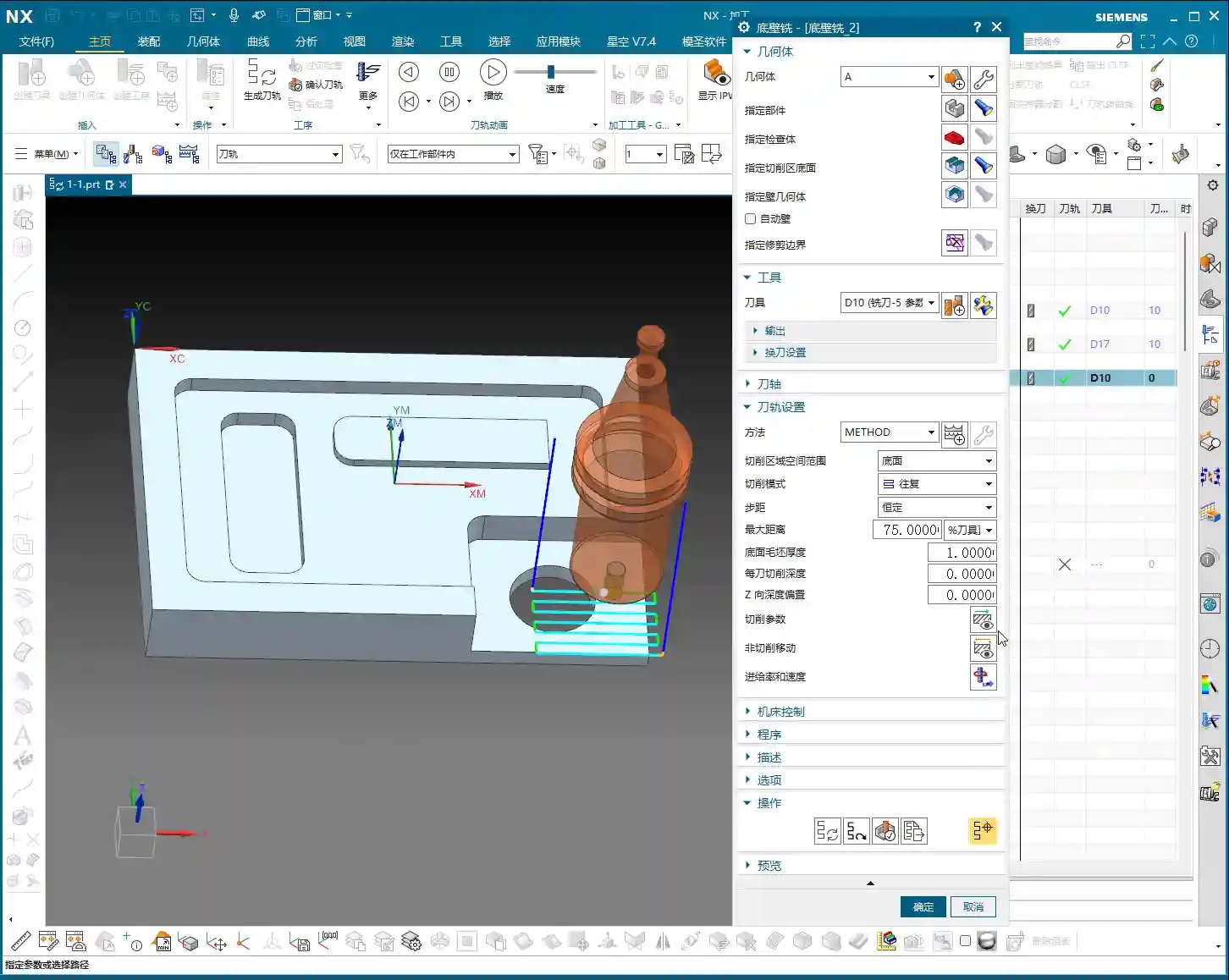
    So, we’ll skip these less frequently used parameters for now and focus on what’s truly important. Today, what we really need to talk about is the main event within “Non-Cutting Moves”: Rapid Transfer and Entry Point. How well these two parameters are set directly impacts your machine’s machining efficiency, and most importantlyβ€”whether you’ll have a tool crash or scratch the workpiece!

    Rapid Transfer: The Art of Safety Height

    Listen up, “Rapid Transfer” refers to how the tool quickly moves from one location to another when it’s not cutting. The most critical aspect here is setting the safety height. Set it too low, and you risk a collision; set it too high, and you’ll have long air cutting times, wasting valuable machining time!

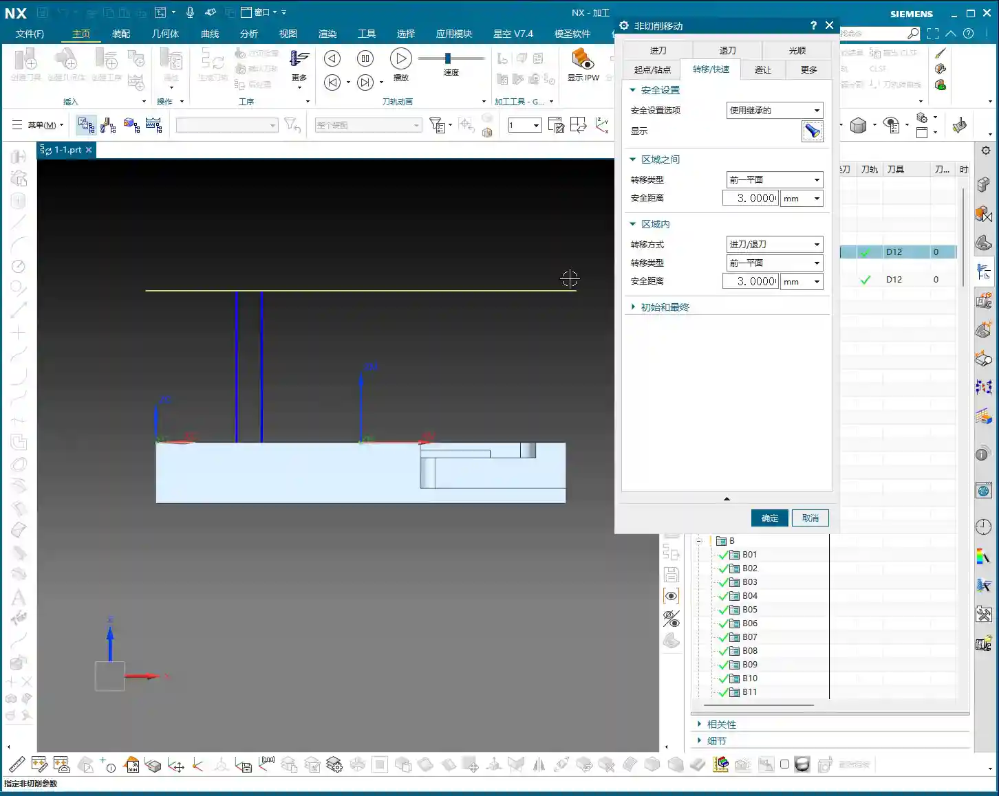
    Safety Plane: Default and Customization

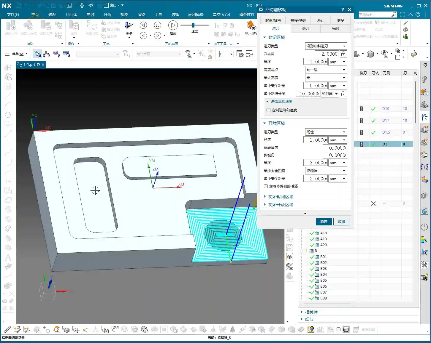
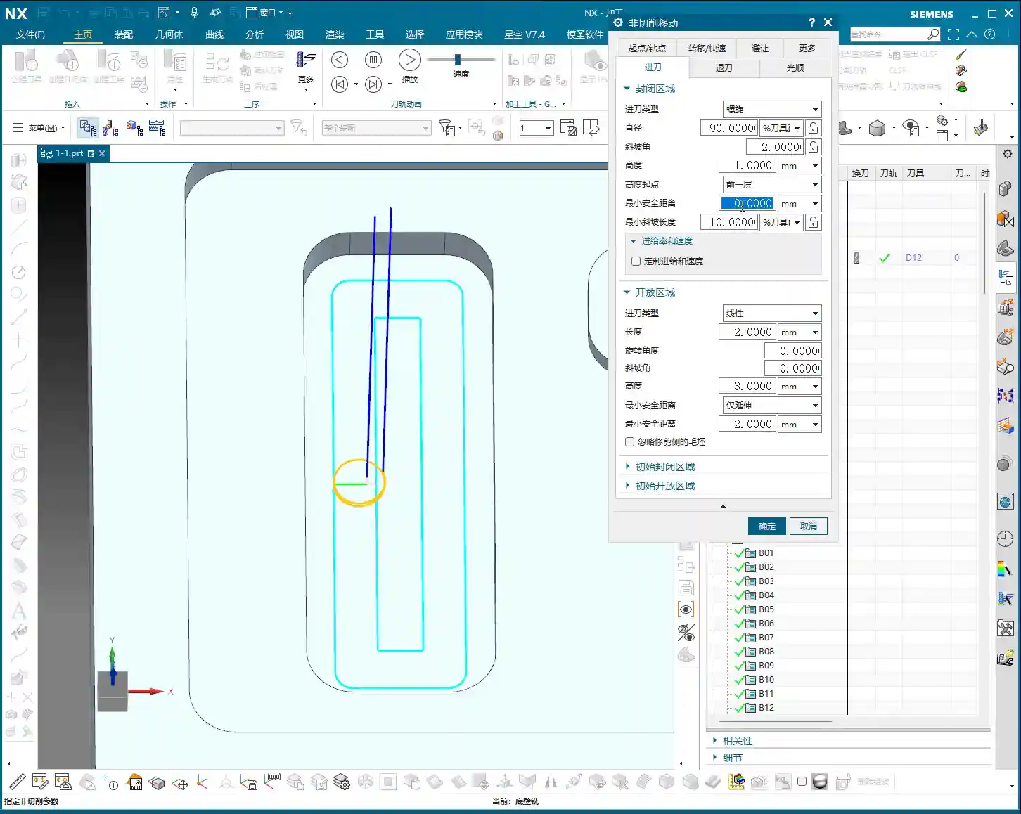
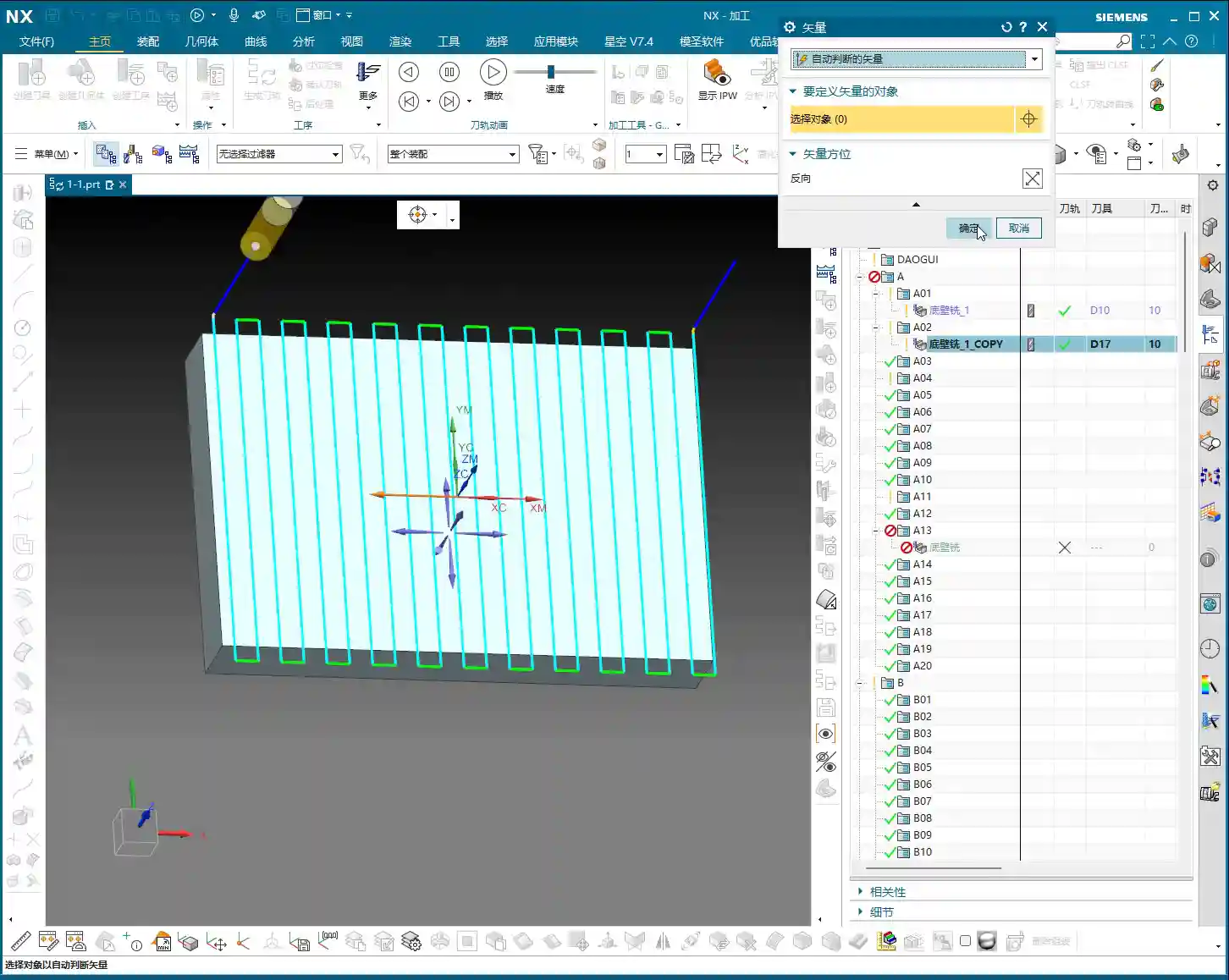
    In Siemens NX, it typically provides a default value that follows your initial setup. For example, when you create a new CAM setup and define geometry, don’t you usually set a Safety Plane, typically at Z100mm? The “Inherited” option within “Rapid Transfer” ensures the tool lifts to this height before moving. It’s the safest approach, but also the most conservative.

    • Inherited Mode: Most of the time, I recommend beginners stick with this. It refers to your initially set Safe Plane, for instance, Z100mm, and the tool will lift to this safety height for every non-cutting move. The advantage is safetyβ€”it’s less likely to crash. The drawback is that if the workpiece isn’t tall, or if machining regions are close, lifting this high every time will significantly increase Air Cutting Time, effectively wasting the machine’s valuable machining efficiency.
    • Plane Mode: You can choose this mode when you have an intimate understanding of the workpiece, fixturing, and tool paths. For example, if we’re machining a plate that’s only 20mm thick, lifting to 100mm every time is a huge waste. In such cases, you can lower the safety plane to 10mm or 20mm. But remember, this modification applies only to the current operation and won’t change global settings. After making changes, always meticulously check the tool path, especially ensuring the tool’s lift-off path doesn’t interfere with the fixturing or hit any protrusions on the workpiece. Don’t just rely on software simulation; pay attention to the cutting sparks and the machine’s actual operation! Safety first, efficiency second, but high efficiency is always pursued on the premise of ensuring safety.

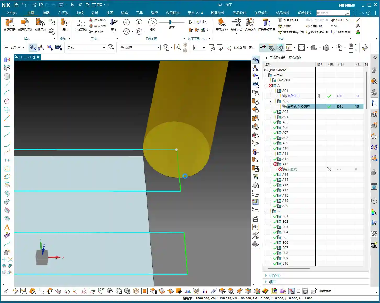
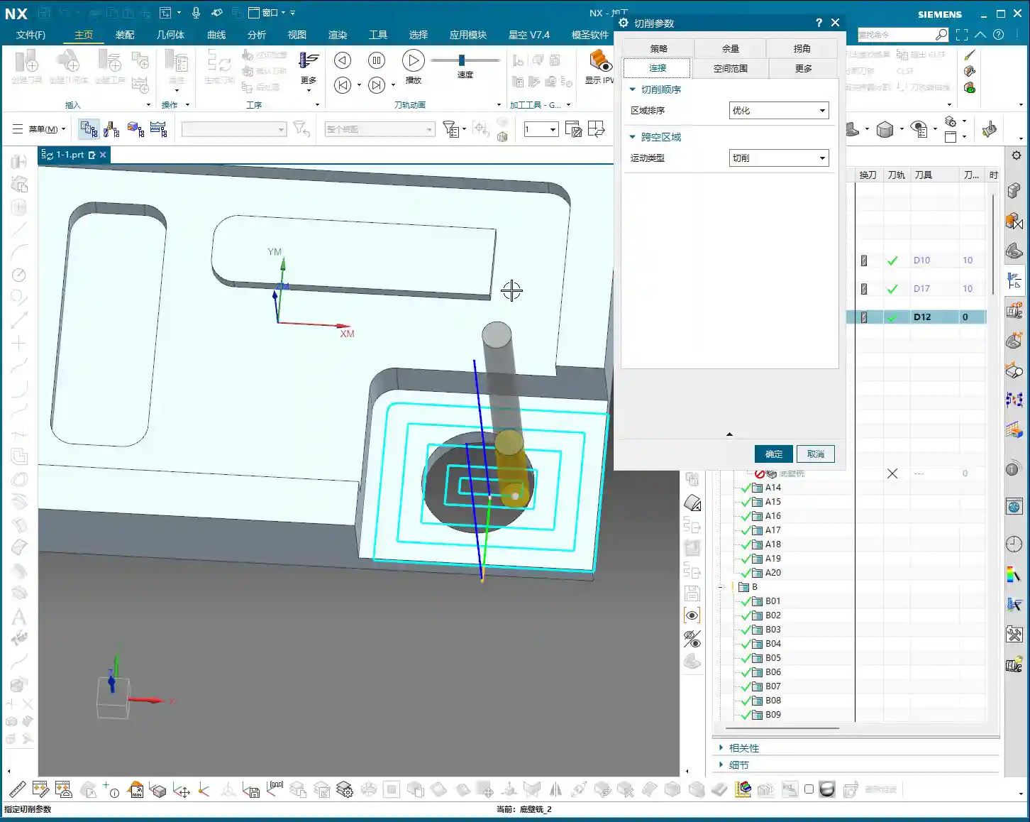
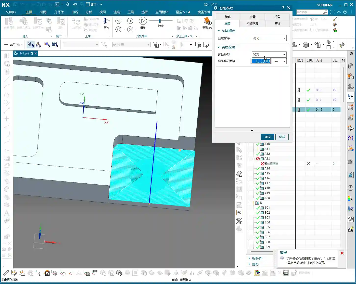
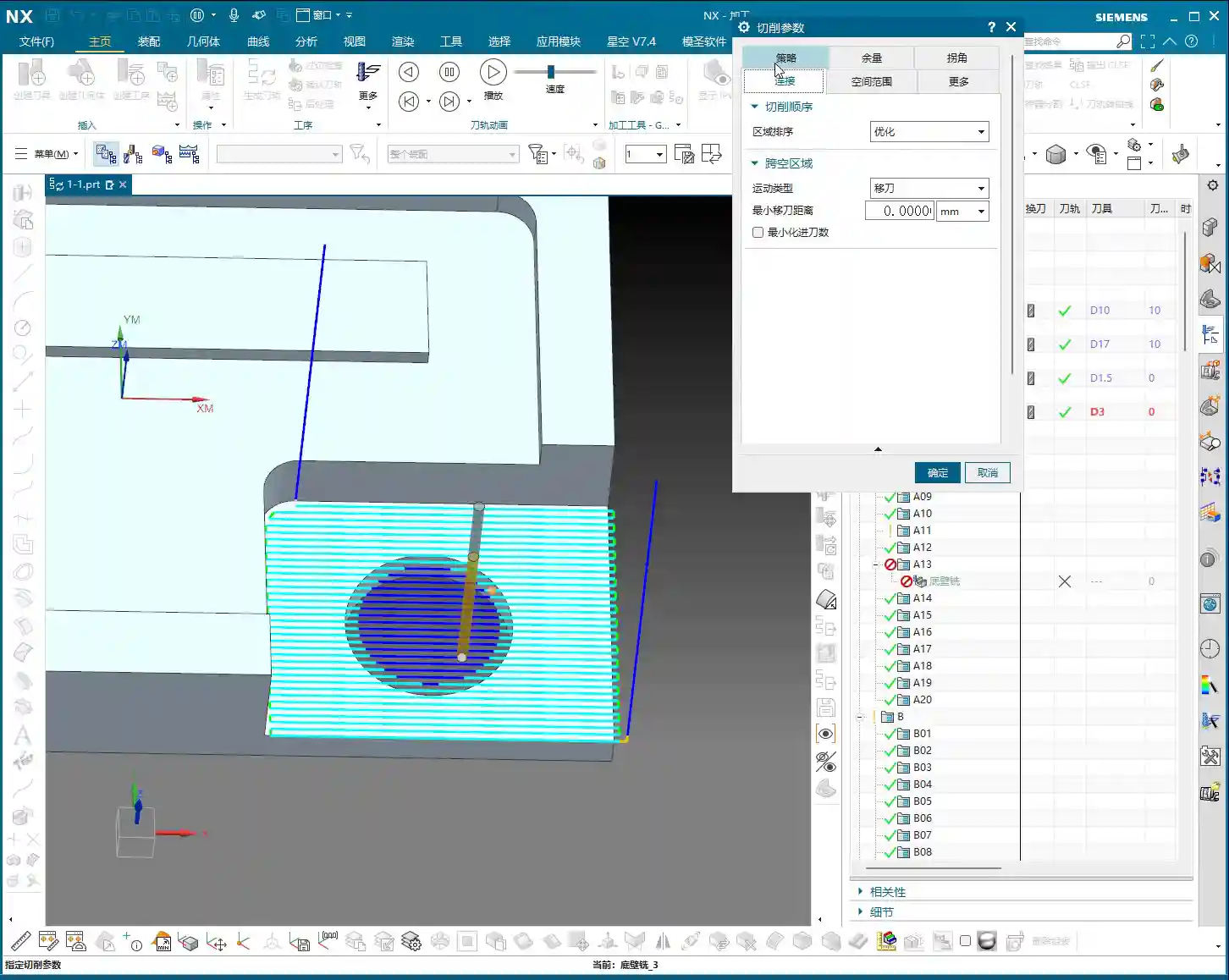
    Between Regions and Within Region: Meticulous Calculation

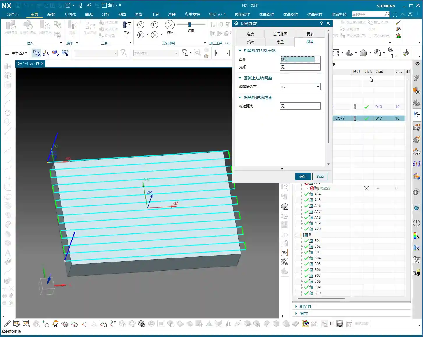
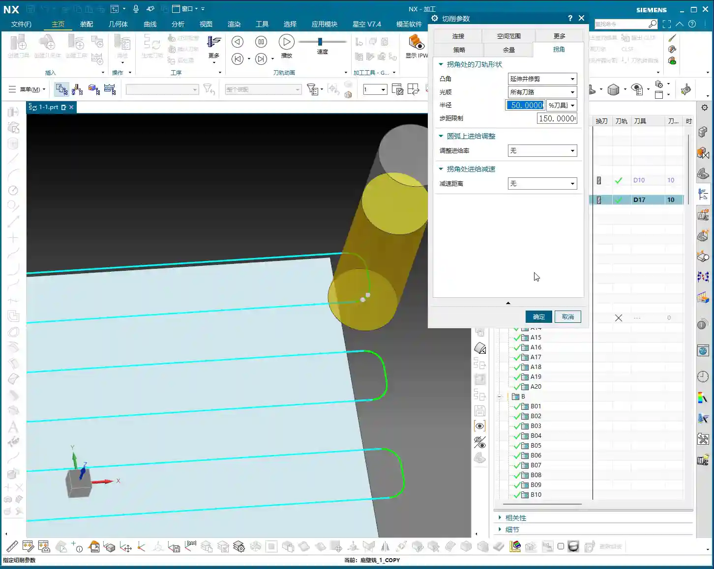
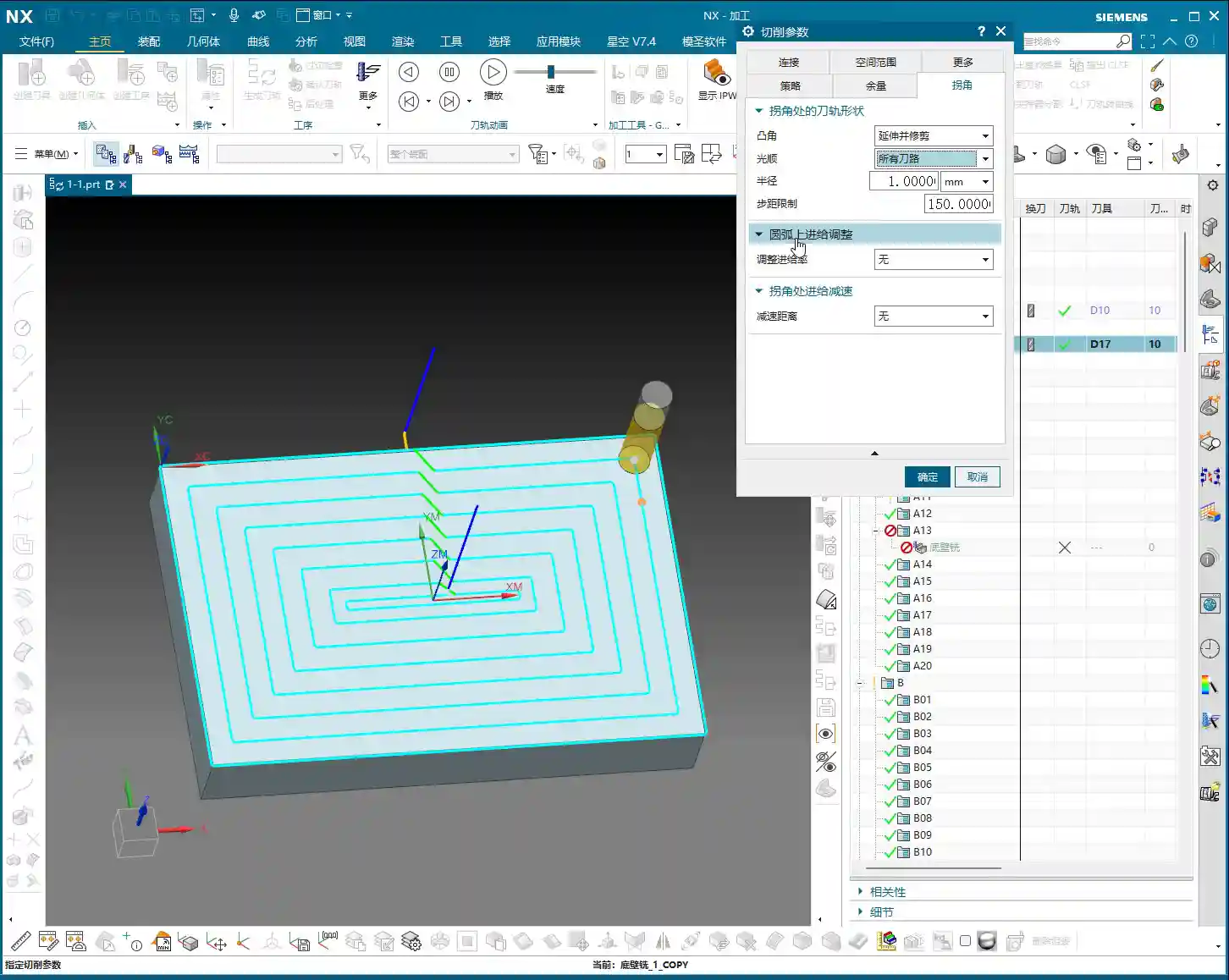
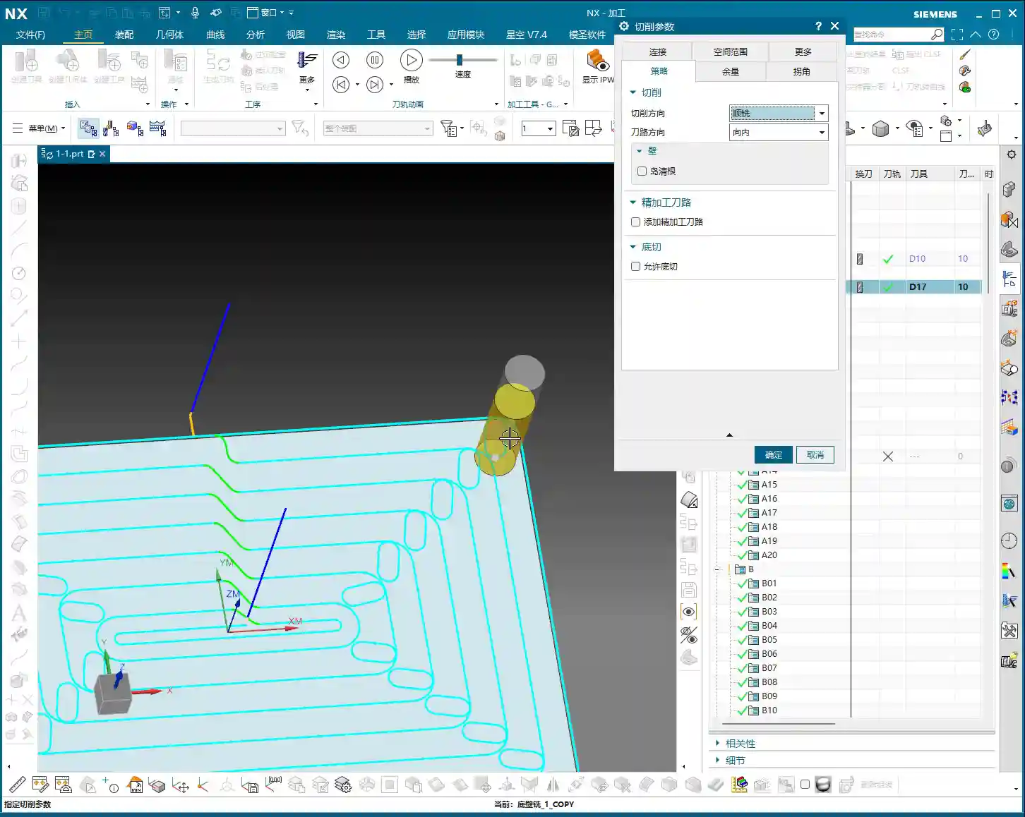
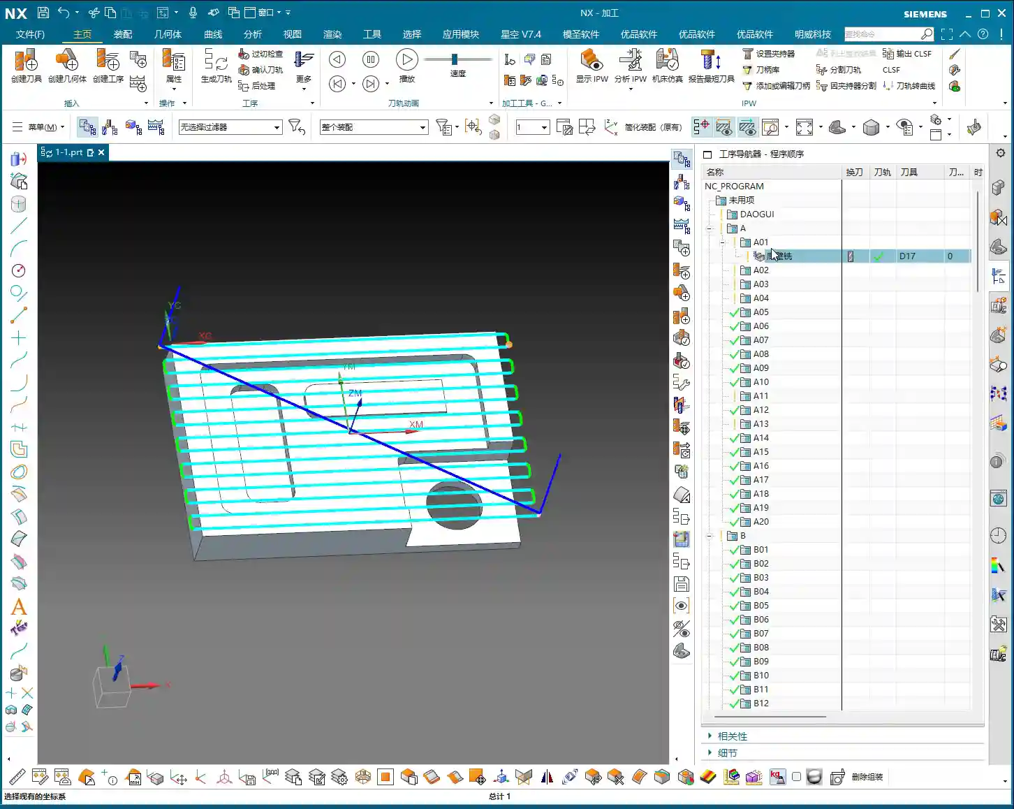
    This is where many beginners get confused. Siemens NX further subdivides “Non-Cutting Moves” into “Within Region” and “Between Regions.”

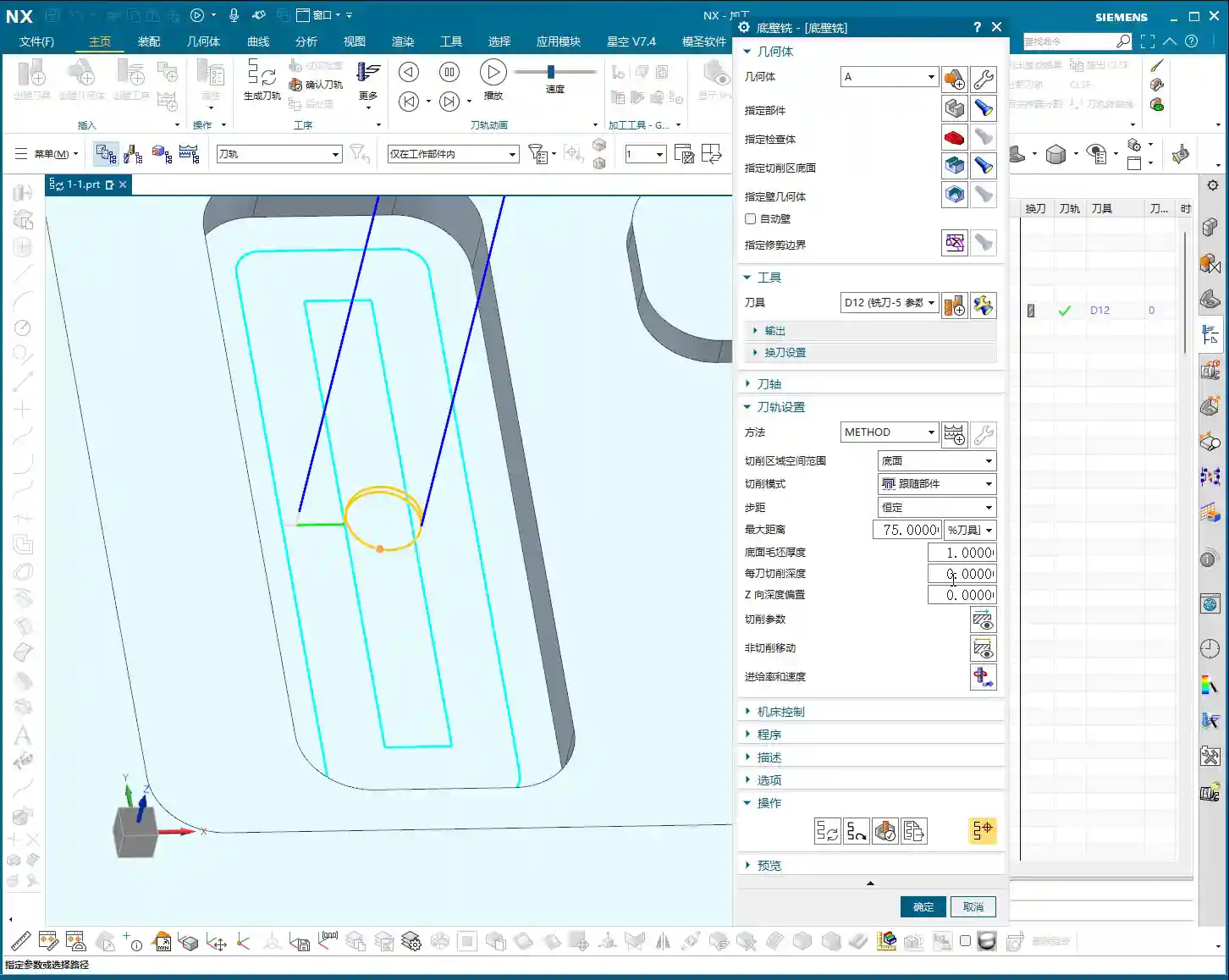
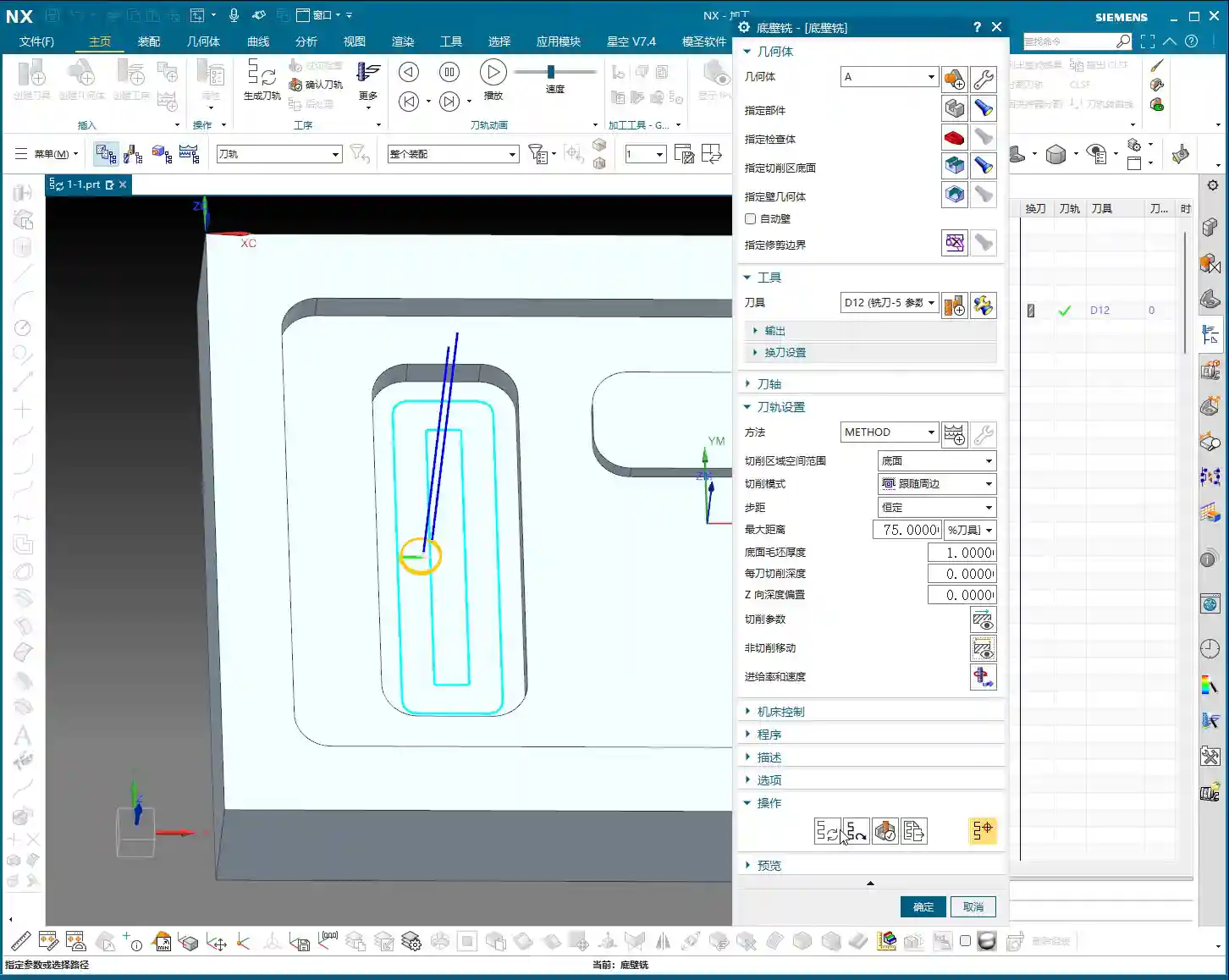
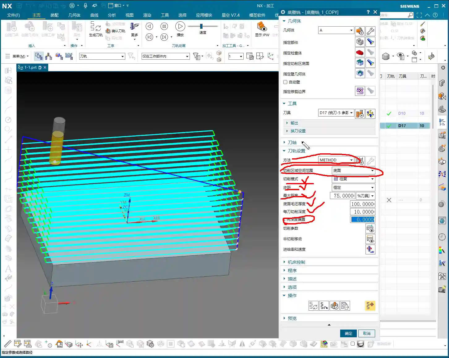
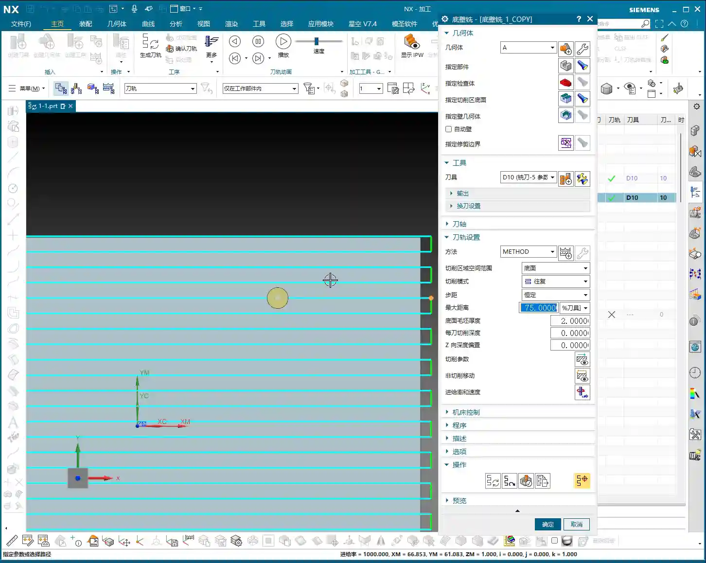
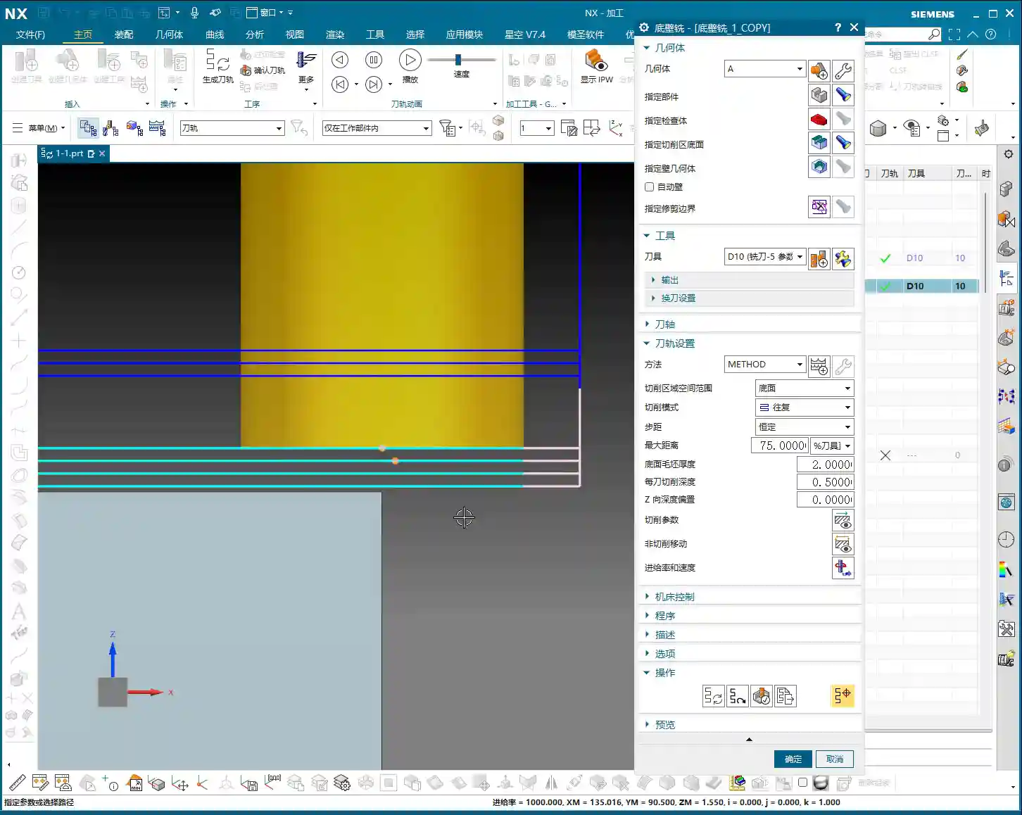
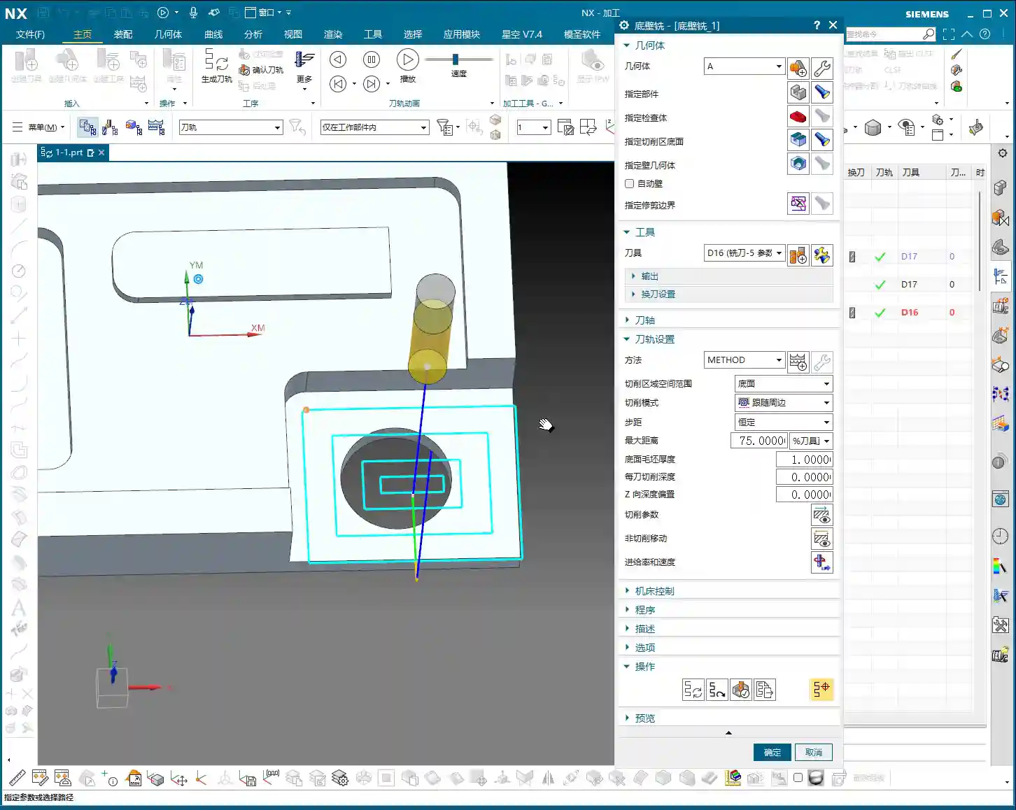
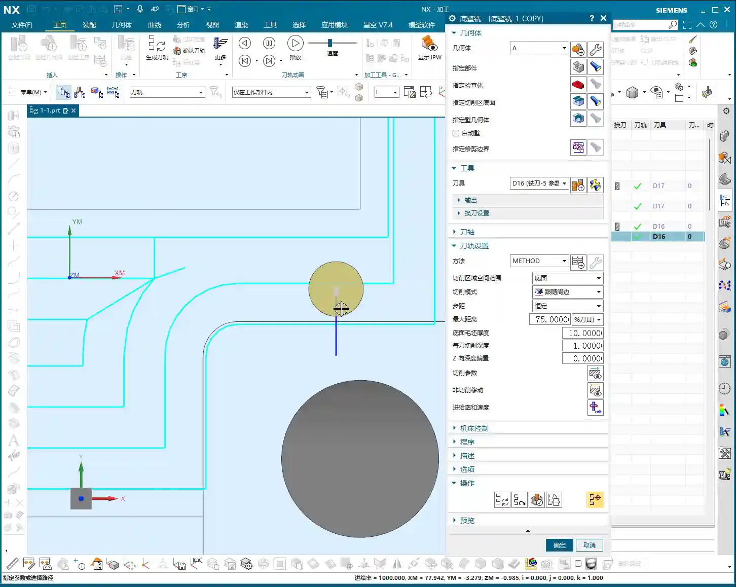
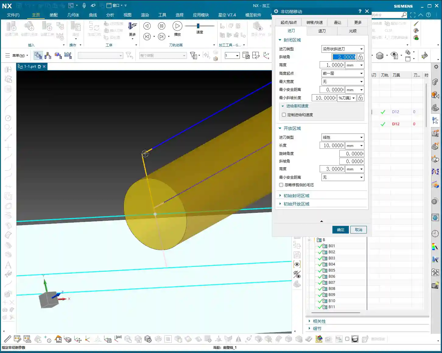
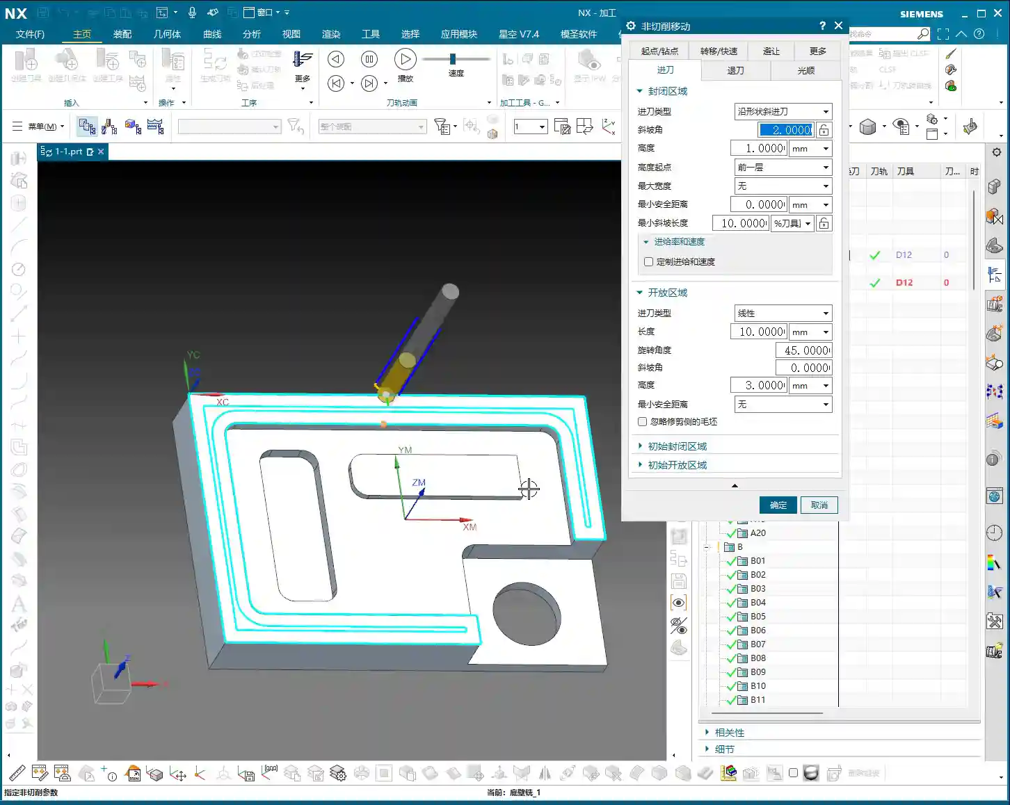
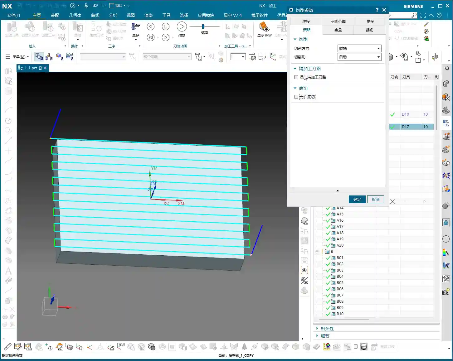
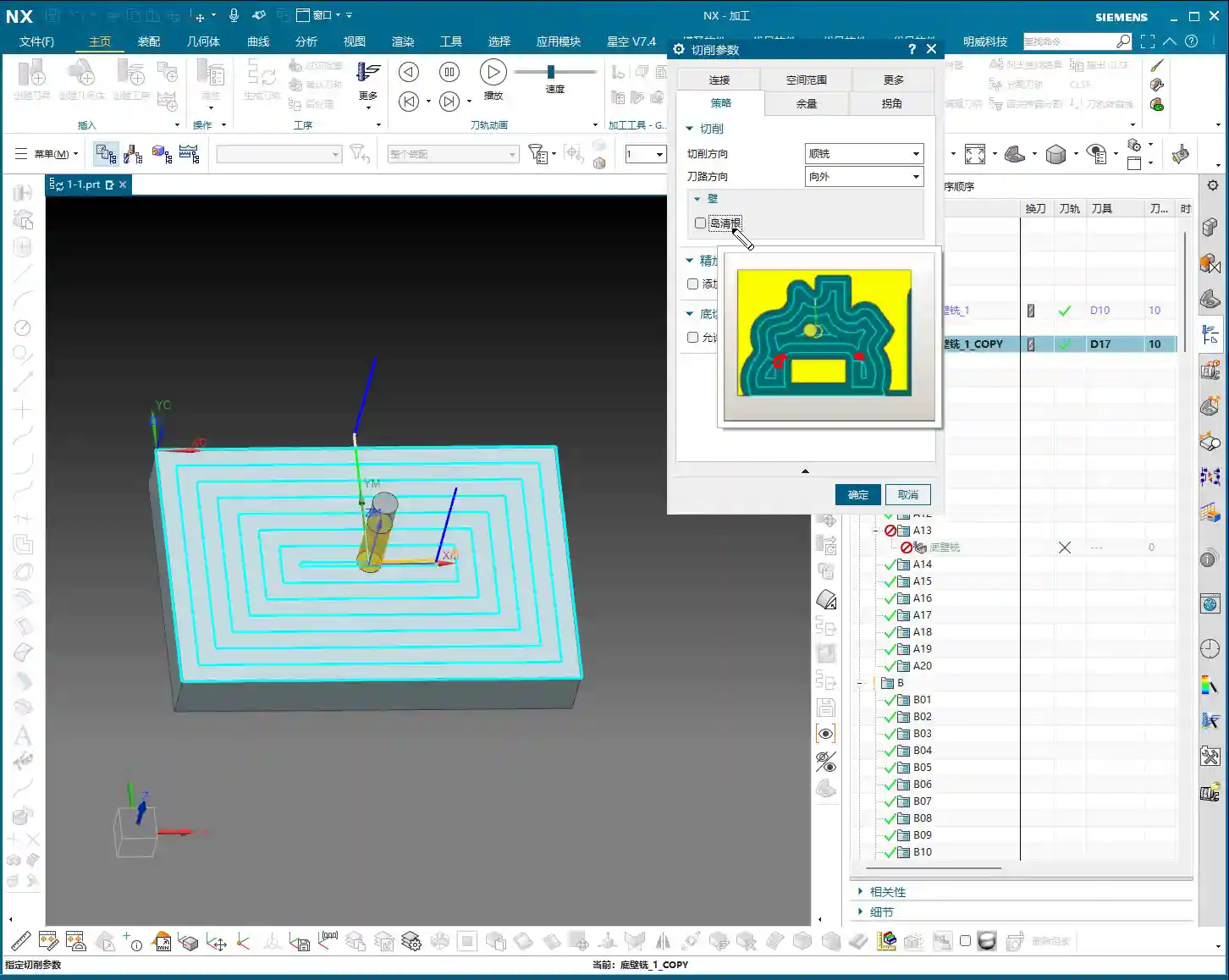
    • Within Region: Imagine you’re milling a large flat surface, and the tool moves between a series of small slots, all within the same larger machining region. In this scenario, the tool only needs to lift to a very small safety height, just enough to clear already machined areas or the workpiece itself. We typically set this height quite low, for example, 2mm or 5mm, ensuring it doesn’t scratch the machined surface while reaching the next cutting point as quickly as possible. This is often used for localized tool lifts in Smooth tool paths or Cavity Milling operations.
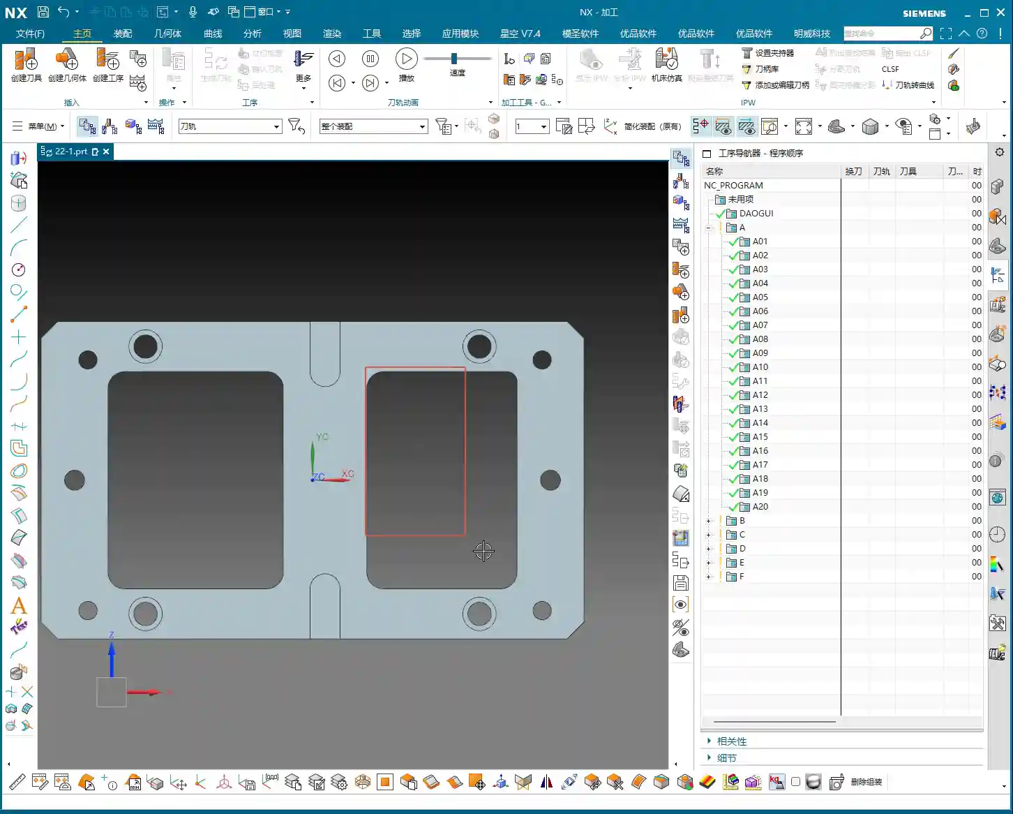
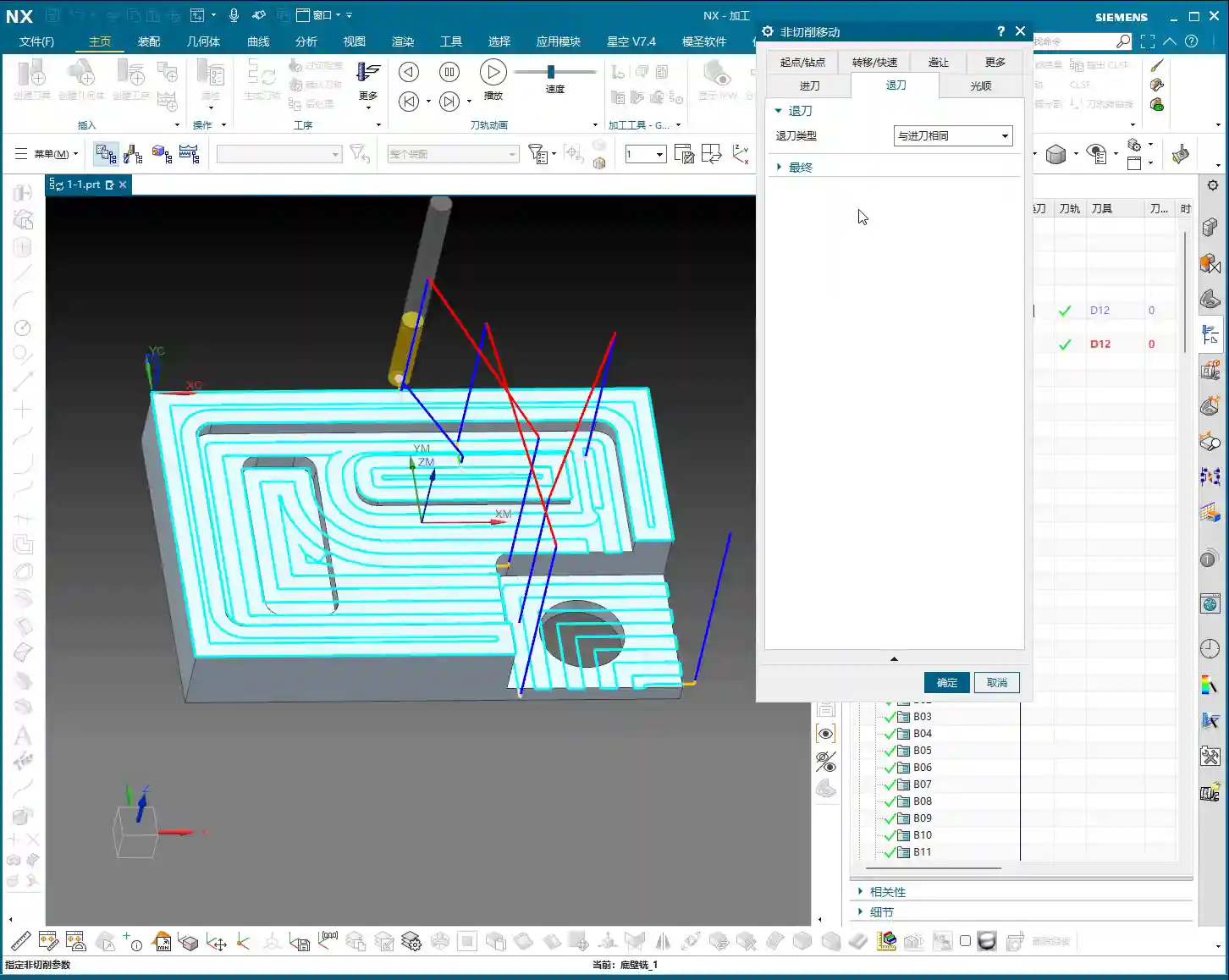
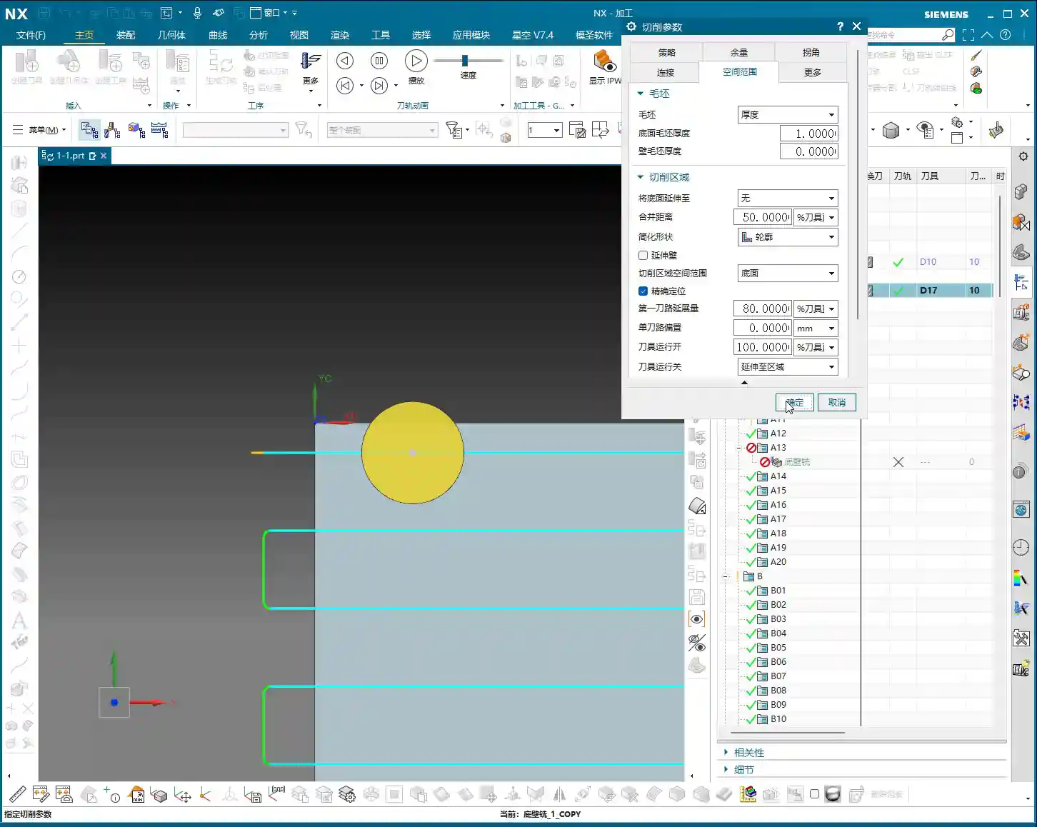
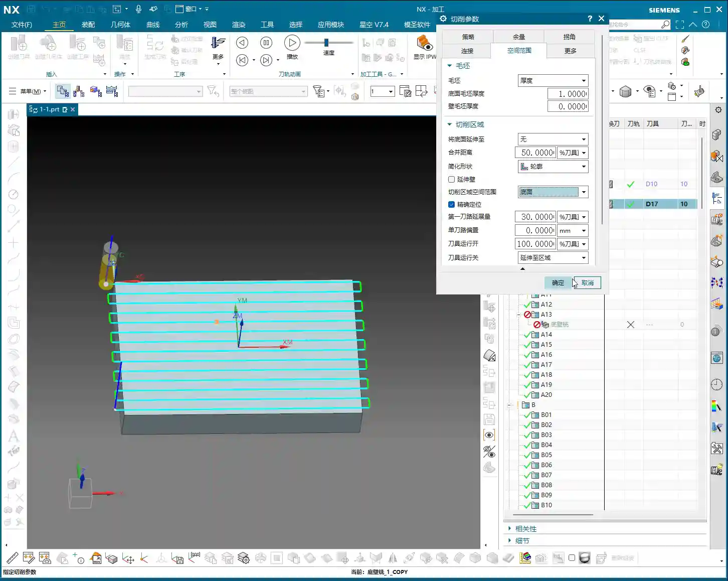
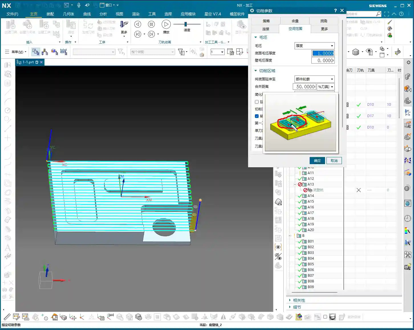
    • Between Regions: This is where it gets interesting. This refers to the tool needing to transfer from one independent machining region (e.g., a pocket) to another entirely unrelated region (e.g., another pocket, or a side wall). In this case, the tool needs to lift high enough to clear all potential obstacles, such as fixturing, unprocessed raw material edges, or other features on the workpiece. In the video, I demonstrated changing this value from the default 100 to 50 or even lower, and you can see the blue transfer path becoming noticeably shorterβ€”that’s how you save time! But the precondition is that you must ensure this 50mm height genuinely clears all obstacles. My experience tells me that initially, you can set it higher to guarantee safety. Once you’re proficient and fully understand the relative positions of the workpiece, tool, and fixturing, then you can gradually reduce it.

    So, you see, this “Rapid Transfer” is an art of balance. If the safety height is set correctly, your tool can avoid crashes and move swiftly, skyrocketing your machining efficiency. Conversely, you’re either sluggishly air cutting, or you accidentally hear a “bang,” ruining the workpiece, breaking the tool, and potentially damaging the machine. All that is money down the drain!

    Entry Point: Precise Positioning, Reduced Wear

    Next up is “Entry Point & Transition Point,” which is also quite important. How and where the tool enters the material directly affects tool life and machining quality.

    Engage Distance: Make the Tool Entry Smoother

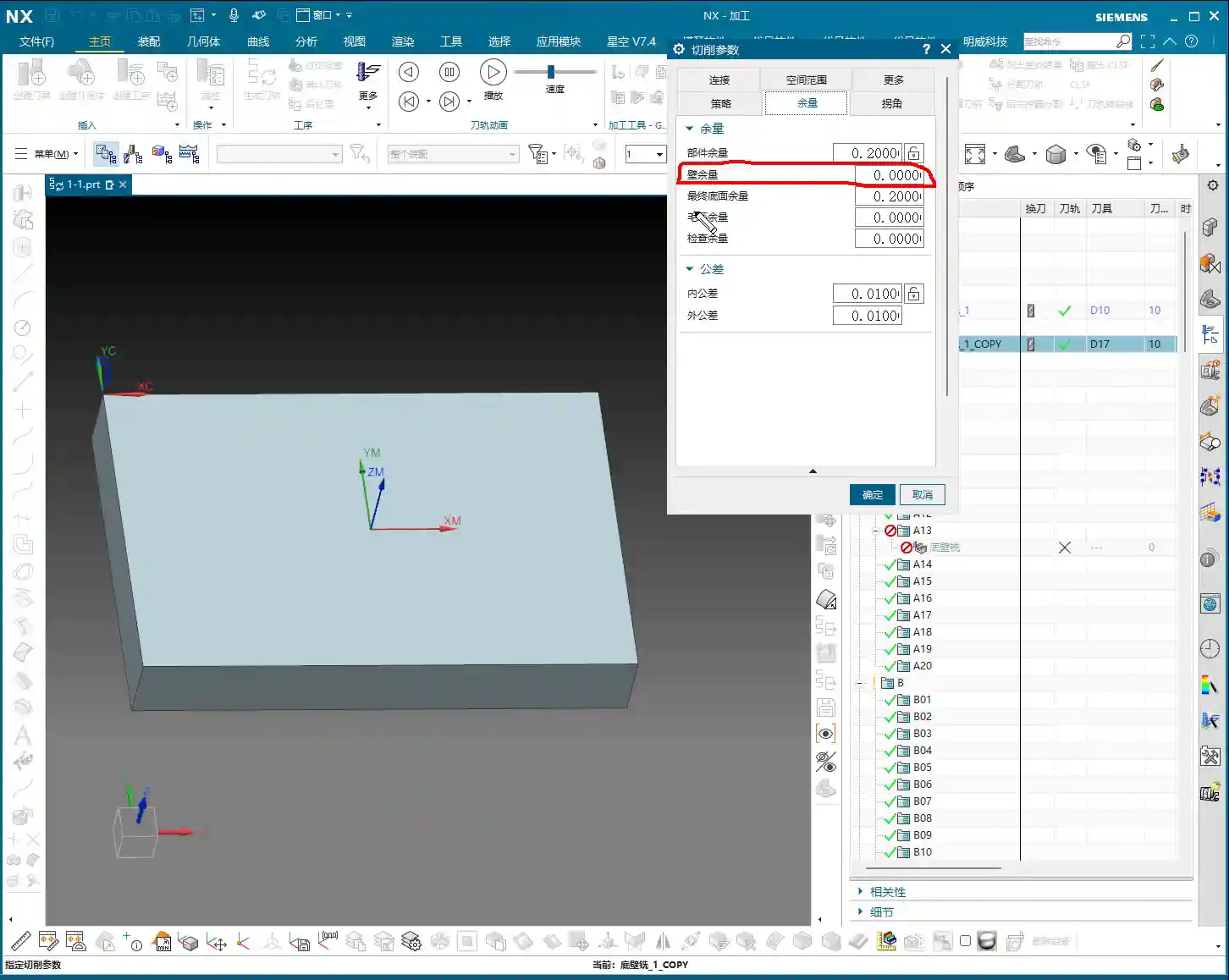
    The “Engage Distance” option, simply put, gives the tool a buffer before it truly starts cutting. For instance, when milling a side wall, if the tool plunges directly from the edge, the impact force will be considerable, often leading to chipping. In such cases, you can set an “Engage Distance”, allowing the tool to start its entry a small distance away from the side wall, then slowly feed into the cutting position. This makes the tool entry much smoother and “gentler.”

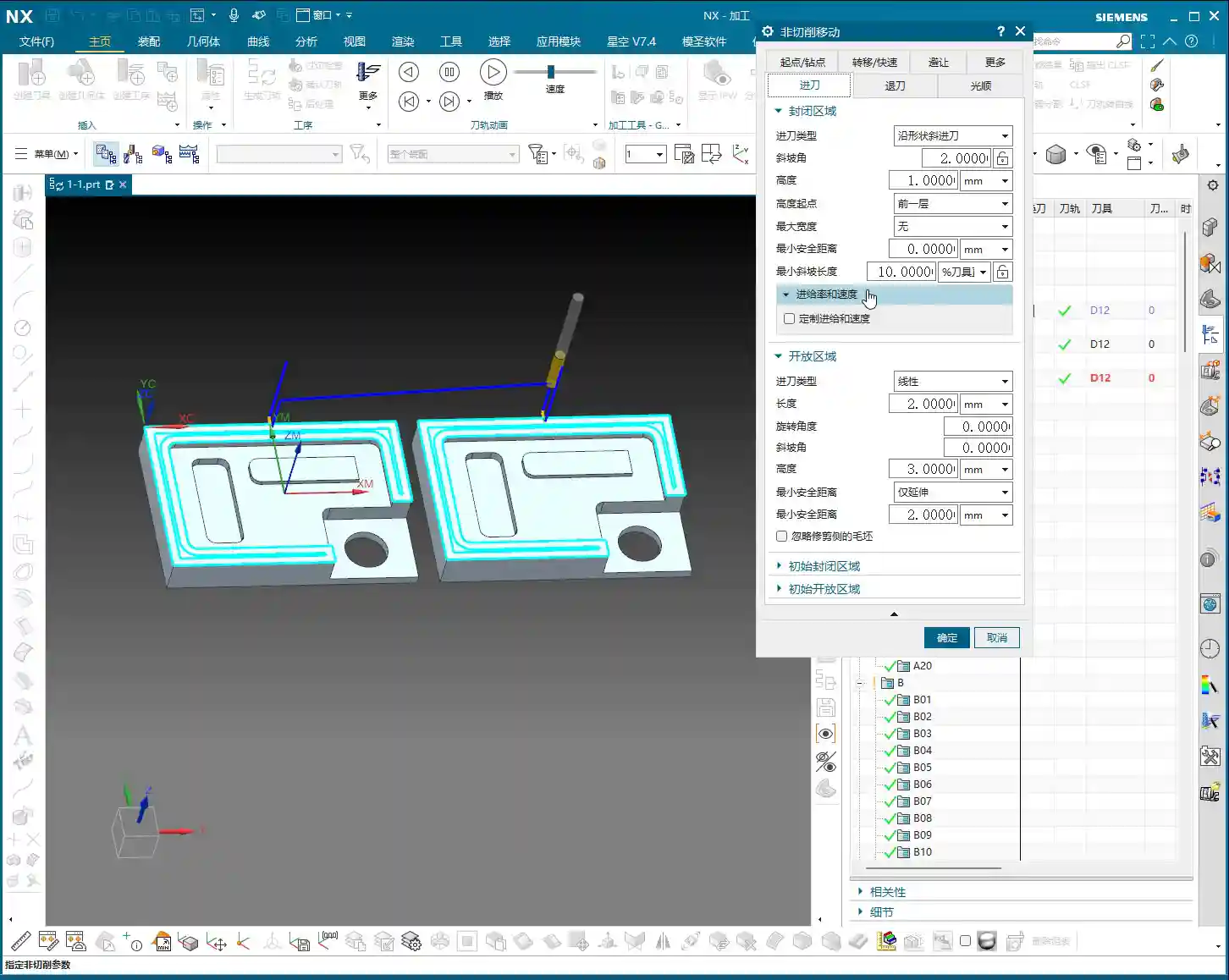
    The video mentions the case of “finishing a side wall,” where this distance becomes especially critical. For example, when we perform a finishing pass on a part’s side wall, requiring extremely high surface quality. If the tool plunges directly in, the cutting chatter will leave marks, affecting the surface finish. Setting an engage distance of, say, 3mm to 5mm allows for a smooth transition before cutting begins, which can significantly improve surface quality and extend tool life. This is all based on practical experience!

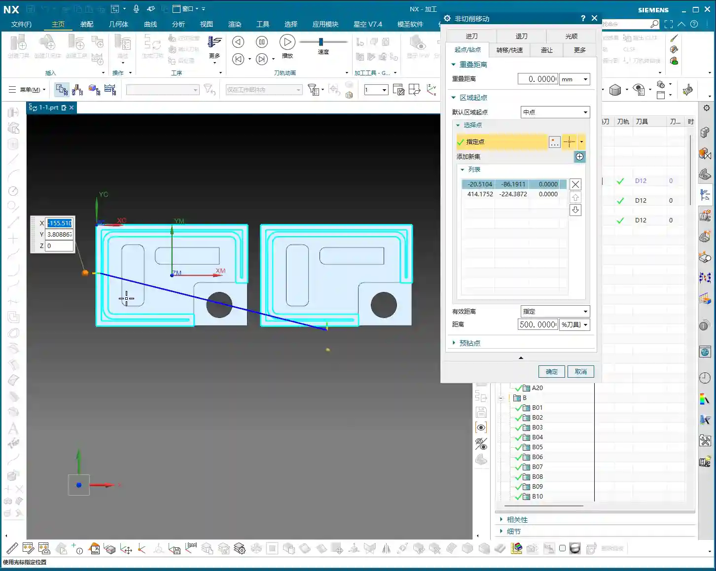
    Specify Point: Manual Intervention, Total Control

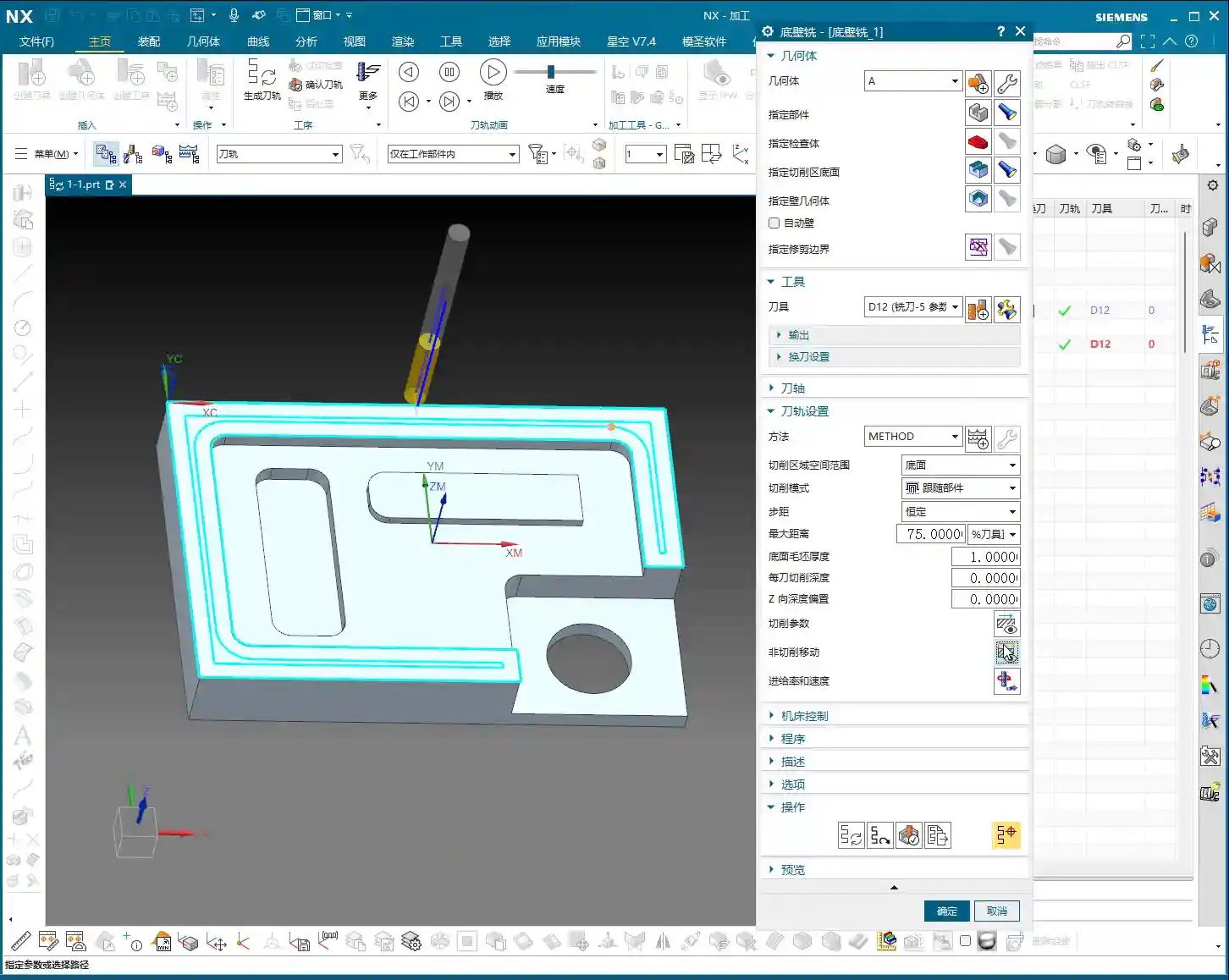
    By default, Siemens NX intelligently selects the entry point for you. However, many times we need to intervene manually because the software doesn’t know the height of your fixturing, which part of the workpiece is raw stock, or where pre-machined holes are located. The “Specify Point” function gives you precisely this control.

    • Avoid Obstacles: The most common use is to avoid fixturing or special features on the workpiece. For example, if you’re machining a part where the side is clamped by fixturing, or there’s an already finished surface nearby, you definitely wouldn’t want the tool to enter there. In such situations, you can manually select a safe and appropriate position as the entry point.
    • Optimize Cutting: Sometimes, entering the material from a specific angle or position is most favorable for tool force distribution, reducing tool wear and improving cutting stability. For instance, if cutting forces are mainly concentrated at the tool tip, tool life will be shorter. Entering from a relatively spacious area or where the material allowance is uniform can better distribute the cutting forces.
    • Multiple Entry Points: The video also mentions that you can specify multiple entry points in Siemens NX. For example, when machining a part with multiple internal pockets, each pocket requires an independent entry. You can then specify different entry points for different regions, ensuring each area starts cutting safely and efficiently. Remember, when selecting, the point you click will be highlighted, ensuring you’ve chosen the correct location.

    This isn’t something you can just click randomly. Choosing the wrong spot could lead to tool damage at best, or a collision with fixturing, even destroying the workpiece at worst. So, when specifying entry points, you must consider the raw material condition, fixturing location, and tool characteristics comprehensively. This is practical experience; it’s not something software simulation can fully replace.

    Summary: Pitfall Avoidance Guide

    Alright, that’s all for today’s valuable insights. Remember Master Wang’s advice:

    1. Rapid Transfer: Its core is the safety height. Beginners should first use “Inherited” to ensure no tool crashes. Once proficient, based on the actual workpiece and fixturing, boldly experiment with “Plane” mode to lower the transfer height “Between Regions” and reduce air cutting time. However, you must double-check repeatedly, especially by validating it extensively with simulation software, and then, once on the machine, slow down the feed rate and carefully observe the tool’s trajectory.
    2. Entry Point: “Engage Distance” is to ensure smoother tool entry, protect the tool, and enhance surface quality, especially for finishing passes. “Specify Point” is for avoiding obstacles, optimizing cutting, and extending tool life. When selecting points, you need to be precise and quick, have a clear understanding, and make judgments based on practical conditions.
    3. Non-Cutting Moves: It’s not just about moving the tool from one spot to another; it’s a comprehensive consideration of safety, efficiency, tool life, and surface quality. Simulate extensively in the software, observe keenly on the machine, and accumulate practical experienceβ€”only then can you truly become an excellent programming master.

    Don’t just stare at the computer screen watching tool path simulations; those are virtual. A true expert can correlate the virtual tool path with actual cutting sparks, chip formation, and machine chatter to judge whether the tool path is reasonable. This kind of expertise is gained by hands-on experience on the shop floor. Ponder over this well; it’s more valuable than reading ten books!

    Next time, I’ll chat with you all about something else.

    πŸ‘€ About the Author:
    The author is a veteran CNC machining professional with 15 years of industry experience, specializing in UG NX programming. This article is an original work representing personal practical insights.

    ⚠️ Copyright Notice: Unauthorized reproduction or distribution without prior communication is strictly prohibited.

  • Siemens NX CNC Machining: Practical Secrets for Entry Motion in Enclosed Regions and Helical Entry –

    πŸ“ Key Takeaways:

    Siemens NX Enclosed Region Entry Motion: Master Wang’s Practical Tips

    Hello everyone, I’m Old Wang, Master Wang. I’ve been working at the…

    Hello everyone, I’m Old Wang, Master Wang. I’ve been working at the machine shop for fifteen years, and I’ve seen it all: turning, milling, planing, grinding, EDM. With Siemens NX, it’s not just about building models; the real skill is programming toolpaths that are both fast and stable.

    Today, let’s talk about entry motion and enclosed regions in Siemens NX machining. Don’t think it’s just a few clicks in the software; there’s a lot more to it, and you won’t learn these tricks from textbooks.

    Non-Cutting Moves Overview: Why is Entry Motion So Important?

    Listen up: in Siemens NX, when programming toolpaths, besides the actual cutting process, a critical aspect is non-cutting moves. This includes entry motion, retract motion, smoothing, and so on. Don’t underestimate these rapid moves; they directly impact your machining efficiency and tool life. Incorrect entry motion can lead to minor tool wear, or worse, chipped tools, tool breakage, or even a machine crash!

    Entry motion, in particular, is the tool’s first contact with the workpiece, determining the initial state of cutting forces on the tool. Especially when encountering enclosed regions, the tool cannot simply enter from the side; it must “drill” into the material. This requires careful consideration of how to “drill” in a stable and efficient manner.

    Region Type Analysis: Enclosed vs. Open, How Siemens NX Sees It?

    First, you need to understand whether the area you’re machining is enclosed or open. Siemens NX programming is much smarter than you might think.

    What is an Enclosed Region?

    Simply put, it’s an area where the tool cannot directly enter from the side. For example, a fully enclosed deep pocket, blind hole, internal groove, etc. The tool must either plunge vertically into the material or descend to the specified depth via helical or ramp entry before cutting can begin.

    Master Wang’s Insight: When encountering such areas, the tool is like a diver entering the water; it needs a safe and stable way to descend. Otherwise, plunging straight in will lead to severe Depth of Cut (DOC), causing problems!

    What is an Open Region?

    As the name suggests, this is an area where the tool can freely enter from the outside of the workpiece or from the side of an already machined area. For example, the outer contour of a part, an open slot, or an internal area that has already been opened up through roughing.

    Master Wang’s Insight: Open regions are much easier; the tool can directly plunge in, or gently “graze” in from the side, eliminating the need for helical entry and resulting in higher efficiency.

    Siemens NX’s Intelligent Judgment: Don’t Blindly Change Parameters!

    I want to emphasize that Siemens NX is very intelligent! After you select a machining region, it will automatically determine whether it’s an enclosed or open region. Accordingly, it will only apply the entry motion parameters you’ve set for that specific region type.

    • If you’re machining an enclosed region, then changing “open region entry motion parameters” as much as you like will be useless! It will only look at the settings under “enclosed region entry motion.”
    • The inverse is true: when machining an open region, it will only acknowledge the “open region entry motion” parameters.

    Master Wang’s Reminder: Don’t waste time changing parameters that won’t take effect! You might think the software will obey you, but in reality, it has its own “judgment.” You need to clearly identify what type of region you’ve selected, then apply the appropriate settings. The yellow line in the software simulation is the entry path you really need to pay attention to!

    Entry Strategies for Enclosed Regions: Helical is King!

    For enclosed regions, the most common and safest entry method is Helical Entry. The tool slowly descends in a helical path, gradually engaging the material, which avoids the massive impact of vertical plunging and significantly extends tool life.

    Helical Entry Core Parameters

    In Siemens NX’s “Non-Cutting Moves” settings, find “Enclosed Region Entry Motion,” and pay close attention to these parameters:

    • Diameter: This parameter controls the diameter of the helical entry. It’s usually defaulted to 90% of the tool diameter.

      Master Wang’s Insight: Don’t arbitrarily reduce this value! If the diameter is too small, the tool’s center load becomes excessive, leading to wear and even tool breakage. Especially when machining hard materials like titanium alloys or high-temperature nickel-based alloys, ensuring sufficient diameter is crucial for tool survival.

    • Ramp Angle: This is the angle at which the tool descends helically. It’s usually defaulted to 2 degrees.

      Master Wang’s Insight: This angle is the balance point between efficiency and safety. A smaller angle means smoother entry, less force on the tool, but a longer entry time. A larger angle means faster entry, but also greater impact and load on the tool.

      • Soft materials (e.g., aluminum): The angle can be appropriately increased, for example, to 3-5 degrees, to improve efficiency.
      • Hard materials (e.g., mold steel, titanium alloys): Be conservative, maintain 1-2 degrees, or even smaller, to ensure tool safety.
      • Tool characteristics: Two-flute tools can tolerate larger entry angles than multi-flute tools because the cutting force is distributed among fewer flutes.

    • Start Height for Ramp: This parameter determines the Z-axis height from which the helical entry begins. In Siemens NX, options like “Incremental Depth,” “Current Length,” or “Top Surface” are common.

      Master Wang’s Insight: Generally, choosing “Incremental Depth” (or a similar setting relative to the previous cut) is safer, meaning the tool starts its helical path from the bottom of the previous toolpath or a safe height above it. You can also specify an absolute value, such as 1mm or 2mm (approx. 0.04-0.08 inch), allowing the tool to begin helical entry 1-2mm above the current cutting plane.

      Practical Point: This height should not be set too high, as it will result in too many rapid moves and waste time. Nor should it be set too low, as the tool might crash into the material before even starting the helical path.

    Minimum Safe Distance

    This parameter, during helical entry, controls the minimum distance between the helical path and the workpiece wall. When you set this value, for instance, 0.1mm (approx. 0.004 inch), the tool’s outermost edge will maintain at least 0.1mm clearance from the workpiece wall during helical descent.

    Master Wang’s Insight: This is about giving the tool “breathing room”! Especially with new tools, high-precision machining, or when slight machine wear causes accuracy deviations, setting a small safe distance can effectively prevent the tool from scraping the sidewall during helical entry, protecting the tool and ensuring the side wall’s surface finish. However, this value shouldn’t be too large, or it will leave stepped unmachined material, requiring subsequent cleanup, which creates more hassle. Typically, 0.05-0.1mm (approx. 0.002-0.004 inch) is sufficient.

    Minimum Ramp Length

    This is an easily overlooked, yet critically important parameter for certain tools! It refers to the minimum cutting width that needs to be maintained during helical entry to ensure that the tool’s effective cutting edges are fully engaged.

    Master Wang’s Secret: Tool Type and Ramp Length Percentage

    • Solid Carbide End Mill: These tools typically offer full-flute cutting, with no “blind spot” at the tool tip. Therefore, their helical entry diameter can be relatively small, such as 10% to 20% of the tool diameter, or even smaller.

    • Indexable Insert Tool: Pay attention! Tools like face mills and shell mills are assembled with inserts, and their centers often have a “blind spot” – an area without cutting edges. If your helical entry path diameter is too small, causing the tool’s central blind spot to contact the workpiece, you’re asking for trouble – increased tool wear, unstable cutting, poor surface finish, or even immediate tool breakage!

      For indexable insert tools, the helical diameter corresponding to this “Minimum Ramp Length” parameter typically needs to be set larger. Generally, it’s recommended to set it to 50% to 70% of the tool diameter to ensure all inserts effectively engage in cutting and avoid the blind spot. Remember, don’t just rely on software simulation; consider the actual tool geometry and cutting principles!

    Summary: Pitfall Avoidance Guide

    1. Clarify Region Type: Before machining, always clearly determine whether it’s an enclosed or open region to avoid setting ineffective parameters. Siemens NX will make its own judgment, but you should have a clear understanding as well.
    2. Fine-Tune Helical Entry Parameters:

      • Diameter: Generally keep the default 90%, unless you have special considerations, such as a small diameter tool machining a deep hole.
      • Ramp Angle: Adjust according to material hardness and tool type. Use a small angle for hard materials, and a slightly larger angle for soft materials. But always remember: safety first!
      • Start Height for Ramp: Select an appropriate Z-value to avoid excessive rapid moves and prevent collisions.

    3. Balancing “Minimum Safe Distance”: Don’t set it too large, or it will leave unmachined material; don’t set it too small, or there’s a risk of scraping. 0.05-0.1mm (approx. 0.002-0.004 inch) is the common range.
    4. “Minimum Ramp Length” is Key: For indexable insert tools, this is paramount! Ensure the helical diameter is large enough to prevent the tool’s blind spot from cutting into the workpiece. This is based on experience, not something the software can fully account for on its own.
    5. Optimization Means Savings: Every parameter adjustment directly impacts your machining time, tool consumption, and product quality. Don’t be afraid to experiment; adjust, simulate multiple times, and find the optimal process parameters for your needs.

    Alright, that’s all for today. Remember, software is just a tool. A true expert understands these parameters, making the machine work for them, instead of being led by the software!

    πŸ‘€ About the Author:
    The author is a veteran CNC machining professional with 15 years of industry experience, specializing in UG NX programming. This article is an original work representing personal practical insights.

    ⚠️ Copyright Notice: Unauthorized reproduction or distribution without prior communication is strictly prohibited.

  • Siemens NX Cornering Strategies: Master Wang’s In-Depth Guide to Preventing Residual Material, Impro

    πŸ“ Key Takeaways:

    NX Machining: Practical Corner Handling

    Hello everyone, I’m Master Wang. Today, we’re skipping the theoretical fluff and getting straight…

    Hello everyone, I’m Master Wang. Today, we’re skipping the theoretical fluff and getting straight to the hardcore stuffβ€”in NX, this **corner handling** is a huge topic and often where problems arise. Don’t be fooled by a few checkboxes in the software; there’s a lot more to it, directly impacting your part’s accuracy, surface quality, and your hard-earned machining efficiency!

    I. Extend and Trim

    Listen up, “Extend and Trim” is a pretty common option in NX. What does it mean? Just look at this small icon, and you’ll get it.

    Principle Explained

    When our tool reaches an external corner of a contour, for example, a right angle, how does it move? It doesn’t just foolishly stop at that point and abruptly turn; that would lead to the tool being overloaded and chatter. NX will let the tool’s center point **extend slightly beyond**, which is what we call “extend”, and then come back to “trim” off the excess. The goal is to ensure the tool fully cuts into the corner, machining that sharp angle completely.

    Practical Tips

    • This option is mainly used for **external sharp corners**. It ensures that the defined contour boundary is machined cleanly and completely, without leaving any rounded corners.
    • When using it, pay special attention to **tool radius compensation**. If compensation is incorrect, the tool extending too little or too much can lead to overcutting or undercutting.
    • I generally use this when machining parts that require strictly maintained sharp external contours, such as square frames or right-angle steps. Remember, this is to ensure **geometrical accuracy**.

    II. Roll Over

    “Roll Over” is quite interesting. The difference from “Extend and Trim” becomes clear if you carefully observe the software simulation.

    Principle Explained

    “Roll Over” means that when the tool reaches a corner, whether external or internal, it will **automatically transition with an arc**. The tool doesn’t just go in a straight line to the sharp point but rather “rolls” over, using a fillet to complete the turn. This is like driving around a bend; no one drives straight into a corner and then makes a sudden 90-degree turn – that would surely result in a crash!

    Practical Tips

    • This option is used relatively little in actual machining because its behavior can be somewhat “random”, especially at **sharp corners, where it might generate an unnecessary arc**. If it creates a small arc where there should be a right angle, isn’t that just ruining the part?
    • My personal experience is that if the drawing requires sharp corners, **use this option with caution**; it can easily round off intended sharp corners, especially internal corners, leading to a risk of **residual material** or **overcutting**.
    • Unless you specifically require the tool to transition with an arc at all corners, I recommend using other options first, or carefully inspecting the toolpath.

    III. Smooth

    This “Smooth” function is really useful! Its purpose is to soften the toolpath at corners, avoiding sudden stops and abrupt turns, which benefits both the part’s surface finish and the machine’s lifespan.

    Principle Explained

    The core of the “Smooth” function is to **insert an arc transition at corners**. When the tool follows the contour to a corner, it generates a small arc there instead of making a sharp 90-degree turn. This arc transition effectively prevents impacts and vibrations caused by sudden changes in the tool’s cutting direction.

    Setting the Smooth Radius

    The most crucial setting here is the **Smooth Radius**. It determines the size of the corner arc.

    • Percentage (%): The default is usually 5%. This percentage is relative to your current **tool diameter**. For example, if you use a D10 (10mm diameter) end mill and set it to 5%, it will generate an arc with a radius of 0.5mm at the corner. If you change it to 50%, that would be R5.
    • Millimeters (mm): You can also directly input a fixed radius value, such as 1mm or 2mm. This is more straightforward; no matter what size tool you use, it will apply the fixed radius you set for the arc transition.

    Differences in Internal and External Corner Handling

    • Internal Corners: When the tool enters an internal corner (e.g., an internal corner of a square pocket), if “Smooth” is selected, it will generate an arc with the set radius for the transition. The advantage of this is that it **effectively reduces residual material in internal corners**, preventing the tool from “pausing” or being “overloaded” in the corner, allowing for smoother cutting, and avoiding tool chipping or part chatter marks. I typically set the smooth radius for internal corners between 0.2mm and 1.0mm, depending on part requirements and tool size.
    • External Corners: Interestingly, for external corners, such as a 90-degree angle on an external contour, even if you set “Smooth”, it will usually **still follow a sharp angle**. This is because the tool follows the contour, and by going directly through the external corner, it already achieves the “sharp corner” effect. However, if you apply a large smooth radius, such as R5 or even R10, it can still be used to **optimize toolpath smoothness**, and although it doesn’t significantly affect the final part geometry, it can make the machine run more smoothly, reduce impact, and extend machine life.

    Step Limit and Residual Material Cleanup

    When discussing “Smooth”, the concept of “Step Limit” often comes up. Although it was a bit vague in the audio, essentially, it is closely related to **clearing residual material in corners**.

    • You need to understand that if internal corners are not handled properly, the tool cannot completely remove the material in those corners, leaving **residual material**. It might look clean in the software simulation, but on the actual machine, there might be a lump of material waiting for you.
    • The “Step Limit” parameter, if set correctly (e.g., 100% or even 150%), can assist the “Smooth” function by giving the tool enough “room” to clear residual material in internal corners. It forces the tool to take an extra short pass in these corners, ensuring no material remains.
    • Generally, using the default value of 150% is fine and can effectively prevent residual material in internal corners. However, in special cases, such as deep cavities, you might need to increase this value for thorough cleanup.

    IV. Feed Rate Adjustment on Arc and Corner Slowdown

    Feed Rate Adjustment on Arc

    • This option is used relatively infrequently. It means that you can independently adjust the feed rate when the tool is following an arc path.
    • In actual machining, most of the time we rely on the machine’s **G61/G64 (Exact Stop/Continuous Machining)** commands or the automatically optimized feed rates from the CAM software, and rarely manually fine-tune arc feed rates. Unless there are special requirements, I generally leave it untouched.

    Corner Slowdown

    • This one, however, can be useful. As the name suggests, when the tool reaches a corner, it automatically reduces the feed rate.
    • It is typically set as a **percentage**, for example, setting it to 50% means that at the corner, the feed rate will be reduced to 50% of the currently set feed rate.
    • **Why slow down?** To reduce impact between the tool and workpiece, lower vibration, prevent premature tool wear, and improve machining quality, especially when machining hard materials or requiring a high surface finish.
    • **My advice**: If you’re machining hard materials, or if the tool is prone to chipping, you might consider reducing the speed. However, generally, CAM software and the machine’s control system already do a good job, so I rarely explicitly set this parameter myself. After all, slowing down means **increased machining time and reduced efficiency**, so you need to weigh the pros and cons.

    Summary: Guide to Avoiding Pitfalls

    1. Extend and Trim: Ensures sharp external contours are fully machined, preventing undercutting. Check toolpath for overcutting. Commonly used for external contour machining requiring precise sharp corners.
    2. Roll Over: Use with caution! It might generate arcs where they are not intended, leading to non-conforming parts or residual material. Avoid it unless specifically required.
    3. Smooth: This is a powerful tool for optimizing toolpaths and improving surface quality.

      • Internal Corners: Essential! Effectively clears residual material, reduces tool impact, and improves surface finish. The radius value should be flexibly adjusted based on tool and part accuracy requirements; 0.2mm-1.0mm is commonly used.
      • External Corners: Primarily used to improve machine motion smoothness; has little impact on part geometry. A larger radius can be applied.
      • Step Limit: The default value of 150% is usually sufficient, working with “Smooth” to clear residual material in internal corners. If residual material remains, it can be increased.

    4. Corner Slowdown: Consider using for hard materials or high-precision requirements, but weigh it against efficiency. Unless necessary, the default is usually fine, or leave it to machine control.
    5. Core Principle: **Don’t just rely on software simulations; watch the cutting sparks!** The actual machining result is the only true test. Observe the machine’s running status, listen to the sounds, monitor cutting conditions, and flexibly adjust parameters based on experience – that’s the real key to success!

    πŸ‘€ About the Author:
    The author is a veteran CNC machining professional with 15 years of industry experience, specializing in UG NX programming. This article is an original work representing personal practical insights.

    ⚠️ Copyright Notice: Unauthorized reproduction or distribution without prior communication is strictly prohibited.

  • Siemens NX Toolpath Colors, Stepover, and Depth of Cut (DOC): Master Wang’s Practical Machining Tips

    πŸ“ Key Takeaways: Master Wang personally shares core insights on NX toolpath colors, stepover, and Depth of Cut (DOC). From air cuts to actual material removal, this guide deeply analyzes the practical significance of each step, teaching you how to precisely adjust parameters based on material and tooling, avoid common pitfalls, and significantly improve machining efficiency and part accuracy.

    Hello everyone, this is Master Wang. Today, let’s pick up from our last discussion and talk about the secrets of “reading tool intent by color” in NX programming, along with the critical parameters of stepover and Depth of Cut (DOC). These are hardcore insights that directly impact your efficiency and scrap rate, so listen up!

    I. Toolpath Colors: NX Tells You What the Tool is Doing

    In NX software, toolpath colors aren’t just for show; they indicate the tool’s actions, corresponding to different G-code movements on the machine. You must understand these colors to truly grasp the tool’s intent. Software simulation alone isn’t enough; you need to combine it with observing actual cutting sparks!

    1. Blue: Rapid Moves – Go Fast!

    See this blue toolpath? This represents Rapid Traverse, which corresponds to the machine’s G00 command. The tool moves at its fastest speed above the workpiece or in areas where it’s not in contact. This is an “air cut,” not removing material. So, in these areas, we aim for maximum speed – get there fast, don’t waste time!

    Master Wang’s Tip: During rapid moves, always ensure the tool won’t collide with the workpiece or fixturing. Leave ample clearance; otherwise, a crash means the machine, tool, and workpiece are all scrapped!

    2. Yellow: Approach – Stay Steady!

    When the tool slowly approaches the workpiece from the air, preparing to start cutting, you’ll see a yellow toolpath. This is called the Approach/Entry, marking the start of tool-workpiece contact. The corresponding G-code is G01, but the feed rate will be relatively slow to ensure smooth engagement and prevent tool impact. Helical and ramp entries are common strategies to avoid sudden material engagement, reducing tool wear and workpiece vibration.

    Master Wang’s Tip: The approach method and feed rate are crucial! Especially for deep cavities or hard materials, a poorly managed approach can lead to chipping or, worse, tool breakage. Slower and steadier is always better than rework. You can also set the approach to enter directly from outside the workpiece, which can reduce air cutting.

    3. Light Blue: Actual Cut – Watch the Sparks!

    The actual cutting begins! This is the light blue toolpath, representing Cutting, and it’s the core G01 action. At this point, the tool is genuinely removing material according to your programmed feed rate and spindle speed. What we often call “taking a bite” or “engaging the material” in the shop refers to this stage. This is the essence of your machining operation.

    Master Wang’s Tip: Don’t just rely on software simulation; watch the cutting sparks! The color, shape of the sparks, and the cutting sound can all tell you about the tool’s condition. If the sparks are too yellow and coarse, the feed rate might be too slow, or the tool is dull. If they’re too bright and fine, the feed rate might be too fast, leading to excessive tool load. You need to observe carefully; that’s experience you won’t learn from books.

    4. Green: Traverse Within Cut – Stay Engaged!

    Within the same cutting level, when the tool moves from one area to another to continue cutting, but without lifting (or only lifting slightly, still remaining within the Depth of Cut (DOC)), you’ll see a green toolpath. This is called Traverse within cut. Like the light blue toolpath, it’s a cutting action, merely a lateral movement of the tool on or within the workpiece surface. Essentially, it’s also engaged in cutting.

    Master Wang’s Tip: You can think of green and light blue as “brothers,” both actively working. Sometimes the software might even display them uniformly. The key is that the tool is still in a cutting state, or rather, it’s on its way to the next cutting point and hasn’t completely disengaged from the workpiece.

    5. Pink: Retract – Safety First!

    Once the job is done, the tool needs to leave. The pink toolpath that appears then is the Retract/Exit. The tool safely withdraws from the finished surface of the workpiece. Retraction also requires smoothness, especially during finishing passes, to avoid scratching the workpiece surface as the tool exits.

    Master Wang’s Tip: Retraction might seem simple, but don’t get complacent. Pay attention, especially during retraction, as some materials tend to generate burrs. Ensuring the tool safely withdraws from the workpiece is fundamental.

    II. Stepover: How the Tool Takes Its ‘Steps’

    Stepover is the distance between adjacent toolpaths when the tool moves laterally. This parameter determines your machining efficiency and surface quality. In NX, it’s typically referred to as “lateral stepover” or “sideways stepover.”

    1. Percentage Stepover: Intelligently Adapts to the Tool

    Listen up, the most commonly used and highly recommended option is percentage of tool diameter. For example, if you set it to 75%, this means the tool’s lateral movement distance each time will be 75% of the current tool diameter.

    Master Wang’s Tip: Why use percentages? Because tools change! If you switch to a larger tool, the stepover automatically increases; with a smaller tool, it decreases accordingly. This saves you from recalculating and re-entering stepover values every time you change a tool, making it convenient and less prone to errors. For roughing operations like Face Milling, I often set the percentage to 85% or even 90% for efficiency, as long as the machine and tool can handle it – it’s a solid approach. However, for finish cuts requiring high surface finish, you might need to reduce it to 50% or even less, allowing the tool to make more passes for a smoother surface.

    2. Absolute Stepover: For Specific Scenarios Only

    Besides percentages, there’s Constant, which means setting a fixed stepover value, such as 8 mm (approx. 0.315 inch). With this method, if the tool diameter changes, the stepover remains the same unless you manually adjust it. This is suitable for situations with extremely strict stepover requirements or simple machining with fixed tool types. We generally don’t use it often.

    Master Wang’s Tip: If you insist on using a fixed value, pay close attention. If you have a 10 mm (approx. 0.394 inch) tool and set an 8 mm (approx. 0.315 inch) stepover, that’s fine. But if you switch to a 5 mm (approx. 0.197 inch) tool and the stepover remains 8 mm, the tool will only cut a small portion, with the rest being air cuts, resulting in low efficiency. In some cases, a large stepover with a small tool can even lead to missed cuts or extremely poor surface quality. So, unless you have specific reasons, a percentage-based stepover is generally more reliable.

    III. Depth of Cut (DOC) Per Pass: How Deep to Cut – A Vast Subject

    The Depth of Cut (DOC) per pass is the distance the tool penetrates into the workpiece along the Z-axis each time. This parameter directly determines the cutting forces, tool life, machining time, and surface roughness. This is where your true craftsmanship is put to the test.

    1. Stock Allowance at Bottom and Multi-Pass Cutting

    In NX, there’s a parameter called “Stock Allowance at Bottom”, which refers to the total amount of material you need to remove from the bottom of the workpiece. For example, if your raw stock has 2 mm (approx. 0.079 inch) of allowance, then this parameter would be 2 mm.

    As for “Depth of Cut (DOC) per pass”, as the name suggests, it’s how deep you intend to cut with each pass. For instance, if the stock allowance is 2 mm (approx. 0.079 inch), and the Depth of Cut (DOC) per pass is 0.5 mm (approx. 0.02 inch), the tool will complete the 2 mm allowance in four passes.

    Master Wang’s Tip: Multi-pass cutting is common sense! Especially for roughing and hard materials, you can’t expect the tool to take a huge bite in one go. How much to remove each time must be determined by a comprehensive assessment of material hardness, tool diameter, machine power, and spindle rigidity. For difficult-to-machine materials like titanium alloys and high-temperature nickel-based alloys, the Depth of Cut (DOC) per pass must be very cautious; it’s better to make more passes than to overload the tool. For common aluminum, you can afford a slightly larger DOC.

    2. The Risk of Setting Depth of Cut (DOC) Per Pass to 0

    Listen up, here’s a major pitfall! If you accidentally set the “Depth of Cut (DOC) per pass” to 0, even if the “Stock Allowance at Bottom” is 2 mm (approx. 0.079 inch), the tool will “pretend” to make only one cut, going straight from top to bottom. This is practically a suicide mission!

    Master Wang’s Tip: Setting it to 0 means the program assumes you only need one pass to complete all cutting; it will attempt to remove all material at once. Do you think that’s possible? Unless the allowance is extremely small, or you have a super-powerful tool and machine. In general, this will lead to a series of severe consequences such as tool overload, tool breakage, machine collision, and scrapped workpieces. So, remember, you absolutely cannot easily set this parameter to 0! Unless you clearly know what you’re doing, and the allowance truly is 0, which typically only occurs during the final finishing pass.

    3. Adjustment Strategies in Practice

    In actual operation, the adjustment of Depth of Cut (DOC) per pass is flexible:

    • Roughing: You can appropriately increase the Depth of Cut (DOC) per pass to prioritize efficiency. However, ensure that the cutting forces remain within the machine and tool’s capacity.
    • Finishing: Typically, the Depth of Cut (DOC) per pass is reduced, sometimes even set to a very small value (e.g., 0.1 mm (approx. 0.004 inch) or less), to achieve better surface finish and dimensional accuracy.
    • Material Characteristics: For difficult-to-machine materials like stainless steel and titanium alloys, the Depth of Cut (DOC) must be significantly smaller than for common steels or aluminum. High-temperature nickel-based alloys require even greater caution, as tool burnout is a common occurrence otherwise.
    • Machine Power and Rigidity: For older or low-power machines, the Depth of Cut (DOC) cannot be too large; otherwise, it easily leads to chatter, affecting accuracy and surface quality. Only high-rigidity, high-power 5-axis machines can take deeper and faster cuts.

    Summary: Pitfall Avoidance Guide

    1. Understand toolpath colors: Blue is rapid move – go fast; yellow is approach – be steady; light blue is actual cut – watch the sparks; green is traverse within cut – stay engaged; pink is retract – ensure safety. These colors correspond to different G-codes and machine states, forming the first step in accumulating experience.
    2. Stepover: Percentage is preferred: In most cases, using a percentage of tool diameter for stepover automatically adapts to tool changes, avoiding manual calculations and errors. For Face Milling roughing, it can be larger; for finishing, it should be smaller.
    3. Depth of Cut (DOC) per pass must NEVER be set to 0: Unless it’s a finishing pass with extremely minimal allowance, setting it to 0 means the tool will attempt to remove all material at once, highly likely leading to tool breakage and machine accidents.
    4. Adjust parameters based on practical conditions: The parameters in NX are fundamental, but how you ultimately adjust them depends on the material you’re machining, the tools you’re using, the machine’s performance, and the part’s accuracy and surface finish requirements. Observe and reflect frequently – that’s the way to mastery.

    πŸ‘€ About the Author:
    The author is a veteran CNC machining professional with 15 years of industry experience, specializing in UG NX programming. This article is an original work representing personal practical insights.

    ⚠️ Copyright Notice: Unauthorized reproduction or distribution without prior communication is strictly prohibited.

  • UG NX 1980 Plane Milling Operations: From Roughing to Corner Cleanup, Master Machinist’s Hands-On Pr

    πŸ“ Key Takeaways: Join Master Wang as he dives deep into UG NX 1980 plane milling operations. From the overall concept to specific applications like roughing, corner cleanup, helical milling, and engraving, he’ll guide you through setting up coordinate systems, creating geometry, and highlighting common pitfalls to boost machining efficiency and precision.

    Hello everyone, I’m Master Wang.

    Listen up. Starting today, we’re going to dive deep into plane milling. This isn’t just a simple job; there are many subtleties involved, and it can be broken down into many sub-processes.

    Plane Milling: A Big Family

    See, I’ll open up the operation interface for you. We’ve already covered Floor and Wall Milling and its capabilities, so I won’t repeat those details. Today, we’re focusing on plane milling.

    Although it’s all called plane milling, it’s actually a general term, like the ‘boss’ of the family. Under this boss, there are many ‘branches,’ each capable of handling specific tasks. There are quite a few branches, so let me list some common ones for you:

    1. Roughing

    The first one is Roughing. Normally, for roughing, we use a face mill (or sometimes a side-cutting end mill, but the side flute can also cut). This operation feels similar to dynamic milling. It can not only machine flats (face milling) but also side walls, and you can even use the side flutes for corner cleanup. It’s highly efficient.

    2. Plane Profile Milling

    Plane milling also branches out into something called Plane Profile Milling. In fact, it’s also part of the plane milling family, but it’s specifically used for tasks such as:

    • Roughing side walls
    • Finishing side walls
    • Adding chamfers

    See, it can do quite a lot!

    3. Contour Chamfering

    Then there’s Contour Chamfering. You could also say that plane milling can perform chamfering because this operation is derived from plane milling. These two terms are essentially linked together.

    4. Helical Milling

    Helical Milling is also a type of plane milling. In specific deep pocket or hole machining, helical entry can effectively avoid center cutting, reduce tool wear, and improve machining stability.

    5. Engraving

    You heard that right, plane milling can even be used for engraving! While this function isn’t commonly used, it can be extremely useful in critical situations. There’s also 2D Dynamic Milling, which is also considered a branch of plane milling.

    So, does plane milling seem less straightforward now? Suddenly, there are several operations, maybe five or six. They are all collectively called plane milling, but in my opinion, Master Wang’s, plane milling is mainly used for roughing, or simply plane profile milling, and also chamfering. Understanding these is enough.

    UG NX 1980 Hands-On Operation: Plane Milling Setup

    Let’s get started on how to use plane milling. First, open this part file. It’s in the “22-1” file, and this lesson is, of course, part of Episode 22. After opening the file, if your page doesn’t match mine, don’t worry. Click on “Delete Assembly”.

    Delete Assembly: Cleaning the Work Environment

    What does “Delete Assembly” mean? It means clearing all the programs, tools, methods, and geometry data you previously created in this file. It effectively deletes all four major categories of data, allowing you to start fresh. It will warn you that data cannot be recovered, but for our learning purposes, just click “Continue.” It’s my old program anyway, and we don’t need it for this lesson.

    After deleting, the page will switch to the familiar modeling interface. If you click “Cancel” at this point, it will return to the modeling page. We usually click “OK,” but we’ll switch back again shortly.

    On this modeling page, don’t worry about anything; it’s just a basic environment page. Just press the M key on your keyboard, and it will take us to the modeling page. Everything on the modeling page has been thoroughly explained in the modeling course, so I won’t waste time on it here.

    Let’s directly switch from Modeling to the Manufacturing module. Click “Manufacturing.” See this dialog box? This is the one that popped up when we clicked “Cancel” earlier. Let’s click “Manufacturing” again.

    Now we are in the manufacturing environment, which I’ve discussed when we first started programming. We won’t change this position; just select the third option.

    Creating Geometry (Work Coordinate System)

    The assembly to create is simply to insert a template. As mentioned before, this template is one I created myself. We can just use the default first one. Click “OK.”

    This page should be very familiar now, right? ABCDEF and so on. All the tools are there, but the geometry hasn’t been created yet. Let’s create the geometry now.

    First, select Plane Milling, but since the geometry isn’t set up, the first step is to create geometry. Geometry refers to our WCS (Work Coordinate System). How to place this coordinate system for WCS orientation was also covered in the modeling course. Just click “OK.”

    Then, dynamically drag the WCS to ensure it’s perfectly centered on the part. Is it centered? This needs careful checking. It might not look centered from the shape, but if you check with “Point Information,” you’ll find it is indeed centered. It’s just that the two slots might be slightly different in size, but the coordinate values are the same. Remember, every time you place a coordinate system, you must use “Point Information” to double-check its accuracy. This is a rule!

    We’ll directly click “Create Geometry,” select A. All these settings remain unchanged. Geometry is always G1. This has been said many times before, so I won’t elaborate further. Just click “OK.”

    Next, set up the Machine Coordinate System (MCS) and Work Coordinate System (WCS). Just enter 100, then OK.

    Alright, our geometry (A, A-1) has been created. We’ll use it later. Click “OK.”

    Right-click, Insert Operation, and select Plane Milling. For geometry, select A. Click “OK.”

    So far, we have opened the Plane Milling operation. Next, we will go through all the parameters inside, one by one, from scratch. Although many parameters are the same as in Floor and Wall Milling, I won’t repeat the common ones. I’ll only cover what’s different. Because in programming, regardless of the command, many elements are universal, such as geometry, tools, tool axis, cutting parameters, feed rates, coordinate systems, and so on – these are all the same.

    Summary: Pitfall Guide

    • Differentiate Concepts: Plane milling is a broad category, with roughing, profile milling, chamfering, helical milling, and engraving each having their own focus. Choose the appropriate sub-operation based on actual machining needs.
    • Clear Environment: Before starting a new project, always use the “Delete Assembly” function to ensure a clean work environment and prevent interference from old data. This isn’t about saving time; it’s about avoiding major problems later.
    • Coordinate System Inspection: After placing the WCS (Work Coordinate System) each time, you must use the “Point Information” function to carefully check if the coordinate position is accurate, especially whether the part center is aligned. Don’t just rely on visual inspection; human eyes can be unreliable, data is king.
    • Leverage Templates: Proficiently using and managing your machining templates can greatly improve programming efficiency and reduce repetitive setup.
    • Parameter Reuse: In different machining operations, most parameters such as geometry, tools, and tool axis are common. Mastering the setup of these general parameters will allow you to apply your knowledge broadly and quickly pick up new operations.

  • Siemens NX 1980 Floor-Wall Milling: Practical Roughing and Finishing Strategies

    πŸ“ Key Takeaways: Master Wang reveals the core techniques of Siemens NX 1980 floor-wall milling. Learn practical parameter settings and anti-pitfall tips for roughing and finishing, boosting your machining efficiency.

    Hello everyone, I’m Master Wang!

    In this lesson, I’ll walk you through the ins and outs of floor-wall milling. We’ll cover what this feature can actually do in practical machining, where it’s used, and how to properly set those intricate parameters.

    I. Floor-Wall Milling Basic Operations and Face Milling Roughing

    Listen up! First step, let’s select the floor-wall milling operation.

    1.1 Selecting Floor-Wall Milling and Specifying the Cutting Face

    Once we’ve selected floor-wall milling, we’ll choose the part to be machined. By now, I believe you all understand this from previous lessons. The key here is to specify the bottom surface of the cutting area. For example, let’s select this face, then click OK.

    1.2 Face Milling Strategy and Toolpath Optimization

    Now, our first step is to perform face milling. Pick a suitable tool, a 16mm or 17mm one, whatever you have on hand. For face milling, we usually use a zig-zag cutting pattern; that’s standard practice.

    After generating the program, what? The toolpath ran outside the workpiece? Don’t fret, this is because our spatial range wasn’t set correctly. In the “Extend bottom face to” parameter, change “5” to “Contour“. After changing it, regenerate the program, and see, isn’t the toolpath much more orderly now, staying within the workpiece?

    1.3 Toolpath Smoothing: Adding Corner Radius

    To make the toolpath smoother and cutting more stable, we need to add something. Open the cutting parameters and find the corner radius setting. Give it a percentage, for example, 10% of the tool diameter, and then regenerate. See how the toolpath instantly became smoother? This is a little trick to reduce chatter/tool deflection and ensure surface quality.

    II. Floor-Wall Milling Finishing Strategy

    2.1 Copying Finishing Program and Adjusting Parameters

    After roughing, there’s definitely still some material allowance on the workpiece surface. To get it smooth, we need to run a finishing pass. The easiest way is to copy the roughing program we just created and then paste it.

    For instance, if we used tool A01 for roughing, for finishing, we’ll switch to tool A02, ensuring clear division of labor. Double-click to open this new program.

    2.2 Single-Pass Finishing Settings

    Finishing typically involves a single pass. So, set the “Depth of Cut (DOC) per pass” parameter directly to 0. That’s right, 0. This way, it will only take one pass. At the same time, in the cutting parameters, set the bottom face allowance also to 0. Keep other parameters unchanged, and just generate the program. This will ensure the toolpath precisely follows the bottom surface, guaranteeing dimensional accuracy.

    III. Setting and Optimizing Roughing Areas

    3.1 Roughing Specific Areas: Raw Material Thickness and Depth of Cut

    Besides face milling, we might also need to rough specific areas. For example, this region. First, specify the part and the cutting region, still selecting this bottom face.

    By default, floor-wall milling leaves material allowance on both the side walls and the bottom face. However, if we need to rough an area with height, a single pass definitely won’t cut it. We need to measure the raw material height. Use the measurement tool to click an edge; for instance, this is 10mm.

    So, in the program, we’ll directly input 10mm for the raw material thickness, and then set the Depth of Cut (DOC) for each pass, for example, 1mm. Don’t touch any other parameters; just generate it directly. This will ensure all excess material is removed.

    3.2 Adjusting Cutting Patterns: In-Region vs. Follow Periphery

    Why does the tool lift so high in the middle and retract? This is actually related to the “in-region” cutting pattern. By default, it’s processed “in-region,” meaning the tool lifts to clear already machined areas. If we change it to “Follow Periphery,” the tool will follow the boundary, which might be more suitable for certain situations.

    Remember, the choice of cutting pattern should always be based on the actual workpiece geometry and machining requirements. There’s no one-size-fits-all solution, only the one best suited for your current task.

    IV. Simulation Verification and Troubleshooting

    4.1 3D Dynamic Simulation: Real Cutting Process

    Don’t just rely on software simulation; look at the cutting sparks! In Siemens NX, merely looking at the toolpath is just the first step. To truly verify if the program is correct, you need to use 3D dynamic simulation. Select the entire program folder, then click “Verify Toolpath“, and then click “3D Dynamic” to play. Before playing, remember to slow down the speed, otherwise, it’ll flash by and you won’t see anything clearly.

    4.2 Identifying Issues: Unmachined Areas

    Once the simulation runs, problems become apparent. See, some areas are milled, but others still have material allowance and haven’t been machined properly. This is like a blind spot; it looks fine on the surface, but there are actual unmachined areas. In such cases, we need further optimization.

    V. Addressing Unmachined Areas: Tool Shape Root Parameter

    5.1 Leveraging the “Tool Shape Root” Parameter

    Don’t panic when you encounter unmachined areas. As we discussed before, if some areas are unreachable by the tool, adjustments are needed. In the cutting parameters, find the “B – Tool Shape Root” option. Check its box and regenerate. Now look, has the toolpath entered those previously unmachined areas? This is a trick to extend the machining range by utilizing the tool’s geometric characteristics.

    5.2 Adjusting Inward/Outward Machining Direction

    Sometimes, the direction of the toolpath is also crucial. For example, if you don’t like machining from outside to inside. You can change it in the parameters to “from inside to outside” or “from outside to inside.” These adjustments are all for achieving more stable cutting and smoother chip evacuation. How to choose specifically depends on the workpiece characteristics and your experience.

    Summary: Pitfall Avoidance Guide

    • Allowance Settings: Floor-wall milling defaults to leaving material allowance on both side walls and the bottom face. For roughing, remember to adjust as needed. For finishing, the allowance must be set to 0.
    • Toolpath Extension: If the toolpath extends outside the workpiece during initial generation, check and adjust the spatial range parameter for “Extend bottom face to,” usually changing it to “Contour” will resolve this.
    • Surface Quality: To improve surface finish and reduce chatter/tool deflection, don’t forget to add an appropriate corner radius in the cutting parameters.
    • Raw Material Inspection: Before roughing specific areas, it is crucial to measure the raw material thickness accurately, input it, and set the Depth of Cut (DOC) per pass based on actual conditions.
    • Simulation Verification: After generating the program, always perform a 3D dynamic simulation. Just looking at the toolpath isn’t reliable; simulation helps uncover potential unmachined areas or collision issues.
    • Addressing Unmachined Areas: If unmachined areas are found, try adjusting the “B – Tool Shape Root” parameter to utilize tool characteristics and compensate for machining deficiencies.
    • Cutting Direction: The machining direction (inward/outward) affects cutting forces and chip evacuation. Choose flexibly based on the workpiece and tool to achieve optimal machining results.

  • UG NX 1980 Approach, Open Area, and Retract Explained

    πŸ“ Key Takeaways: Master Wang gives a hands-on tutorial, thoroughly analyzing the core parameter settings and practical applications for Approach, Open Area, and Retract in UG NX 1980. This guide helps avoid common machining pitfalls, significantly improving processing efficiency and surface quality. From linear approach to helical, arc, and ramp approaches, and then to retract strategies, each step is combined with practical experience to ensure you learn hard-core knowledge that’s ‘ready for the machine.’

    Introduction: The ‘Tool Tip Dancers’ of Machining Efficiency

    Hello everyone, I’m Master Wang! Today, let’s cut to the chase and talk about the practical aspects of setting up Approach, Open Area, and Retract in UG NX programming. These aren’t just fancy features; they directly impact your machining efficiency and part surface quality. Listen up, this isn’t something you’ll necessarily learn from books, but rather through hands-on experience on the shop floor.

    Part One: Approach Strategies

    Let’s start with the approach. Choosing the wrong approach method can lead to low efficiency, or worse, scrapped parts and broken tools. So, you need to thoroughly understand the nuances here.

    1. Basic Setup and ‘Linear Move’

    First, let’s create a standard program and select an appropriate tool, for example, Tool #12. After generating the program, focus on the approach. In the ‘Open Area,’ the default ‘Linear move’ is our most commonly used option. It determines how the tool enters the cutting area from a safe position.

    • Length: This parameter controls the length of the yellow approach line. If you input a value, say 2mm, you’ll see a very short approach line. If you change it to 10mm, the line becomes longer. But there’s a pitfall here: if ‘Extend’ is enabled, the displayed length might not be the actual value you entered. So, to see the true length, it’s best to first disable the ‘Extend’ function. This way, your set 10mm will be the actual 10mm approach length.

    2. Special Approach Method: Same as Closed Area (Helical Approach)

    Besides ‘Linear move,’ there’s the ‘Same as closed area’ option. This is essentially a Helical approach. The tool descends in a helical path, like a drill bit, instead of plunging directly. For situations with pre-drilled holes or harder materials, this can effectively reduce impact and extend tool life. However, in open areas, we use it relatively less often; ‘Linear move’ is more direct and efficient.

    3. Arc Approach

    The ‘Arc’ approach is another common method, where the tool enters along an arc trajectory. This approach is frequently used when performing a Finishing pass on external part contours, especially when finishing walls with a turning tool. An arc approach ensures smooth engagement, reducing tool marks. Of course, in most cases, we still primarily use ‘Linear move.’

    4. Rotation Angle & Ramp Angle

    • Rotation Angle: If you give it an angle, for example, 45 degrees, the tool will not approach perpendicular to the approach line, but rather diagonally. This might be useful in certain special machining conditions, but it’s not commonly used. Just be aware of it.
    • Ramp Angle: For example, setting a 10-degree ramp angle, you’ll notice the tool doesn’t enter horizontally, but ramps down with a slope. This is somewhat similar to the helical effect of ‘Same as closed area,’ also aiming for smoother tool engagement. It also plays a role in specific situations, but it’s not as universally applicable as ‘Linear move.’

    5. Height & Minimum Safe Distance

    • Height: This parameter determines the distance over which the tool will descend at a slow speed before entering the cutting area. For instance, if you input 10mm, the tool will decelerate when it’s 10mm above the part surface and slowly move down. This prevents high-speed plunging. We usually set it to around 3mm, which is sufficient unless there are special requirements. Don’t just rely on software simulation; observe the cutting sparks and listen to the sound to feel confident.
    • Minimum Safe Distance: This is generally a default value, used to ensure the tool maintains a safe distance from the workpiece in non-cutting areas.

    6. Extend & Shrink

    These two parameters are used to lengthen or shorten the yellow approach line. They are not frequently used with ‘Linear move,’ but sometimes come in handy with ‘Arc’ approaches, for example, if you want the arc to be slightly longer or shorter to optimize the cutting path. Of course, we’ll discuss this in more detail later when we cover finishing passes and arc approaches.

    7. Meaning of Open Area and Closed Area

    ‘Open Area’ refers to a region where the tool can freely enter from the outside, such as the side of a part. ‘Closed Area’ refers to a region where the tool is enclosed internally and can only enter through a plunge hole or via a helical approach, etc.

    8. Initial and Final

    Here, ‘Initial closed area’ and ‘Initial open area’ refer to the strategy for the very first tool engagement. For example, if a workpiece has multiple machining faces, the first face might require a specific approach method. We rarely change this parameter; the default usually works well.

    Part Two: Retract Strategies

    Now that we’ve covered approach, let’s talk about retract. Retract is actually quite simple; in most cases, we choose ‘Same as Approach.’ This way, the tool exits the same way it entered, maintaining consistency and reducing potential problems.

    1. Direct Retract

    ‘Direct retract’ means the tool lifts vertically immediately after cutting. This method is very abrupt and generally not recommended. Especially in precision machining or when there’s leftover material, direct retract can easily scratch the part surface or increase tool wear. See, that white line is a direct retract. This spot is prone to ‘chatter’; don’t just look at the software simulation, watch the cutting sparks! So, giving it some clearance and retracting smoothly, just like the approach, is the golden rule.

    2. Initial and Final Retract

    Similar to approach, retract also has ‘Initial’ and ‘Final’ options. These control the strategies for the first retract and the last retract, respectively. Again, we generally don’t need to change these; keeping them at their default settings is usually fine.

    Summary: Pitfall Avoidance Guide

    • Distinguish between open and closed areas: This is fundamental for choosing your approach and retract strategies.
    • Maintain consistent approach and retract strategies: In most cases, selecting ‘Same as Approach’ for retract is the most reliable and efficient solution.
    • Use ‘Direct retract’ with caution: Unless you have 100% certainty about the machining conditions, avoid using it to prevent damage to the workpiece or tool.
    • The Height parameter is crucial: Setting an appropriate slow descent distance effectively prevents high-speed plunging, protecting both the tool and the workpiece.
    • Combine theory with practice: Software parameters are static, but machines and workpieces are dynamic. Observe the sparks, sound, and vibrations during machining, and adjust parameters as needed.

    Today, we’ve thoroughly covered these core approach and retract parameters in UG NX. Don’t underestimate these details; a master can guide you, but practice makes perfect. Mastering these will elevate your programming skills to the next level!

    Thank you for watching, see you next time!

  • UG NX 1980: Advanced Toolpath Connection and Optimization Explained by a Master CNC Engineer

    πŸ“ Key Takeaways: Master Wang dives deep into UG NX 1980’s ‘More’ and ‘Connection’ functions, explaining practical techniques for setting safe distances, detecting tool collisions, and optimizing cutting paths and rapid moves. Eliminate unproductive air cuts, boost machining efficiency, and tackle common production challenges head-on!

    Hello everyone, I’m Master Wang. Today, let’s continue to delve into those practical tips in UG NX 1980 that you won’t find in textbooks.

    “More”: The Secrets of Tool Holders and Collision Detection

    Listen up, this ‘Check Tool and Clamping Device’ feature is very useful. You need to understand that only when the system knows the shape and dimensions of your tool holder can it help you perform collision checks. If you haven’t created the tool holder, the system is flying blind and can’t check anything.

    So, to make good use of this function, the first step is to create the tool holder. Generally, we can set up the tool holder at the same time as we define the clamping device.

    How to Set Tool Holder Parameters

    Additionally, you can find the clamping device settings under ‘Tool’s’ ‘Edit Display’. As long as you know the tool holder parameters, you can set them here. This part is relatively simple; you can figure it out yourselves with a bit of exploration.

    Typically, Siemens NX’s (formerly UG NX) simulation software itself comes with some tool holder settings, but for those of us doing practical work, we need to have a clear understanding.

    The Practical Meaning of Safe Distance

    Alright, let’s reopen it now. In the ‘Operation Navigator’, the spatial range has pretty much been covered. Let’s look inside ‘More’, there’s a parameter for ‘Clamping Device’.

    See it? The default is 3mm. This small arrow points to the safe distance from the edge of the tool holder to the workpiece. This means that the closest point of our tool holder to the workpiece must maintain a minimum clearance of 3mm. This is to prevent the tool holder from colliding with the workpiece during machining, which could lead to accidents or scrapped parts.

    Let’s change it, for example, input 10mm. Isn’t it obviously much larger? From here to here, it now maintains a safe distance of 10mm. Master Wang reminds you, this distance is critical for safety!

    The Nuances of Collision Check and Pitfall Avoidance

    You all now understand the meaning of ‘More’ here; it’s about providing a safe distance for the tool holder. If ‘Collision Check’ is not ticked, no matter what number you enter here, the system will ignore it! Because you haven’t activated the collision detection function, it won’t read your set safe distance. It’s like telling someone you’re afraid of heights, and then going skydiving – who’s to blame then?

    So, for this safe distance to take effect, you must tick that ‘Collision Check’ box! Otherwise, no matter how many numbers you input, it will treat you as air. These are lessons learned the hard way; don’t make such basic mistakes.

    Usually, when programming 3-axis toolpaths, we don’t need these functions because the tool holder is generally far from the workpiece. But for 5-axis or complex cavity machining, you really need to make good use of them.

    “Connection”: Optimizing Toolpaths, Boosting Efficiency

    Having finished ‘More’, let’s talk about ‘Connection’. This function directly relates to your machining efficiency and machine tool lifespan, so listen closely!

    First, let’s change the tool. Earlier, we used a 10mm diameter tool and set its tool holder. Now, if we switch to a 12mm diameter tool, you’ll find the tool holder is gone. Why? Because we only set the clamping device for the 10mm tool; the 12mm tool hasn’t been set yet. NX isn’t that smart; not all tools share one clamping device setting.

    We’ll now demonstrate using a ‘Face Milling’ (光底壁) machining method. This is a very common machining strategy.

    Region Sorting: Optimize vs. Standard

    Let’s look at the ‘Region Sorting’ option under ‘Connection’. There are two types: ‘Optimize’ and ‘Standard’.

    For example, if we’re machining several regions. If you choose ‘Optimize’, the system will automatically plan the most efficient path for you. It won’t rigidly follow a sequence, but rather, based on the actual situation, it will choose the closest, smoothest route. For instance, it might machine this region first, then that one, then jump to another – all calculated by the computer. This greatly reduces air cut time, and saving money is making money!

    If you choose ‘Standard’, it’s not as intelligent. It might machine this first, then run to a distant one, then jump back, darting all over the place. This will create many unnecessary air cuts, wasting time and increasing machine wear, which is not worth it. So, Master Wang tells you, in general, just choose ‘Optimize’, don’t mess around with those infrequently used options.

    Cross-Empty-Space Motion Type: Cut, Follow, Move Tool

    Next is ‘Cross-Empty-Space Motion Type’, which includes ‘Cut’, ‘Follow’, and ‘Move Tool’.

    In ‘Cut’ mode, if there are voids or discontinuities in the middle of the machining area, the toolpath will go straight through, as if it didn’t see them. This might leave some paths in the air, but for some simple shapes, it’s also a method.

    Let’s switch to a new operation to demonstrate, otherwise, changing too many parameters can lead to problems.

    Okay, now let’s select a bottom face and use a smaller tool, like a D3. Then, change ‘Cut’ to ‘Follow’ and generate it.

    It’s clear now, isn’t it? In ‘Follow’ mode, the tool will stick close to the boundary, instead of cutting straight through like ‘Cut’. This avoids tool movement in areas that shouldn’t be machined, saving some time.

    Let’s try ‘Move Tool’. ‘Move Tool’ means that when the tool moves from one cutting region to another non-connected cutting region, it will lift up and travel in a rapid move (G00), with a blue line indicating this intermediate section. See this blue line? It means rapid move. This can greatly shorten the idle travel time. For example, it moves to this position, finishes cutting, and needs to go to another position; it will lift the tool and rapid move there directly, very quickly. Only when it reaches the new cutting point does it resume normal cutting speed. This can save a lot of machining time, especially for complex parts.

    So, ‘Cut’, ‘Follow’, and ‘Move Tool’ are all quite commonly used, just choose flexibly according to the actual situation.

    Finishing Pass Toolpath: ‘Beautifying’ the Workpiece

    Finally, let’s look at the ‘Add Finishing Pass Toolpath’ function.

    For example, after machining a region, if you want its edges to be smoother and dimensions more accurate, you can use this. It will add an extra pass along the already machined path, which is equivalent to a ‘finish cut’ (ε…‰εˆ€), to clean up the remaining material on the surface. It’s like ‘beautifying’ the workpiece.

    Here you can also set the ‘Number of Passes’. For instance, if you want to make a few passes along the edge, just input that number. It might be used less often normally, but it can be very useful at critical moments.

    Summary: Pitfall Guide

    • Tool Holder Setup: Safe distance settings are only effective if the tool holder is created and ‘Collision Check’ is ticked. Otherwise, whatever you input is useless. This is the most easily overlooked point!
    • Region Sorting: In most cases, prioritize ‘Optimize’. It helps you automatically plan the most efficient toolpath, reducing air cuts and saving time and effort.
    • Cross-Empty-Space Motion Type:

      • Move Tool: Suitable for non-cutting regions with longer distances, allowing for rapid tool lifts (G00), greatly improving efficiency.
      • Follow: Suitable for machining along boundaries or specific shapes, resulting in a more precise path.
      • Cut: Can also be used in some simple, continuous regions, but be aware of potential unproductive air cuts.

    • Finishing Pass Toolpath: If you have extremely high requirements for surface quality and dimensional accuracy, you can use the ‘Add Finishing Pass Toolpath’ function for additional finish cuts along the edges. However, make sure there’s actually material to cut, don’t just cut air.
    • Practicality First: No matter how good software simulation looks, ultimately it’s about the cutting sparks on the machine and the part’s accuracy. Get hands-on, observe more, and you’ll become a true master!

  • UG NX 1980 Space Range Parameters Explained: Master Wang’s Practical Guide to Face Milling, Toolpath

    πŸ“ Key Takeaways: Apprentices, Master Wang here! Today, we’re going to break down the ‘Space Range Parameters’ in UG NX 1980 that make toolpaths smoother and machining more efficient. From first pass extension to merge distance, and how to avoid collisions, these are practical skills you won’t learn from textbooks. Listen up!

    Hello everyone, I’m Master Wang! Today, we’ll pick up where we left off. Last time, we covered all the corner parameters. Logically, I could jump straight to the ‘More’ option above, but we’ll save that for later. Today, let’s focus on a very practical and crucial topic: Space Range Parameters.

    Skipping Redundancy: Bottom Face Thickness vs. Blank Thickness

    Look at the blank settings above, isn’t there a ‘Thickness’ option? For example, ‘blank thickness’ or ‘bottom face thickness’. Actually, these concepts are quite similar, and their meanings are largely consistent. In Siemens NX 1980, many parameters have these kinds of interconnections. So, today we won’t dwell too much on these redundancies; let’s get straight to more practical matters.

    Core Concept: Extend Bottom Face To

    Listen up, this ‘Extend Bottom Face To’ is a key player in ‘Space Range’! It determines how far the toolpath can extend when machining the bottom face. We’ll start with the most commonly used ‘First Pass Extension Amount’, and then look at other options.

    First Pass Extension Amount: Controlling the First Depth of Cut

    This parameter is extremely critical, as it controls where your tool begins its first Depth of Cut. What does the default 55% mean? Look at the small diagram, and you’ll understand. It indicates that the tool’s center point is 55% of the tool radius away from the boundary. If you want the tool’s first cut to be exactly on the center line, you need to change this value to 50%. This way, the tool’s centerline aligns perfectly with the boundary, no more, no less – just right!

    • Inward Shift: If you want the tool to start cutting from a position further inside the workpiece, for instance, to avoid burrs on the boundary during face milling, you can reduce this value. For example, changing it to 30% will make the tool ‘step’ inwards a bit, moving more conservatively. Even more aggressively, 20% or even 10% will bring the tool closer to the workpiece interior step by step.
    • Skimming the Edge: If set to 0% (or close to 0, like 0.01%), theoretically the tool would follow the boundary tightly. However, in practice, this 0% might not always give you the desired effect, and sometimes the software might not even fully support 0, as it’s also linked to other parameters like tool retraction paths. So generally, we don’t use such extreme values.
    • Outward Expansion: Conversely, if you want the toolpath to extend outwards, just increase the value. For example, 80% will make the tool travel further outwards. Remember, 50% is center-aligned; increasing the value (60%, 70%, 80%, 90%) expands outwards, while decreasing it (40%, 30%, 20%) retracts inwards.

    Master Wang’s Tip: In actual machining, especially during face milling, we often need to control the position of the first pass. For example, to prevent chatter or chipping at the workpiece edge, we might reduce the first pass extension amount, making the tool engage from a more inward position. This reduces the impact on the material’s edge. Changing it to 30% or even 20% can result in better surface quality and longer tool life.

    Single Toolpath Offset: Fine-tuning for Single Paths

    This ‘Single Toolpath Offset’, as its name implies, is only effective when your program uses a single toolpath. For example, if you’re only making one pass in a narrow slot, you can use this parameter to offset the toolpath slightly upwards or downwards. It literally means to deviate from the centerline and move to one side. However, since most of our current programs are not purely single-pass, this parameter is rarely used. Just knowing it exists is enough; we’ll skip the detailed explanation for now.

    Tool Motion Start: Not Commonly Used, But Good to Know

    This parameter controls the starting point of the tool in the entire toolpath trajectory. For example, 100% means starting from the beginning, while 50% means starting from the halfway point of the toolpath. However, in conventional machining, we usually keep this parameter at 100%, meaning the full path is traversed. It doesn’t offer the same clear practical value as ‘First Pass Extension Amount’. If you want to experiment, feel free to change it, but typically, we skip it.

    Practical Application of Space Range: Face Milling and Contour Control

    Next, let’s use a face milling example to properly understand the different options for ‘Extend Bottom Face To’. This is crucial for improving efficiency in real-world applications!

    We’ll create a new face milling operation and select this bottom face for machining. By default, the toolpath might only follow the selected bottom face area, performing a zig-zag cut. You’ll find that the tool might only cut the middle of the workpiece, leaving areas untouched at the edges. This happens when the ‘Extend Bottom Face To’ parameter is not set correctly.

    • “None”: When you select “None”, the tool will strictly machine according to the boundary of the bottom face you’ve selected. If your workpiece has chamfers or transitions at the edges, the tool won’t cross this boundary. This leads to the ‘incomplete machining’ problem we just discussed.
    • “Part Contour”: This is the most commonly used option for face milling! By selecting “Part Contour”, the system automatically identifies the maximum outer contour of your chosen part. Even if you’ve only selected the middle of the bottom face, the tool will machine the entire surface area based on this maximum contour. This avoids issues with air cutting or incomplete machining. Remember, for face milling, prioritize ‘Part Contour’!

    Master Wang’s Reminder: If you only select the bottom face and set ‘Extend Bottom Face To’ as ‘None’, the tool will only follow that specific bottom face. This might leave many unmachined areas, which is critical in mass production, leading to rework and material waste, driving up costs! Therefore, flexible use of ‘Part Contour’ is very important.

    Merge Distance: Consolidating Scattered Toolpaths

    The ‘Merge Distance’ parameter isn’t just found in face milling; it’s encountered in many other operations as well. Its function is simple: to combine your scattered toolpaths into a continuous path.

    Look here, if I select three cutting areas, two of the toolpaths might be close enough to automatically merge into one. But if the other two areas are further apart, for example, they have a 100mm gap between them, they will run independently and won’t merge.

    In this case, if you want them to merge, you need to input a value greater than 100mm into ‘Merge Distance’, such as 120mm. This way, the system will treat these two previously independent toolpaths as a single entity. The tool will not retract when moving between them but will travel continuously, significantly reducing air cutting time and improving efficiency.

    Master Wang’s Experience: Using merge distance effectively can significantly reduce the tool’s idle travel, especially when machining parts with multiple dispersed features. The effect is particularly pronounced. Conversely, if the merge distance is set too small, the tool will frequently retract and engage, wasting time and increasing wear. Therefore, you must adjust it flexibly based on the actual spacing of the part’s features.

    Bounding Box of Cut Area: Similar to Part Contour

    The ‘Bounding Box of Cut Area’ actually yields the same results as ‘Part Contour’ in many situations. When you’re face milling a workpiece, selecting ‘Bounding Box of Cut Area’ will also make the toolpath cover the entire outer contour of the workpiece. It’s also a very practical option; generally, you can consider it equivalent to ‘Part Contour’. As long as it cleans the face and meets the requirements, use whichever is more convenient.

    Final Defense: Check Tool and Holder for Collision

    Finally, let’s talk about a life-saving parameter: ‘Check Tool and Holder for Collision’. This is extremely important, as it directly relates to the safety of your tool, fixture, and workpiece!

    Let’s designate a face of a part as the machining area and generate the toolpath without initially considering the tool holder. Next, we need to insert a tool holder. In the program settings, find the ‘Set Holder’ option. Here, you have many standard tool holders to choose from. For example, let’s select a BT40 tool holder with a 50mm diameter. After confirming its addition, you’ll notice that while the tool holder is present, the actual protrusion length of the tool might be very long, which carries a huge risk of collision!

    This ‘Check Tool and Holder for Collision’ option is precisely for alerting you. When checked, NX will help you inspect for interference between the tool, tool holder, fixture, and workpiece. If a collision is detected, it will issue a warning, or even prevent you from generating the toolpath, preventing you from making a rookie mistake. So, Master Wang, I emphasize this repeatedly: always pay attention to this option. It’s better to check it an extra time than to risk a machine ‘crash’!

    Summary: Pitfall Avoidance Guide

    1. First Pass Extension Amount: Adjust flexibly during face milling to retract inwards, reducing edge impact and improving surface quality and tool life.
    2. Extend Bottom Face To: For face milling, always select Part Contour to ensure the entire machining area is cleaned, avoiding omissions.
    3. Merge Distance: Adjust based on actual workpiece feature spacing. Proper setting can significantly reduce air cutting and improve machining efficiency.
    4. Collision Check: Always enable it! This is the last line of defense against machine damage, scrapped tools, and scrapped workpieces. Don’t be lazy; safety first!

    These are experiences I, Master Wang, have accumulated over years of practical work. You might not find them in textbooks, but they are lessons learned through hard-won experience. I hope you can grasp them well and apply them flexibly!

  • UG NX 1980 Cutting Parameter Strategy & Stock Management Tutorial

    πŸ“ Key Takeaways: Master Wang provides a hands-on tutorial for setting cutting parameter strategies and stock in UG NX 1980. Learn how to select cutting directions, control undercut, and precisely manage various stock allowances to avoid common mistakes and improve efficiency and accuracy in real-world machining.

    Hello everyone, I’m Master Wang. Let’s pick up where we left off. Once we cover this section today, we’ll have basically wrapped up this page of work.

    Cutting Strategy: More Than Just Direction

    Let’s open up Cutting Parameters. There are quite a few commands in here, so we need to break them down one by one. First, let’s look at the ‘Strategy’ section.

    Cutting Direction: Climb vs. Conventional Milling, Different Jobs

    Initially, you’ll see a cutting direction, mainly referring to the Cutting Angle. When it’s moving in the negative direction, this cutting angle appears. It’s actually quite simple: it’s either climb milling (ι †ιŠ‘) or conventional milling (ι€†ιŠ‘).

    Typically, we mostly choose climb milling. We rarely opt for conventional milling. However, in special working conditions, conventional milling does have its place. Just remember these two methods; climb milling is generally sufficient.

    Automatic Cutting Angle: The Software’s ‘Cleverness’

    Have you ever noticed that at the beginning of a program, the tool always starts cutting from a specific direction, then follows a certain path? For instance, why does it always start cutting from this direction, and not the opposite? This is the result of automatic control of the cutting angle.

    Click it, and you’ll see a bunch of options like ‘Specify’, ‘Longest Edge’, ‘Fixed Vector’, ‘Receive Vector’. Don’t panic, we’ll start with the most commonly used ones.

    For example, choose Fixed Vector (Specify Vector). Click it, and you’ll see four directional arrows on the part. Click on any directional arrow, say this one, then ‘Specify’, and generate the toolpath. You’ll notice:

    • If you select a vertical arrow, the tool will perform vertical machining.
    • If you select a horizontal arrow, the tool will perform horizontal machining.

    In short, this command is used to change the machining direction, whether it’s milling horizontally or vertically, you decide. If you deselect the specified vector, it will revert to automatic determination.

    Specify Angle: Fine Control for Multi-Axis Machining

    Let’s look at ‘Angle’ within ‘Specify’. When the angle is 0 degrees, the toolpath is horizontal. If we change the angle to 90 degrees, and look at the arrow, it’s clearly pointing upwards, and the tool will machine vertically.

    This function simply allows you to change the tool’s machining direction. You can also try 45 degrees, which can also machine, but in actual work, we rarely use such diagonal machining methods; most of the time, it’s either horizontal or vertical.

    So, the meaning of ‘Cutting Angle’ is to let you control the tool’s path. Those parameters we didn’t cover are generally less used in face milling, and in most cases, automatic mode is sufficient.

    Add Finishing Pass: A ‘Redundant’ Feature for Face Milling

    The ‘Add Finishing Pass’ option below is generally not very useful for face milling. We can ignore it for now.

    Allow Undercut: A ‘Sharp Tool’ for Deep Cavities

    Here’s an important one! As soon as you turn on ‘Allow Undercut’, you’ll see the effect. Look at this small icon: the first pass is fine, but what about the second?

    Did you notice that it has overcut, milling away the entire side wall? This is the function of ‘Allow Undercut’; it enables the tool to machine into internal corners of a part, even cutting into areas smaller than the tool’s diameter.

    If you don’t allow undercut, it will only follow the largest outer contour, unable to reach deeper or narrower areas. Of course, if you’re using a special tool like a T-slot cutter, allowing undercut for machining side walls is perfectly fine.

    However, typically, to avoid unnecessary overcutting, we do not enable ‘Allow Undercut’ unless you have specific machining requirements, such as machining undercuts or reverse angle slots.

    Cutting Mode and Toolpath Direction: Choosing Your Strategy

    When we change the ‘Strategy’ to ‘Follow Part’, you’ll notice the Cutting Angle option disappears. Why? Because it doesn’t involve whether you’re machining horizontally or vertically, so naturally, this option isn’t there; only ‘Climb’ and ‘Conventional’ directions remain.

    This teaches us a principle: the ‘Strategy’ is determined by the ‘Cutting Mode’ we select. For example, if we change to ‘Follow Periphery’ and generate the toolpath again, you’ll find an additional option: ‘Inward’ or ‘Outward’.

    • Inward: The tool machines from outside to inside, gradually moving inwards.
    • Outward: The tool machines from inside to outside, clearly moving diagonally outwards.

    Therefore, when you choose ‘Follow Periphery’, you can flexibly select ‘Inward’ or ‘Outward’ toolpath directions.

    Option B: The Secret Weapon for Corner Cleanup

    In ‘Follow Periphery’ mode, an additional Option B will appear. What does this B mean? Typically, if you check it, you’ll find that the toolpath includes some ‘corner cleanup toolpaths’.

    Especially when machining certain corners, if your Corner Cleanup (Option B) is not enabled, you might find that some areas are not machined. In this case, enabling it can resolve the issue.

    However, if your machining is simply basic face milling and doesn’t require corner cleanup, there’s no need to enable Option B.

    Stock Settings: Key to Accuracy and Efficiency

    Now that we’ve covered strategy, let’s move on to ‘Stock’. This is crucial for part accuracy and machining efficiency!

    There’s ‘Part Stock’, ‘B Stock’, ‘Floor Stock’, ‘Blank Stock’, ‘Touch Point Stock’, ‘Inner Tolerance’, ‘Outer Tolerance’, and so on. Let’s go through them one by one.

    Part Stock: How Much to Leave on Side Walls?

    ‘Part Stock’ is simply how much stock we leave on the side walls of the specified part. Look at this image, the blue side wall. If we change the Part Stock to 0.2mm, it means we’ve left 0.2mm of stock on the side wall.

    This is crucial during roughing to leave some material for the finishing pass, preventing insufficient accuracy or excessive tool wear from trying to finish in one go.

    B Stock: Dedicated Stock for Special Features

    ‘B Stock’ refers to the stock left for the specified B entity. Since we haven’t selected a B entity yet, this B Stock is currently unused and remains 0. We typically don’t use B entities for machining, so we can skip this for now.

    Floor Stock: How Much to Leave on the Bottom?

    The stock for the ‘Specify Final Floor’, this one is quite easy to understand. For instance, set it to 0.2mm.

    Let’s replay the toolpath and then measure. See, the distance between the machined surface and our specified floor is clearly 0.2mm. This is the Floor Stock.

    In practical work, you don’t need to measure every time. Once you’ve set it correctly and you see that stock is clearly left, then it’s accurate. This relates to our Percentage of Tool parameters; if the percentage is not set reasonably, the toolpath will appear very dense.

    Summary: Strategy and Stock are Interconnected

    We’ve pretty much covered the ‘Strategy’ and ‘Stock’ pages in the cutting parameters. The remaining commands, like ‘Connect Mold Toolpath’, are less used in face milling, so we can skip them for now.

    Remember one thing: all these strategy and stock settings must be flexibly adjusted according to your actual workpiece, material, and machining requirements. There are no one-size-fits-all parameters, only the most suitable configuration for the current task.

    Summary: Pitfall Guide

    • Cutting Direction: Mostly climb milling, conventional milling for special cases, but be cautious to avoid chatter.
    • Cutting Angle: Adjust toolpath direction based on whether the machining surface is horizontal or vertical, to improve efficiency.
    • Allow Undercut: Only enable when machining deep cavities or undercuts; otherwise, use sparingly to prevent overcutting.
    • Strategy and Cutting Mode: Strategy options change with the cutting mode; understand their interrelationship.
    • Option B (Corner Cleanup): Only enable when corner cleanup is needed, to avoid unnecessary calculations and toolpaths.
    • Part/Floor Stock: Set precisely according to roughing and finishing requirements to ensure smooth subsequent operations and avoid undercutting or overcutting.
    • Coordinate System: MCS (Machine Coordinate System) is the datum; WCS (Work Coordinate System) can be placed anywhere without affecting machining.
    • Parameter Fine-tuning: In actual machining, parameters may need fine-tuning based on machine status, tool wear, etc. Don’t just rely on software simulation; watch the cutting sparks and observe the actual results!